Installation Manual
03F10RN T1 2021.4
Flip-Up Type Handrail for Public Use
Follow the instructions in this installation manual to fully fulll the functions of this product. After installation, give full explanation on how to use this product to the customer.
1
1. Safety Precautions (Be sure to observe these instructions.)
Please read these “Safety Precautions” before installation, and install the product correctly.
WARNING
●This instruction manual shows various symbols to
correctly install the product in order to prevent harm to
customers and other users, and damage to property.
The meanings of those symbols are as follows:
●The following symbols are used to classify
and explain instruction that must be followed.
When this appears next a topic, this
indicates that ignoring this symbol
and mishandling the product could
result in death or serious injury.
The symbol indicates
something that is “Prohibited.”
The symbol on the left indicates
“Do not disassemble.”
The symbol indicates
something that “Must be
implemented.” The symbol on
the left indicates “Required.”
Prohibit
Do not
disassemble
T112H Type
T113H Type
T114H Type
Required
T
O
T
O
-
d
e
s
i
g
n
a
t
e
d
Reinforcement
WARNING
Required
No
backlash
WARNING
Do not install the product in places where water
may be splashed over the product or in humid
places, including outdoor and in a bathroom.
Doing so could cause the functions of the movable handrail to be
damaged and may result in injury.
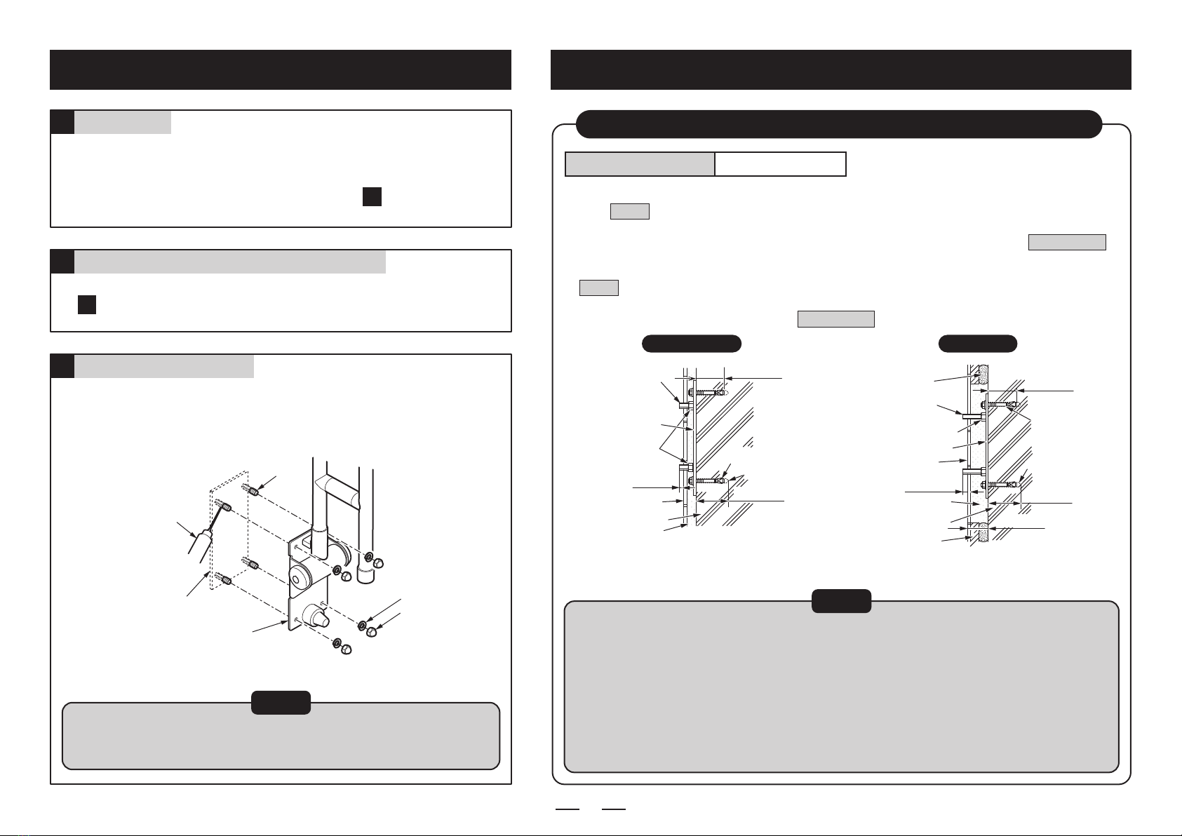
When the product is used in wet areas such
as a restroom, be sure to apply sealant
around the mounting holes.
If sealant is not applied, water may enter the back of the wall
and cause the product to come off or the wall to collapse,
which could result in user’s fall and injury.
Be sure to use TOTO-designated xing
brackets.
If TOTO-designated xing brackets are not used, the
handrail may come off or the wall may collapse, which could
result in user’s fall and injury.
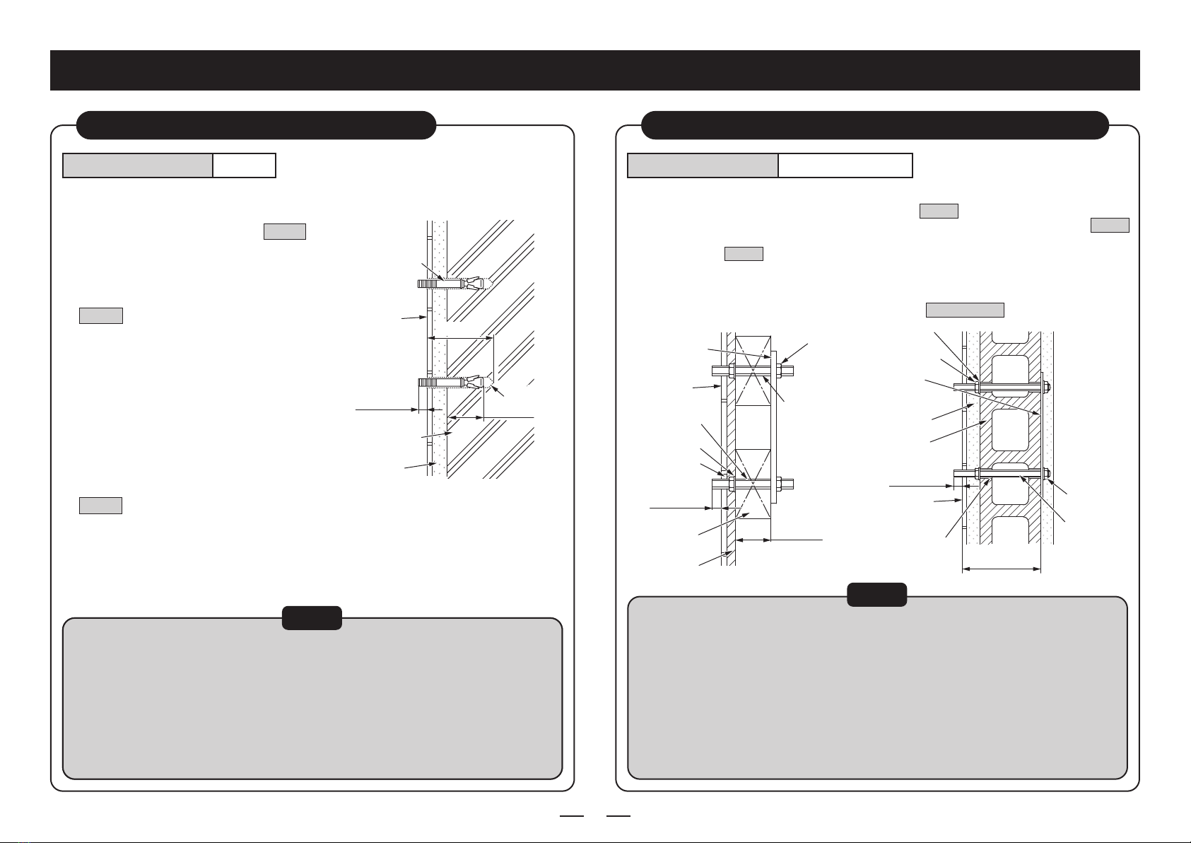
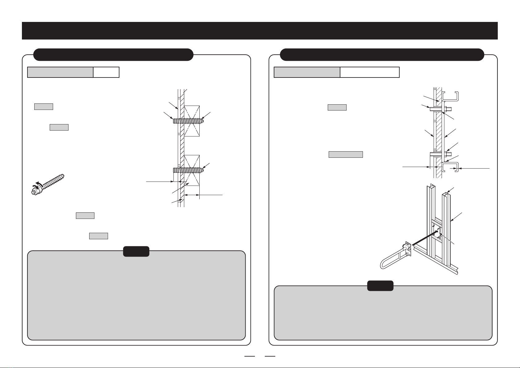
Make sure that the base has sufcient
thickness and is reinforced, and install the
handrail by the specied installation method.
If the base does not have sufcient thickness or is not
reinforced, and if you do not follow the specied installation
method for each base, the handrail may come off or the wall
may collapse, which could result in user’s fall and injury.
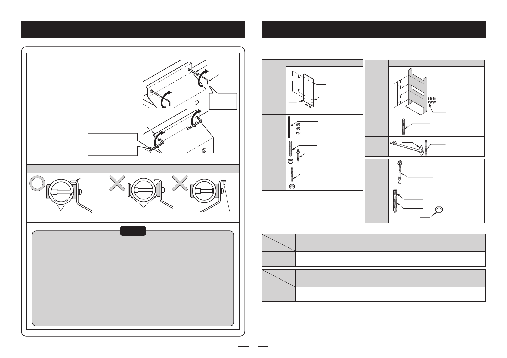
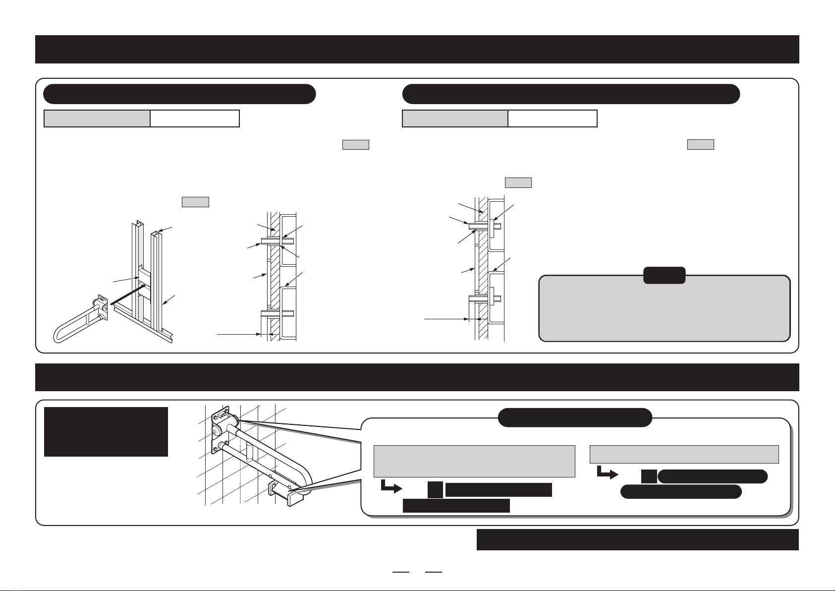
Make sure that the handrail has no backlash
after the installation is complete.
If the handrail has backlash, it may come off or the wall may
collapse, which could result in user’s fall and injury.
Anyone other than service engineers must not
disassemble, repair, or modify the product.
Failure to observe this warning could cause a user to fall due to the
damage or coming-off of the handrail and may result in injury.
Be sure to install this product on a strong wall
or building structure.
If the product is installed directly on a wall that is not strong enough,
including a soil wall and a gypsum board wall, it may come off or the
wall may collapse, which could result in user’s fall and injury.