TPL VISION Ring 80 Manual

Technical User gUide
inTrodUcTion
This User Guide contains warnings and guidance for correct and safe operation of the product. These instructions
must be followed at all times. TPL Vision will not be held responsible for problems caused by using the product
contrary to these instructions and the Warranty will be deemed invalid.
Unpacking
This product is packed at the factory using suitable materials for safe transport. To open the package, do not use
any cutting blade to avoid damaging the product(s). Please use the delivered accessories if needed. (Do not use
any other products or equivalents to replace the delivered accessories). In the event of damage occurring during
shipping, it must be reported to the carrier at time of delivery (including noting the damage in writing on thedeliv-
ery documents). It is also your responsibility to notify TPL Vision in writing of the damage within 24 hours of receipt
of the package. If these instructions are not followed, TPL Vision reserves the right not to accept requests for
return and exchange of damaged products.
risk class
The applicable Standard EN-62471 classies LED Lighting into 4 groups (or classes) according to their degree of
hazard severity. The table below summarises the risks associated with our various standard products.
Colour Class Risk
Red 625 nm, Cyan
505 nm, White WHI 0none
IR 860 nm 1low
TPL Vision can provide guidance notes to minimise
photo-biological risks, including the nominal mini-
mum operating distance. Please contact TPL Vision
through your usual representative for this information.
TPL Vision recommends the use of the protection
glasses that are listed in its catalog.
BEWARE: infrared light is invisible to the eye.
Please refer to LED Indicators on the product
to determine if it is operating.
Technical User gUide P2/12
Fixing
During the set up, the light has to beswitched off
and unplugged.
Please use the xing holes designed for thatpur-
pose. We recommend the using of M5 screws
(not supplied) with a tightening torque from 0.5
to 1.5 Nm.
We also recommend the use of a threadlocker
(not supplied) to avoid any risk of loosening.
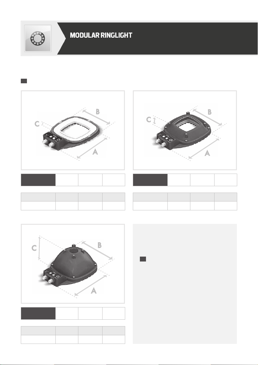
dimensions
DOME Length
(mm)
Width
(mm)
Height
(mm)
A B C
Dome 80 193 136 75
Dome 130 257 197 106.75
RING Length
(mm)
Width
(mm)
Height
(mm)
A B C
Ring 80 193 136 11*
Ring 130 257 197 11*
LOW ANGLE Length
(mm)
Width
(mm)
Height
(mm)
A B C
Low Angle 80 193 136 34.75
Low Angle 130 257 197 45.25
* with connectors: 31 mm.

P3/12
led indicaTors
Operating mode
Strobe
elecTrical connecTion
M12 – 5 MALE PINS M12 – 8 MALE PINS
nPOWER SUPPLY
nSTROBE
nDIMMING
nSECTOR CONTROL
nCOLOR CONTROL
nOVERDRIVE ENABLING
nLOCK KEYPAD
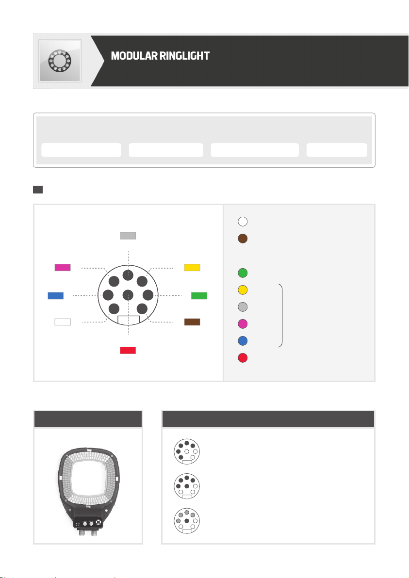
CONNECTION: M12 8 MALE PINS CONNECTOR
SECTOR CONTROL COLOR CONTROL OVERDRIVE ENABLING LOCK KEYPAD
Technical User gUide P4/12
REMOTE CONTROL PINOUT THROUGH PNP: 0-4V is OFF and 5-24V is ON.
ALL SECTORS +OVERDRIVE
ALL SECTORS CW +KEYBOARD DEACTIVATED
SECTOR CONTROL VIA M12 - 8 PINS
1
7
6
2
3
4
5
8
green
yellow
brown
blue
pink
white
red
grey
remoTe conTrol (connecTion)
1
24
3
1Active overdrive ➞ connect to 24VDC
2Change colours
➞ default colour: 1 (if not connected)
➞ colour 2 if connected to 24 VDC
3GND
4Sector 1
5Sector 2
6Sector 3
7Sector 4
8Deactivate keyboard and activate
the M12 8 pins connector
➞Connect to 24VDC
to turn ON
SECTORS MINIMUM WIRING

P5/12
M12 Connector 5 male pins
CONTINUOUS MODE :
2
4
1
+ 24 V
3GND
5DIM 0-10V
STROBE
NPN
STROBE
PNP
black
brown
blue
grey
white
+ 24 V
1
2
3
4
Ground
PNP
+ 24 V
NPN
1
2
3
4
Ground
or
5Dim 0-10V 5Dim 0-10V
+ 24 V
1
2
3
4
Ground
PNP
5Dim 0-10V
STROBE PNP
:
+ 24 V
NPN
1
2
3
4
Ground
STROBE NPN
:
5Dim 0-10V
EMC IMMUNITY CONNECTIONS: for greater
EMC immunity when using the light under Strobe
operation, congure the signal connections as
illustrated here. For Dimming, the Pin (5) should
be connected to avoltage between 0V and 10V to
ensure light output is correctly congured.
The M12 male connector 5 points is COM-
PLIANT with the M12 female connector 4 points.
In that case, thedimming option is not available.
sTrobe mode
PNP : from 5 to 24V for 100% ON. From 0 to 4V for 100% OFF.
NPN : less than 2V for 100% ON. Above 2.2V for 100% OFF. Max 24V.
sTrobe Triggering mode - pnp and npn
CONNECTION: M12 5 MALE PINS CONNECTOR
POWER SUPPLY STROBE DIMMING
+ 24 V
+ 24 V
1
2
3
4
Ground
PNP
5Dim 0-10V
STROBE PNP
:
+ 24 V
NPN
1
2
3
4
Ground
Ground
STROBE NPN
:
5Dim 0-10V

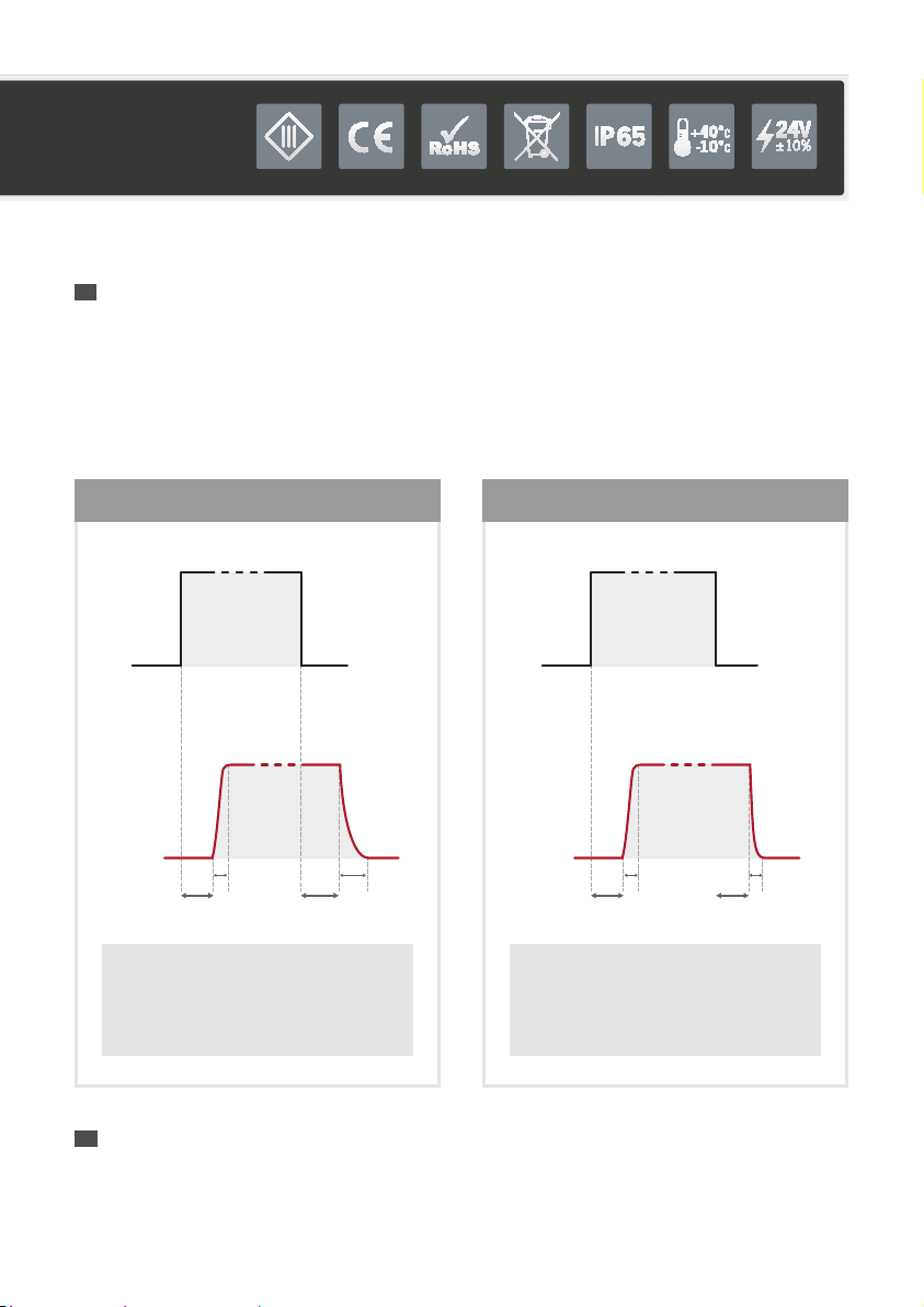
sTrobe Timing limiTs
• Standard version
Don’t exceed 310 Hz when strobing PNP/NPN in overdrive mode.
• Overdrive version
D max tmin t max max
frequency
100 % 5 µs CW 50 kHz
D max tmin t max max
frequency
10 % 5 µs 2 ms 310 Hz
[ D: duty cycle |t: pulse duration |CW: continuous working ]
Standard Mode
0 V
Active Overdrive
5 µs - CW
Overdrive Mode
24 V
Active Overdrive
2 ms max
10% duty cycle
Entrée Déclenchement
Sortie Éclairage
Triggering input
Light
10 µs 10 µs
Rise/Fall times in CW &
Overdrive Modes when under
PNP/NPN strobe control.
On time (t) & duty cycle (D)
in CW & Overdrive modes.
PNP/NPN
LED current
Courant Led
2 ms max
overdrive
Technical User gUide P6/12
sTrobing The lighT via pnp or npn behavioUr
P7/12
65 µs
80 µs
2 µs 25 µs
Change
Colours
LED
Current
65 µs
65 µs
10 µs 10 µs
Sector
Control
LED
Current
coloUrs secTors
Rising/falling times &
ON/OFF delays when changing colours
Rising/falling times &
ON/OFF delays when strobing sectors
with PNP at 24V
To control the LED Colour and illuminated Sector, the PNP or NPN trigger signal should be enabled in addition to
the Sector or Colour control signal(s). Timing diagrams below illustrate rise, fall and delay times.
If PNP and sectors are connected to 24V and if you strobe colours, there can be some delays between thetrigger
signal and the LED current.
If PNP is connected to 24V and you strobe sectors, there can be some delays between the trigger signal and
theLED current. In this conguration, you have protection for maximum 2ms.
sTrobing The lighT via coloUr & secTor inpUT behavioUr
If a trigger signal of more than 2ms is applied, the LED will only remain on for a maximum of 2ms.
Duty cycle protection: you can set a 10% duty cycle max.
If this is exceeded, internal protection circuitry will activate.
proTecTion in overdrive mode

Technical User gUide P8/12
power sUpply
Operational Voltage 24 V at the light input (±10%)
Absolute Maximum Voltage 30 V at the light input
Max. current consumption - strobe signal line 5 mA
Max. current consumption - remote control lines 5 mA
Max. current consumption - dimming control line 2 mA
dimming conTrol
20%
40%
60%
80%
100%
0 2 4 6 8 10
VOLTS
Dimming between 0 & 10 V.
With 0V applied to the Dimming pin,
theproduct is at 100% of its lighting
power. With 10V applied, it is reduced
to30% oflighting power.
secTor conFigUraTions
1
24 3
1
24
3
1
24
3
1
24
3
A B C

P9/12
The Modular Ringlight works in manual control and
continuous working (CW) mode by default. To use
theremote control, youneed to connect the 8 pin cable
and apply PNP signals to the relevant pins. TheModular
Ringlight has Teach and Run mode.
keypad conTrol
Colour and Sector Selection
• Program settings: push the 2 buttons together
for 3 - 4 seconds,
• Change settings: 1 push of Colour and / or
Sector button(s) until desired configuration
is selected,
• Save settings: push the 2 buttons together
for3 - 4 seconds.
User saFeTy
Do not modify or dismantle all or part of the product.
Respect the power supply voltages and the connection terminals.
Ensure power supply is switched off whilst connecting product and turn on only once product
isfully connected. Failure to do this may damage the product and invalidate theWarranty
Do not stare at the lighting source directly.
Follow advice below for installation to minimise operator exposure to the light source.
INSTALLATION GUIDANCE:
• Forbid or limit the direct access to the lighting source (exposure into the radiation axis).
• Establish a security perimeter to prevent the operators from approaching the lighting source beyond therecom-
mendations of the manufacturer.
• If the workstation permits it, introduce a lter that will stop the lighting radiation under a xed or adjustable
frame between the source and the operator. When these measures cannot be implemented, supply theoper-
ators with glasses (class 4) available from TPL Vision, or with a dedicated protective mask, that will stop
thelighting radiation.
It is the responsibility of the persons installing this product to ensure that all means possible (such as those stated
above) have been implemented to reduce exposure of the machine operators to the light emitted from this product.
Colour selection
Sector
selection

Technical User gUide P10/12
eqUipmenT mainTenance
warranTy inFormaTion
CLEANING (when the product is switched off)
Please use a soft and dry cloth. Do not use any abrasive material. Do not use any cleaning solvent or aggressive
chemical product. TPL Vision recommends to use isopropyl alcohol.
Further information on the applicable Warranty can be found on the TPL Vision website:
https://www.tpl-vision.com/warranty/
operaTing condiTions
-10° to +40°C / 80% of humidity without condensation. Not for outdoor use.
No thermal shock (maximum temperature variation: 10°C in 24h).
binning inFormaTion
advised bandpass FilTers
TPL Vision is extremely careful about BIN sorting in the selection ofLEDs for their products.
Specifically for the Cyan series on this product, the human eye is very sensitive to colour variations. Itmay appear
to the customer that they do not appear the same between two cyan LED products. Despite any noticeable
differences, the peak wavelength variation does not exceed 10nm.
Here are thefollowing bandpass camera filters we recommend to fit with the Modular Ringlight:
• White LEDs: no filter • Red LEDs: BP 635
• Infrared LEDs: LP 830 • Cyan LEDs: BP 505
Further information on the TPL Vision website.

P11/12
associaTed accessories
M12 8 pins
Remote control
3 m Ref: C-M12-8P-3M
5 m Ref: C-M12-8P-5M
10 m Ref: C-M12-8P-10M
M12 5 pins
Power supply
2 m Ref: C-M12-5P-2M
5 m Ref: C-M12-5P-5M
10 m Ref: C-M12-5P-10M
Mounting
80mm & 130mm
Ref: TPL-MOUNT-MR

www.tpl-vision.com
TPL VISION
IS AN ISO9001
CERTIFIED MANUFACTURER
+44 (0)1738 310 392 contact@tpl-vision.co.uk
Brenchley House, School Road
Charing, Kent TN27 0JW
United Kingdom
Features and presentations liable to changes without notice. Ref.UG-030301-B1, 2020/11 edition.
This manual suits for next models
5
Table of contents
Other TPL VISION Lighting Equipment manuals

TPL VISION
TPL VISION SDOME II 130 User manual

TPL VISION
TPL VISION M-EBAR User manual

TPL VISION
TPL VISION LITE LBAR+ Series User manual

TPL VISION
TPL VISION SQUARE LIGHT RGB User manual

TPL VISION
TPL VISION Modular Ringlight Operation and maintenance manual

TPL VISION
TPL VISION BLBAR+ User manual

TPL VISION
TPL VISION TRING User manual

TPL VISION
TPL VISION THINLED 1 User manual

TPL VISION
TPL VISION MEDIUM MBACK User manual


