Tramont TRS Series User manual
Serial # _________________________________________
UL Listed # __________________________________________
Order # __________________________________________
a UCA Group Company
Installation &
Operation Manual
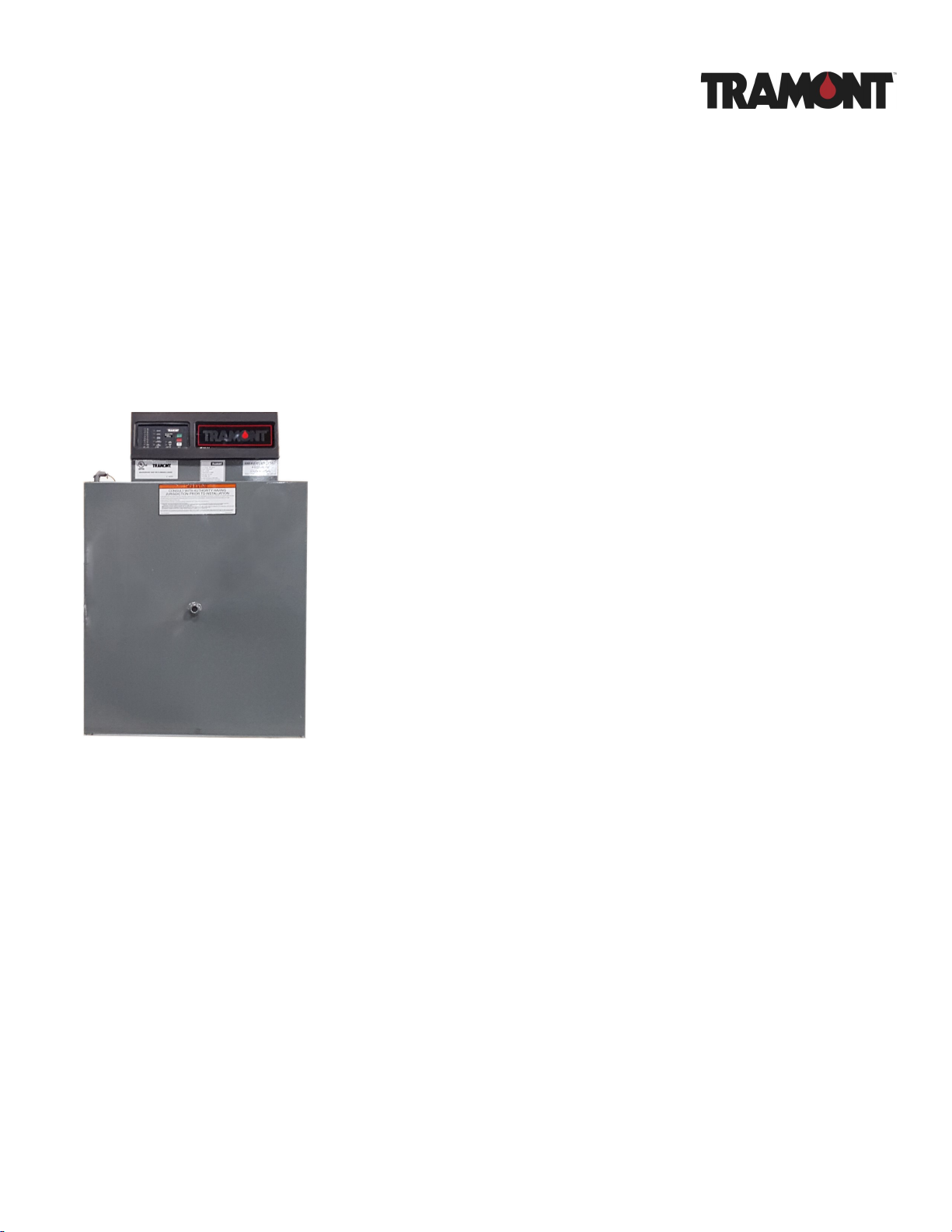
Day Tank
TRS Series

Tramont Manufacturing TRS Series Day Tank
Installation and Operation
Table of Contents
Warnings..................................................................................................................1
TRS Series Day Tanks ............................................................................................2
System 2000PLUS™ ECM ......................................................................................3
Installation Diagram: Main Tank Above Day Tank ..................................................4
Installation Diagram: Main Tank Below Day Tank ...................................................5
Installation Diagram: Main Tank Below Day Tank, Piping Above Day Tank ...........6
TRS Series Start-up and Test Procedures ..............................................................7
Tramont Standard Day Tank Diagrams .................................................................12
Tramont Day Tank Specifications ..........................................................................13
System 2000PLUS ECM Specifications ................................................................14
Standard Pump and Motor Specifications .............................................................17
Design Considerations of a Day Tank Fuel Transfer system ................................18
Mechanical and Plumbing Guide ...........................................................................21
Sequence of Operation - TRS Day Tank ...............................................................23
Trouble-shooting Tips: ECM Functional Light Flashing ........................................24
System 2000PLUS Problem Report ......................................................................25
Common Day Tank Parts.......................................................................................26
Tramont Manufacturing LLC Product Warranty .....................................................27
Tramont Manufacturing LLC
3637 N. Holton St.
Milwaukee, Wisconsin, USA 53212
Phone: 414-967-8800 Fax: 414-967-8811 sales@tramont.com www.tramont.com

TRS Series Day Tank
Tramont Manufacturing 3637 N. Holton St. Milwaukee, WI 53212
Phone: 414-967-8800 Fax: 414-967-8811 sales@tramont.com www.tramont.com
© Tramont Manufacturing June 2017
1.
WARNINGS
This Day Tank has been pressure tested to 5 psi for weld integrity. However, IT IS NOT DESIGNED
TO BE A PRESSURE VESSEL.
This tank is designed, manufactured and intended for DIESEL FUEL ONLY.
This tank is intended for STATIONARY INSTALLATIONS ONLY.
Installation of solenoid valves, check valves, or other devices may be required to ensure tank does
not overflow due to fuel draining from pipes that are situated higher than the Day Tank.
The overflow fitting of this atmospheric Day Tank must be plumbed without downsizing in a
CONTINUOUS DOWNWARD PATH to the main tank. If you are unable to plumb in a continuous
downward path, A REVERSE PUMP IS REQUIRED. Consult factory for more information.
If a continuous downward path is impossible, consult the installation guide or factory for overflow
safety requirements. (Installation for Main Tank Above Day Tank).
OPTIONAL EPOXY LINING
To prevent fuel contamination and deterioration of the epoxy lining, this tank must be allowed
to properly cure. The curing time is seven (7) days from the time of application.
This tank lining was applied on ____________________________________
TRS Series Day Tank
Tramont Manufacturing ⚫ 3637 N. Holton St. Milwaukee, WI 53212
Phone: 414-967-8800 ⚫ Fax: 414-967-8811 ⚫ sales@tramont.com ⚫ www.tramont.com
© Tramont Manufacturing Janauary 2020
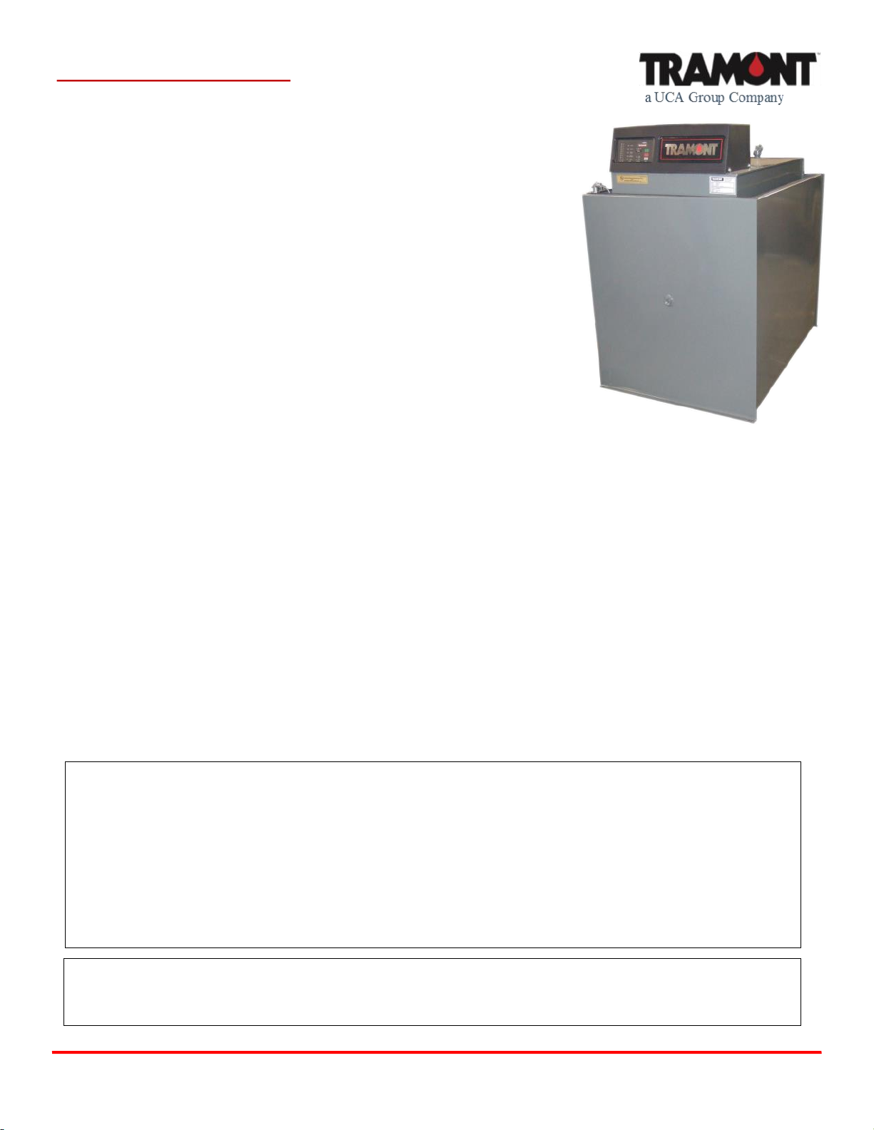
TRS Series Day Tanks: Quality,
reliability and advanced technology
The Tramont TRS Series is the industry standard in Day
Tank systems. In addition to the precision engineering and
quality construction that go into all of our systems, the TRS
Series features the exclusive Tramont System
2000PLUS™ Electronic Control Module (ECM).
Standard Features
TRS Series day tanks include the following standard
features:
• 1/3 HP, 1 phase, 115 VAC, 60 Hz thermally protected
motor.
• 2 GPM, high lift gear pump with 3/8" NPT inlet and
discharge.
• System 2000PLUS Electronic Control Module (see
facing page for description).
• Heavy gauge steel construction.
• Gray painted exterior, rust-inhibitor coated interior.
• Removable, nonconductive cover.
• Tank 1" NPT fittings are engine supply, engine return,
overflow and alternate engine return. Other fittings
include 2" NPT for normal vent, NPT sized as
appropriate for emergency vent, and one 3/8" NPT
basin drain for tanks through 275 gallons, 1" NPT for
larger tanks. (If tank includes containment basin,
alternate engine fitting omitted and drain provided on
basin only).
• Square 4-1/2" inspection port located below electrical
controls.
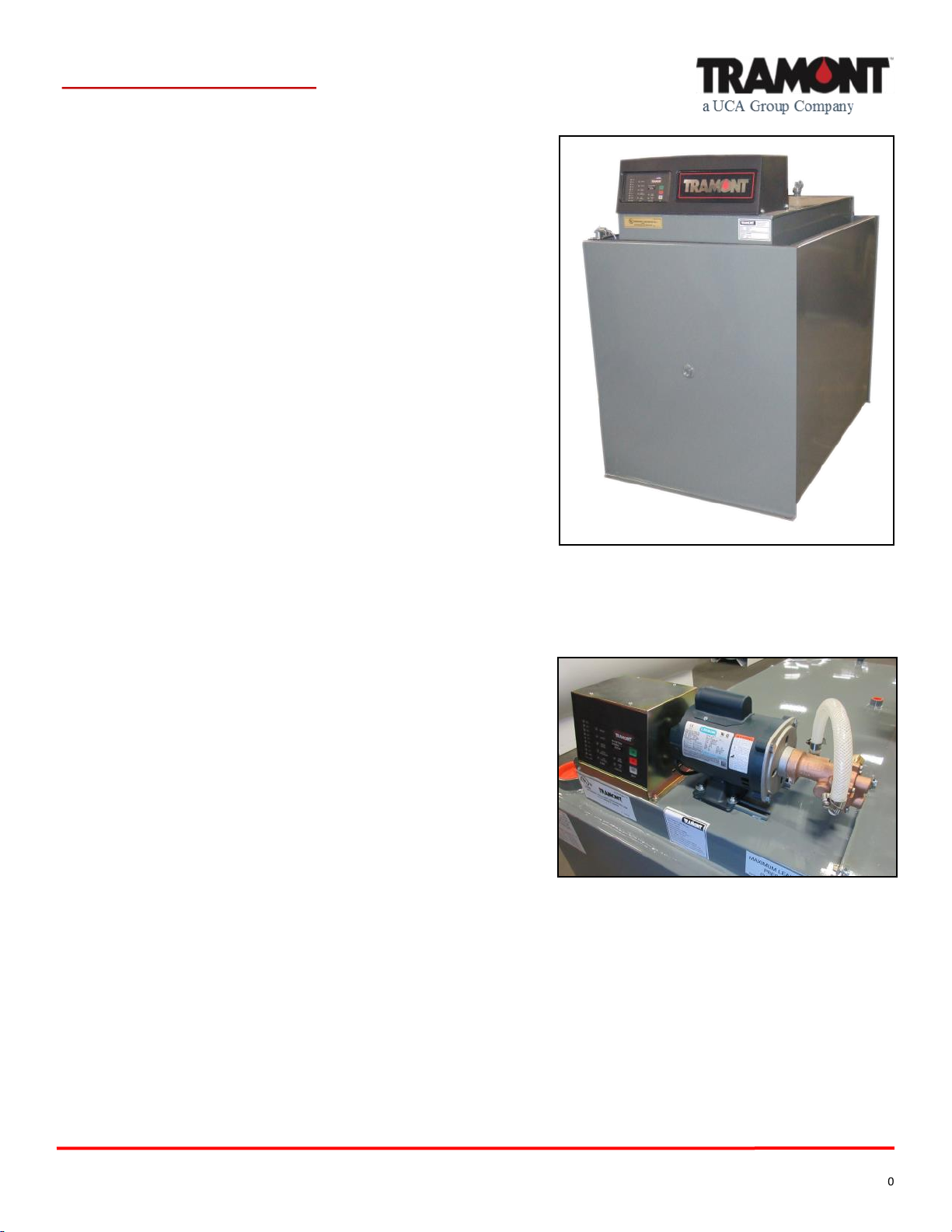
TRS Series Day Tanks include the System
2000PLUS ECM, 1/3 HP motor and 2 GPM
pump as standard. A full line of optional
features, like the 1/2 HP motor pictured here,
are also available.
Tramont TRS-Series Day Tank with optional
open-top rupture basin and fuel-in-basin alarm.
2.

© Tramont Manufacturing January 2020
Tramont Manufacturing ⚫ 3637 N. Holton St. Milwaukee, WI 53212
Phone: 414-967-8800 ⚫ Fax: 414-967-8811 ⚫ sales@tramont.com ⚫ www.tramont.com
TRS Series Day Tank
The System 2000PLUS ECM:
The leading performer in Day
Tank monitoring and control
The System 2000PLUS™ Electronic Control Module
(ECM) gives you state-of-the-art control of your Day
Tank system. The System 2000PLUS is standardly
included on all Tramont TRS Series day tanks. This UL
Listed, microprocessor-based ECM represents a
significant advance in fuel system control. Old-style
controllers utilize individual, electro-mechanical float
switches for each monitoring function. A malfunction
can go undetected for months or years until there is a
crisis. The System 2000PLUS is self-diagnostic, and
features a single sensor for main monitoring functions.
It lets you know immediately if there is a problem. You
have time to react, avoiding a costly disruption. The
System 2000PLUS gives you fast, accurate,
comprehensive monitoring, and is available exclusively
from Tramont.
Standard Features
The System 2000PLUS ECM offers the following
standard features:
• UL 508 Listed.
• Operates on standard 120 VAC, 1 phase system,
50/60 Hz.
• LED indicators for all functions.
• Fuel level sensor.
• Motor control relay with LED signal, rated up to 1/2
HP.
• High and low fuel level warnings.
• Critical low fuel level warning for engine shutoff.
• Fuel-in-rupture-basin warning interface.
• ECM functional signal.
• Manual control with On, Off and Test buttons.
• Secure internal test button for testing warning LEDs
and remote annunciation of warnings.
3.
ECM Single Supply Pump.
ECM Duplex Supply Pumps.
ECM Rear.
Tramont Manufacturing LLC
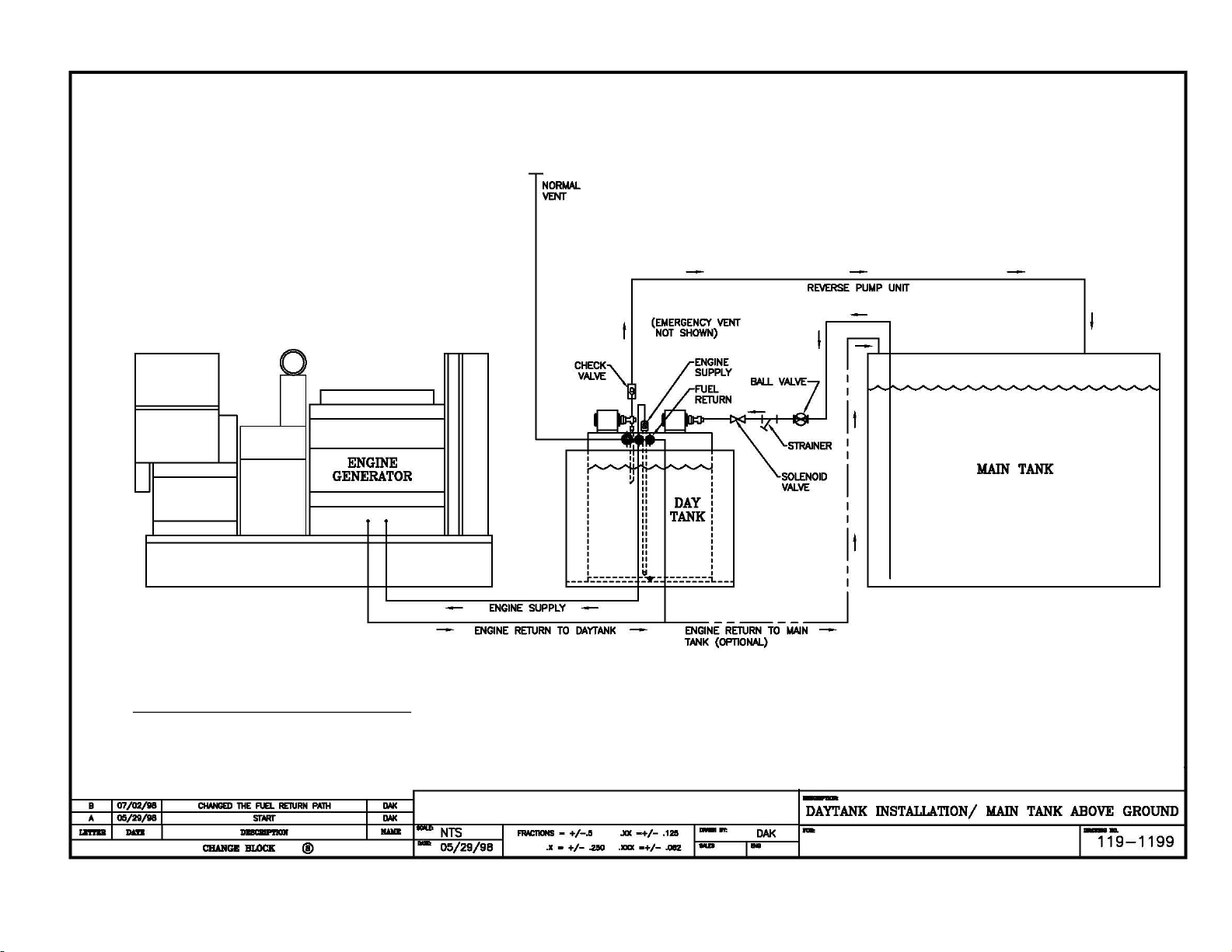
IMPORTANT: This diagram is depiction of a typical installation
and is intended for general reference purposes only. Consult with
site architect or design engineer for specific piping and other
installation requirements. Consult with generator manufacturer to
determine engine return capabilities.
© Tramont Manufacturing 2017
Day Tank Installation: Main Tank Above Day Tank
Supply and Return Pumps
4.
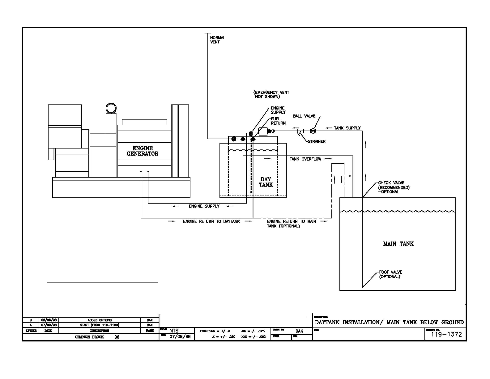
Tramont Manufacturing LLC
Day Tank Installation:
Main Tank Below Day Tank
Supply Pump with Gravity
Overflow Return
5.
IMPORTANT: This diagram is depiction of a typical installation
and is intended for general reference purposes only. Consult with
site architect or design engineer for specific piping and other
installation requirements. Consult with generator manufacturer to
determine engine return capabilities.
© Tramont Manufacturing 2017

Tramont Manufacturing LLC
Day Tank Installation:
Main Tank Below Day Tank,
Piping Above Day Tank
Remote Supply Pump with Day Tank
Mounted Return Pump
6.
Depending upon
distance and li, it may
be possible to locate
pump on the Day Tank.
The pump li and head
worksheets on page 20
can be used to help
esmate requirements.
IMPORTANT: This diagram is depiction of a typical installation
and is intended for general reference purposes only. Consult with
site architect or design engineer for specific piping and other
installation requirements. Consult with generator manufacturer to
determine engine return capabilities.
© Tramont Manufacturing 2017
TRS Series Start-Up and Test Procedures
Follow these steps when installing your Tramont Manufacturing
TRS-Series day tank to ensure proper operation of the system.
PRIOR TO INITIATING START-UP AND TEST PROCEDURES,
VERIFY THE FOLLOWING:
• Consult with authorities having jurisdiction to determine local installation
and operation requirements.
• Plumbing and electrical work must be performed by qualified service
personnel.
• Install any shipped loose tank accessories.
• Check all pipe connections and fittings on the tank and tighten as necessary
to avoid leakage.
• Normal and emergency vents are recommended to be extended above the
top of the main tank.
• If the main tank is located below the day tank, the day tank overflow line shall
be continuous piping, without valves or traps, back to the source tank or to
a collection system.
• If it is not possible to pipe the overflow line unimpeded in a continuous downward path, then a reverse pump is
necessary to return fuel to the source tank or collection system.
• If the main tank is located above the day tank, a strainer and solenoid valve must be installed to prevent fuel from
siphoning from the main tank. The strainer must be placed before the solenoid to help prevent debris from clogging
the valve:
If the supply pump is mounted on the day tank, install the strainer and solenoid valve at the supply pump inlet.
If the supply pump is not mounted on the day tank, install the strainer and solenoid as close as possible to the
day tank inlet. If the solenoid is too far from the inlet it may cause a high fuel level alarm when fuel drains back
into the tank.
• The day tank must be positioned so that the highest fuel level in the tank is lower than the fuel injectors on the
generator. (Verify injector height with generator manufacturer).
• TRS Series tanks include the following standard fuel level settings. Levels may vary on tanks with custom settings.
Single Supply Pump Duplex Supply Pumps
PUMP ON: 87% 1ST PUMP (A OR B) ON: 87% 2ND PUMP (A OR B) ON: 75%
PUMP OFF: 100% 1ST PUMP (A OR B) OFF: 100% 2ND PUMP (A OR B) OFF: 100%
NOTE: Sequence of pump operation (A or B) depends upon lead-lag cycle.
Single and Duplex Pumps
HIGH FUEL LEVEL: 106% CRITICAL LOW FUEL LEVEL: 6%
LOW FUEL LEVEL: 62% CRITICAL HIGH FUEL LEVEL: 112%
Note: CRITICAL HIGH FUEL LEVEL is an optional feature that uses the same indicator light as the HIGH
FUEL LEVEL.
IMPORTANT!
If system start-up and test results deviate from the description on the following pages, consult the troubleshooting
guide included with the tank, or contact Tramont Sales and Service.
TRS Series Day Tank
Tramont Manufacturing 3637 N. Holton St. Milwaukee, WI 53212
Phone: 414-967-8800 Fax: 414-967-8811 sales@tramont.com www.tramont.com
7.
PAGE 1 OF 5
Tramont TRS-Series
Day Tank.
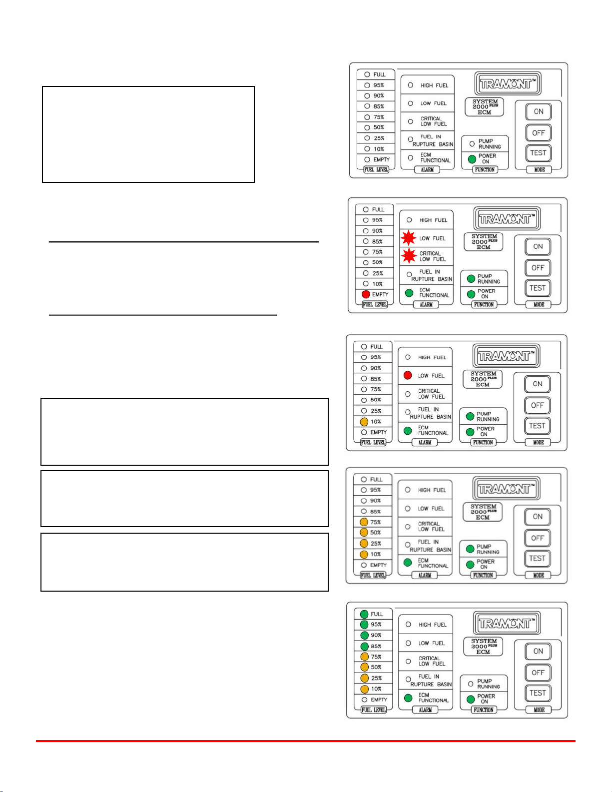
FILLING THE TANK
IMPORTANT!
If power to the System 2000PLUS Electronic
Control Module (ECM) is interrupted at any
time the pumps will activate and the tank will
fill to 100% capacity when power is restored.
This includes the first time you energize
the ECM.
1. Make sure motor starters are connected (if applicable).
2. Energize the ECM. This will activate the pump.
• IF YOU DO NOT WANT TO FILL THE TANK AT THIS TIME:
Immediately press the OFF button. This will deactivate the
pump. The POWER ON button will remain illuminated.
(FIGURE 1) When you are ready to fill the tank press the ON
button and follow the steps below.
• IF YOU WANT TO FILL THE TANK AT THIS TIME:
Do not press the OFF button after energizing the ECM. The
POWER ON indicator light will be illuminated, the pump will
activate and the tank will begin to fill. As the tank fills, the
PUMP RUNNING, ECM FUNCTIONAL, LOW FUEL
(flashing), CRITICAL LOW FUEL (flashing) and EMPTY
indicator lights will be illuminated. (FIGURE 2)
IMPORTANT!
If the tank duplex supply pumps, both will activate. The PUMP
A RUNNING and PUMP B RUNNING lights will be
illuminated until the tank is completely filled. See page 3 for
duplex ECM illustrations.
IMPORTANT!
Verify that the fuel line and pump quickly achieve prime and
fuel is flowing freely into the tank. “Running dry” will cause
permanent damage to the pump and motor.
IMPORTANT!
If fuel leakage is detected, immediately stop filling the tank.
Make sure tank is plumbed correctly and tighten fittings as
necessary before restarting fill.
3. As the tank continues to fill, the CRITICAL LOW FUEL light
will go off, and then the 10% FUEL LEVEL indicator light will
become illuminated. (FIGURE 3)
4. As the tank continues to fill, the 25%, 50% and 75% FUEL
LEVEL lights will be illuminated. The LOW FUEL light will go off
once the tank exceeds 62% capacity. (FIGURE 4)
5. When the tank is completely filled all FUEL LEVEL lights
will be illuminated. The PUMP RUNNING light will go off.
(FIGURE 5)
Tramont Manufacturing 3637 N. Holton St. Milwaukee, WI 53212
Phone: 414-967-8800 Fax: 414-967-8811 sales@tramont.com www.tramont.com
TRS Series Start-Up and Test Procedures, continued...
FIGURE 1 - 5:
ECM single
supply pump
sequence of
operation
during tank fill.
FIGURE 1
FIGURE 3
FIGURE 2
FIGURE 4
FIGURE 5 PAGE 2 OF 5
8.
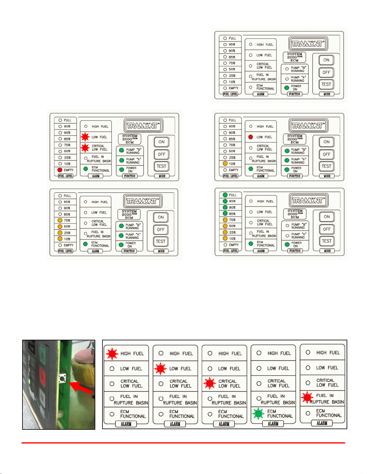
TESTING THE ECM
The following procedure verifies that the relays for each fuel level condition are functioning properly.
1. Remove the cover from the ECM.
2. Press the test button on the inside of the front panel on the ECM and hold it down. (FIGURE 6)
If the unit is operating properly the ALARM indicator lights will flash one-by-one in this sequence: HIGH FUEL, LOW FUEL,
CRITICAL LOW FUEL, ECM FUNCTIONAL, and FUEL IN RUPTURE BASIN. (FIGURE 7)
3. If the test cycle completes successfully, release the test button and replace the cover on the ECM.
FIGURE 6
FIGURE 2 FIGURE 3
FIGURE 4 FIGURE 5
FIGURE 1
FIGURE 7
Tramont Manufacturing 3637 N. Holton St. Milwaukee, WI 53212
Phone: 414-967-8800 Fax: 414-967-8811 sales@tramont.com www.tramont.com
Figure 1: ECM energized; unit in OFF mode.
Figure 2: Pumps activated, tank begins to fill.
Figure 3: 10% FUEL LEVEL light on, CRITICAL LOW FUEL light off.
Figure 4: LOW FUEL LEVEL light off when tank exceeds 62%
capacity.
Figure 5: Tank is full, pumps deactivate.
TRS Series Start-Up and Test Procedures, continued…
ECM duplex supply pump sequence of operation
during tank fill
PAGE 3 OF 5
9.
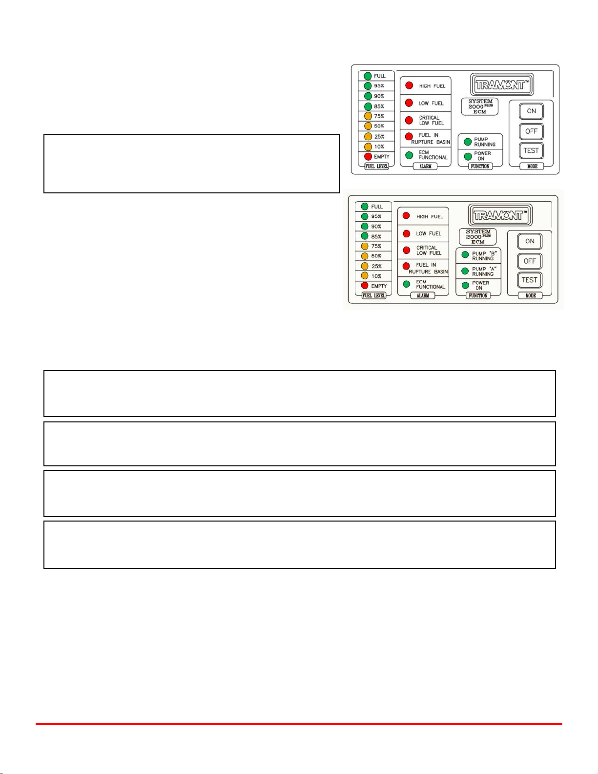
TRS Series Start-Up and Test Procedures, continued...
TESTING THE OVERFILL LINE
For tanks with a gravity fed return line
The purpose of this test is to verify that the overfill line is plumbed in
a continuous downward path with no obstructions so that excess fuel
flows unimpeded back to the main tank.
IMPORTANT!
Carefully monitor the fuel level while performing these steps. If the
overfill line is not plumbed correctly and fuel continues to enter the
day tank a fuel spill may occur.
1. Press and hold the TEST button on the front of the ECM. All
indicator lights will be illuminated, and the pump will activate.
(FIGURE 1) If the tank is equipped with duplex pumps both will run.
(FIGURE 2)
2. Monitor the fuel level in the tank. Make sure as fuel rises to the
level of the overfill fitting that:
• The fuel level goes no higher than the overflow fitting.
• The excess fuel flows unimpeded back to the main tank.
3. Release the TEST button.
For tanks with a reverse pump
The purpose of this test is to verify the proper operation of the reverse pump when the tank exceeds a high fuel level.
IMPORTANT!
If the reverse pump does not activate and deactivate as described below consult your electrician or contact Tramont
Sales and Service.
IMPORTANT!
The reverse pump operates independently of the supply pump. It is activated by a separate, normally closed, critical
high float switch.
IMPORTANT!
Carefully monitor the fuel level while performing the following test. If the reverse pump does not activate the tank
will continue to fill, and a fuel spill may occur.
IMPORTANT!
Verify that the overflow line includes no valves or traps and that the fuel flows unimpeded back to the main tank. If
the flow is obstructed a fuel spill may occur.
1. Press and hold the TEST button on the front of the ECM. All indicator lights will be illuminated, and the supply
pump will activate. (FIGURE 1) If the tank is equipped with duplex pumps both will run. (FIGURE 2)
2. When the tank reaches 112% of normal full capacity the reverse pump will activate. The reverse pump will shut off
within a few seconds as the fuel drops below the 112% level.
3. Release the TEST button. The tank will still be in a high fuel level state (just under 112% capacity).
FIGURE 1
FIGURE 2
PAGE 4 OF 5
Tramont Manufacturing 3637 N. Holton St. Milwaukee, WI 53212
Phone: 414-967-8800 Fax: 414-967-8811 sales@tramont.com www.tramont.com
10.
TRS Series Start-Up and Test Procedures, continued...
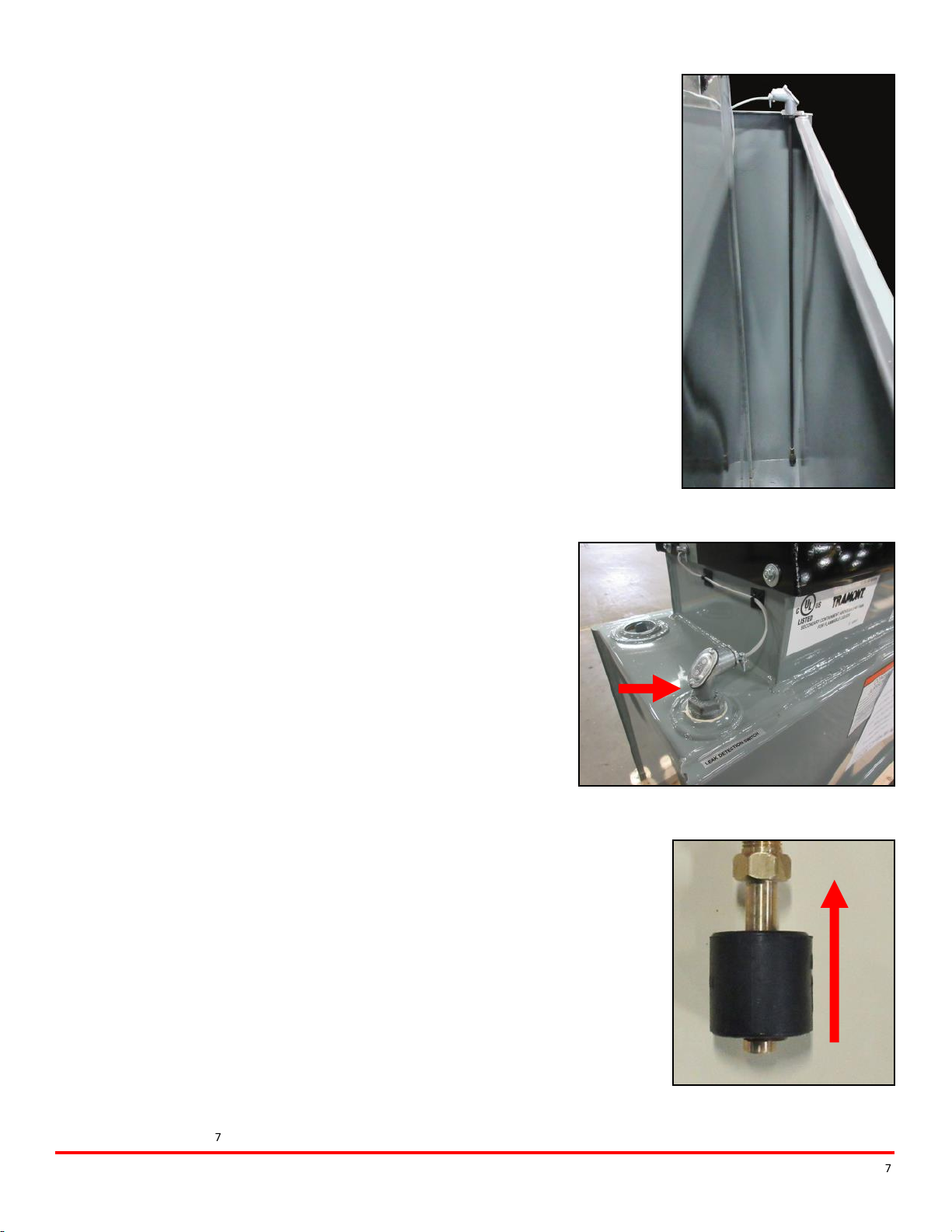
TESTING THE FUEL-IN-BASIN SWITCH
The fuel-in-basin switch, also referred to as a “leak detection switch,” is designed
to detect the presence of fuel in the containment basin. The switch is installed and
connected to the ECM. Follow the steps below if you would like to test the switch
to verify it has not been damaged in shipping and is working properly.
For tanks with an open top basin
The switch is readily accessible on a tank with an open top basin. (FIGURE 1)
1. Press the ON button on the ECM face.
2. Using a long, narrow, rigid implement (for example, a metal rod), reach into the
basin and carefully raise the float at the end of the switch assembly. (FIGURE 3)
If the switch is operating properly, the FUEL IN RUPTURE BASIN indicator light
on the ECM face will activate within a few seconds.
3. Lower the float. If the switch is operating properly, the FUEL IN RUPTURE
BASIN indicator light will go out within a few seconds.
For tanks with a closed top basin
On a closed top basin the switch is concealed within the containment area and must
be removed for testing. (FIGURE 2)
1. Remove the cover from the ECM.
2. Disconnect the fuel-in-basin switch wires from the inside of the ECM.
3. Depending upon how the tank is configured, you may have to
pull the wires through conduit so that the switch can be removed
from the basin. Once the wires are free, carefully unscrew the fuel-in-
basin switch and lift it out of the tank.
4. Reconnect the switch to the ECM.
5. Depress the ON button on the ECM face.
6. Raise the float switch. (FIGURE 3) If the switch is operating
properly, the FUEL IN RUPTURE BASIN indicator light on the ECM
face will activate within a few seconds.
7. Lower the float. If the switch is operating properly, the FUEL IN
RUPTURE BASIN indicator light will go out within a few seconds.
8. Press the OFF button on the ECM.
9. Re-insert the switch into the basin fitting and screw it into place.
10. Run the wires back through conduit as necessary and reconnect
them to the ECM.
11. Replace the cover on the ECM. Press the ON button to reactivate
the ECM.
PAGE 5 OF 5
June 2017
Tramont Manufacturing 3637 N. Holton St. Milwaukee, WI 53212
Phone: 414-967-8800 Fax: 414-967-8811 sales@tramont.com www.tramont.com
FIGURE 1
FIGURE 2
FIGURE 3
11.
© Tramont Manufacturing 2017

Day Tank
Tramont Manufacturing 3637 N. Holton St.. Milwaukee, WI 53212
Phone: 414-967-8800 Fax: 414-967-8811 sales@tramont.com www.tramont.com
© Tramont Manufacturing June 2017
12.
Drain is 1” NPT on tanks 300 gallons and above.
On tanks with basin:
• Drain is on basin only
• Alternate engine fitting is eliminated
• Engine supply fitting is moved to top of tank
with 2” vent, overflow and fuel return fitting.
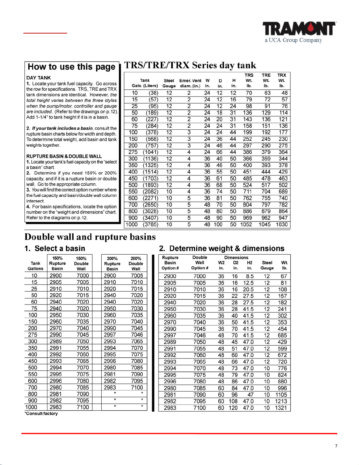
Tramont Standard Day Tank Diagrams
IMPORTANT: These diagrams depict standard Tramont Manufacturing Day Tanks.
The appearance and configuration of a Day Tank may vary due to special customer requests.
2” NPT VENT
Day Tank
Tramont Manufacturing 3637 N. Holton St. Milwaukee, WI 53212
Phone: 414-967-8800 Fax: 414-967-8811 sales@tramont.com www.tramont.com
© Tramont Manufacturing June 2017
13.
Tramont Day Tank System Specifications

TRS Series Day Tank
Tramont Manufacturing 3637 N. Holton St. Milwaukee, WI 53212
Phone: 414-967-8800 Fax: 414-967-8811 sales@tramont.com www.tramont.com
© Tramont Manufacturing June 2017
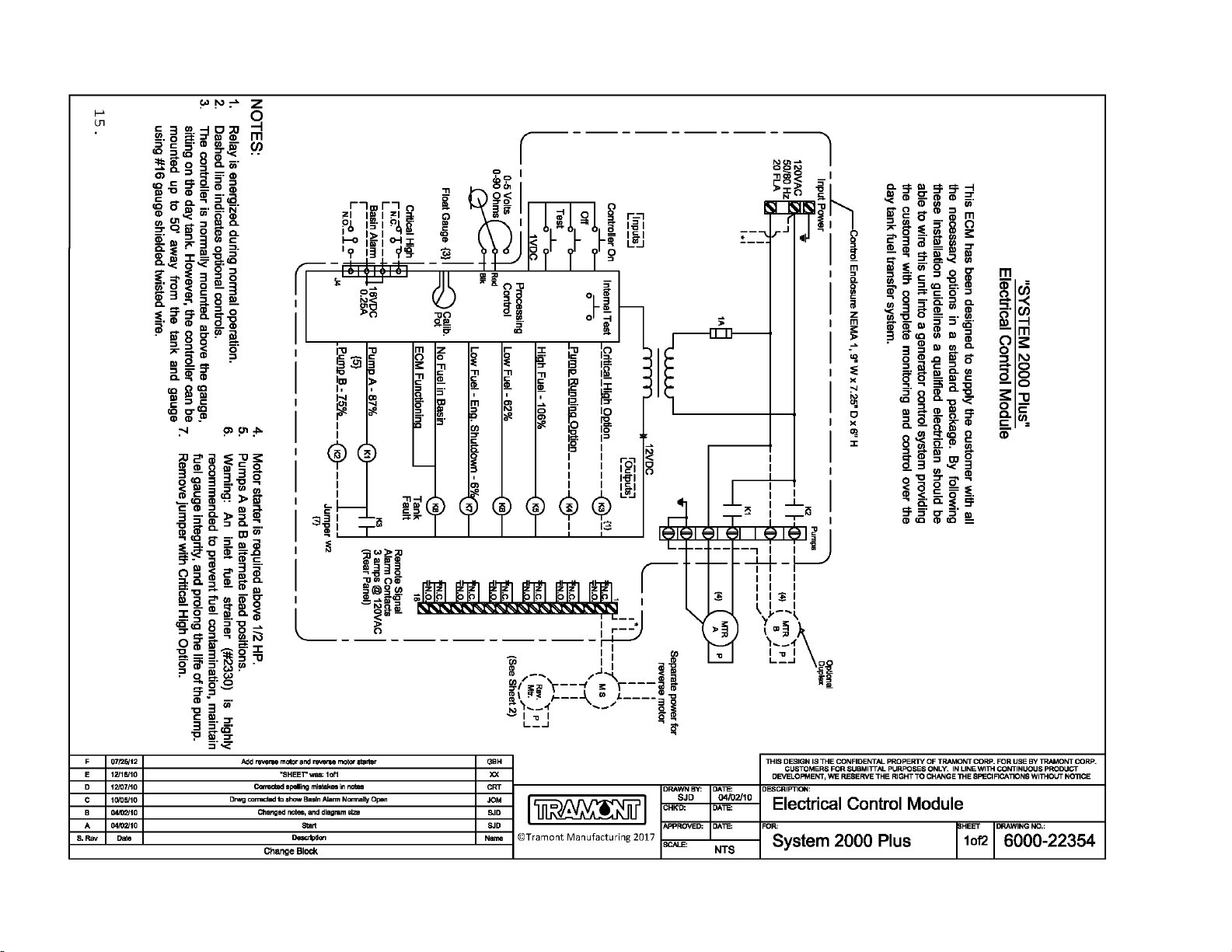
Day Tank Control Specification:
System 2000PLUS™ ECM
GENERAL
This section covers the electrical description and installation of the Tramont standard System 2000PLUS™ electronic control module (ECM).
Installation of the ECM should be performed by a qualified electrician. These specifications provide information on standard System
2000PLUS features.
DESCRIPTION
The heart of the “SYSTEM 2000” ECM is an electrical analog float gauge providing signals to the ECM for:
Fuel level indication Pump control High fuel level warning
Low fuel level warning Low fuel level shut off ECM functional signal
All signals and warnings are provided with N.O. and N.C. contacts for remote annunciation. The ECM can be manually controlled by ON,
OFF, and TEST push buttons. In addition, an internal test button allows for a periodic test of all warning LEDs and remote annunciation relays.
FUNCTIONS
The purpose of the ECM is to maintain the fuel level of the Day Tank by controlling a pump/motor. The pump is off at the normal fuel level and
is activated at 87% full. A “pump running” indicator LED is on when the pump is activated. Motor relay is prewired to pump motor.
WARNING: When ECM “OFF” push button is engaged the unit is disabled, however, 120 VAC power is still present within the ECM, indicated
by the “power on” LED.
OPTIONS
1920 Duplex pumping system. Adds 2nd pump and motor for safety redundancy. Control alternates lead pump.
1930 Controls are available for 12 VDC operation. Single or duplex. Consult factory for specifications.
3240 Pump running contacts for remote annunciation.
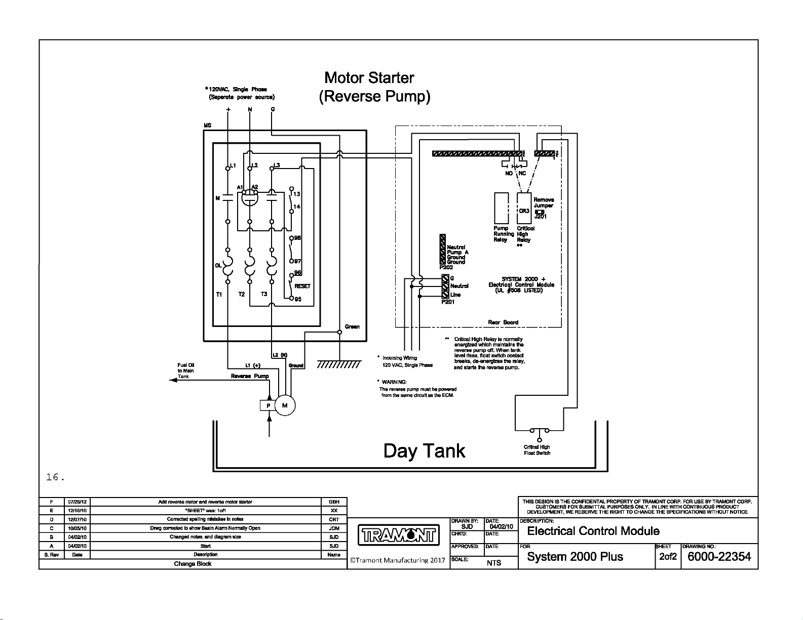
3250 Critical high shutdown. Separate float switch senses critical high fuel level, disengaging motor and optional solenoid valve. Warning
relay supplied for remote annunciation.
INCOMING POWER
The ECM is powered by a customer-supplied 120 VAC line. Power terminals are accessible by removing four cover screws on the ECM and
removing the ECM cover exposing the terminal strip. Wires should be run through knockout provided.
LEVEL SENSOR
The day tank’s level is determined by an electrical analog float sender located below the ECM on the inspection plate cover. The sensor
provides a 0 – 90-ohm signal to the ECM, which converts it to a precise fuel level. Fuel level is indicated by nine incremental LEDs on the
ECM from EMPTY to FULL.
ALARMS
The ECM has five standard alarm conditions. Each alarm is indicated locally by an LED and remotely by wiring to supplied relays. A normally
open and normally closed contact is provided for customer connections. Contacts are rated at 3 amps, 120 VAC or 24 VDC.
High fuel: Activates at 106% of normal fuel level with a two second change of state time delay.
Low fuel: Activates at 62% of normal fuel level. This enables user time to react to a potential problem before low fuel shutdown occurs.
Low fuel shutdown: Activates at 6% of normal fuel level. This enables user to shut down engine generator before fuel runs out, preventing
loss of prime or engine damage.
Fuel in rupture basin: With a rupture basin float switch, (option #2930) the ECM will signal if fuel is in the rupture basin.
ECM functional: The ECM performs many internal checks (including float gauge) to ensure proper operation. If a fault occurs, this LED will
go from constant to flashing and de-energize the relay. It is suggested that the customer wire to the normally closed contact thereby providing
a signal if a fault does occur.
MODE
There are four modes of operation on the ECM:
Off: This pushbutton disables the ECM for routine maintenance to the tank system.
Caution: ECM functional de-energizes, which can activate a customer alarm wired to this relay.
On: This pushbutton activates the ECM after the Off pushbutton has been depressed. On any initial power-up condition, after a power
outage, the ECM will automatically turn on.
Test: This pushbutton will test all front panel LEDs and activate pump/motor for as long as the button is depressed. All alarm relays will not
activate, but will maintain their original state.
Internal test: This pushbutton, located inside the ECM, will test each LED and remote annunciation relay in sequential order for three
seconds, high fuel to ECM functional.
NOTE: It is recommended that both the external and internal test switch be activated as part of a periodic maintenance program to ensure
reliable operation of the Day Tank.
14.
15.
16.

Day Tank
17.
Day Tank Standard Pump and Motor
Specifications
Pump: Heavy duty, 2 GPM, self-priming, positive displacement rotary gear pump with corrosion-resistant bronze
housing and gears with stainless steel shafts, self lubricating carbon bearings with lip seals. Mounted directed to motor
via carbonator style split tang coupling.
Motor: 1/3 HP, open drip-proof (squirrel cage), single phase, auto-thermal protected, bearing supported shaft, Class B
insulation for continuous 40° C operation, 115 VAC, 60 Hz. Motor rotation may be reversed by reversing wires.
Output: 2 GPM at 20 psi (directly into tank) or 1.5 GPM at 100 psi. 1 psi = 2.68 feet of head.
Lift: Pump is self-priming and rated at 20 feet of lift (diesel fuel) at sea level. However, pipe diameter, bends,
restrictions, hot and cold ambients and other factors may reduce lift. Tramont therefore recommends that the pump/
motor be remotely mounted to push fuel in applications requiring more than 17 feet of lift. To ensure continuous self
priming, use of appropriately sized foot valve and/or check valve is recommended for all high-lift applications. To avoid
damage to motor during start-up, Tramont recommends that the fuel be primed as closely as possible to the pump
intake.
Recommendations
Pipe run: If a pipe run of 100 feet or more is required between the main tank and day tank, Tramont recommends the
use of a check valve. This ensures that the pump does not have to evacuate a large volume of air during each operation.
Even a very small leak in the pipe will prevent self-priming; therefore, Tramont strongly recommends that all pipe lines
receive a careful pressure check before start-up.
Fuel strainer: The Tramont pump is a high-lift, close tolerance design. Foreign particles in the fuel may prevent proper
performance. New installations in particular may have significant quantities of iron scale, rust or other contaminants in
the pipeline and main tank. To prevent this matter from clogging and potentially damaging the pump, Tramont
recommends the installation of an appropriately designed fuel strainer to the input line.
Go to www.tramont.com to identify the appropriate parts and accessories for your installation, or contact
Tramont Sales and Service for assistance.
© Tramont Manufacturing
June 2017
Tramont Manufacturing 3637 N. Holton St. Milwaukee, WI 53212

DAY TANKS
Design Considerations of a Day
Tank Fuel Transfer System
OVERVIEW
This guide is designed to assist in specification of a Day Tank fuel transfer system, including pump lift, head and prime.
• The information included in this document is meant as a general reference only. Frictional head loss, lift, discharge
pressure and other considerations may vary depending upon your physical location and system design.
• Consult an experienced hydraulic engineer when working with critical or borderline applications.
PUMP LIFT
A pump lifts fuel by displacing air from suction to the discharge line. This creates low pressure in the suction line, which allows the
higher atmospheric pressure (14.7 psi at sea level) to lift liquid into this vacuum. If a perfect vacuum could be created and
maintained, fuel could theoretically be lifted to 34 feet. Since a perfect vacuum is not possible, the lift a pump can actually achieve
is approximately 50 percent of theoretical lift, or 17 feet at sea level (7.64 psi). To determine the total available lift, the following
factors need to be considered:
1. Vertical distance the pump needs to lift fuel. This measurement is taken from the bottom of the main tank to the pump’s
inlet port.
2. Total length and diameter of piping. As piping gets longer and narrower lift is decreased due to friction (see Table One).
All calculations are based on 60° F temperature. Frictional resistance increases as temperature decreases.
3. Fittings in the line. Fittings disrupt flow and create friction. These include elbows, tees and unions (see Table Two). Valves
also need to be checked for possible pressure drops.
4. Elevation above sea level. As height above sea level increases, atmospheric pressure acting against the pump’s vacuum
is reduced, thereby reducing lift (see Table Three).
Example
Vertical distance 12 feet Pump size 2 GPM
Total length of pipe 100 feet Fittings in line 3 elbows, no valves
Pipe size 1 inch in diameter Elevation (above sea level) 3,000 feet
Solution: Referring to Table Two, an elbow equals 2.6 feet of pipe (2.6 x 3 elbows = 7.8 feet). The corrected length of pipe is
now 107.8 feet. Referring to Table One, the 107.8 feet is divided by 100 and multiplied by 0.5. Actual head loss is 0.54 feet.
Therefore, the total lift needed for this system is the vertical distance plus 0.54 feet, or 12.54 feet. Since the pump is safely
capable of lifting 15 feet at 3,000 feet of elevation (see Table Three), this example will perform satisfactorily. However, if
a 3/8-inch diameter pipe had been used, the head loss would have been 15.8 feet. Adding the vertical distance to this figure
equals 27.8 feet. The pump would not be able to lift the fuel. If the plumbing system cannot be built under a 17-foot lift limitation
(at sea level), a remote pumping station must be used. This will be placed between the main tank and the Day Tank. The proper
placement is determined by the pump lift calculation and the following pump head calculations.
PUMP HEAD
The pump’s head is the theoretical vertical distance a pump will push fuel. Day Tank standard pumps (2 GPM; 1/3 HP) have 231
feet of head (100 psi). Refer to Table Four for larger pump and motor discharge rates. The pump is normally located on the Day
Tank, but when pump lift demands are exceeded, a remote pumping station is required. This allows the use of the head (pushing)
capabilities of the pump, which are significantly greater than lift. Factors that must be taken into consideration to determine total
pump head are similar to pump lift calculations, with the following exceptions:
1. Vertical distance the pump needs to push fuel: This measurement is taken from the output port on the pump to the day
tank’s uppermost piping connection.
2. Elevation is not a factor, but motor horsepower is taken into account.
Example Two
Vertical distance 150 feet Fittings 2 elbows, 1 check valve
Total length of pipe 175 feet Pump 7 GPM
Pipe size 3/4 inch in diameter Motor 1 HP
Solution: Referring to Table Two, a 3/4 inch elbow equals 2.1 feet of pipe (2.1 x 2 elbows = 4.2 feet), while the check valve
equals 5.3 feet of pipe. The total adjusted length of pipe is 184.5 feet (175+4.2+5.31). Referring to Table 1, 184.5 feet of 3/4 inch
pipe with a 7 GPM pump with 1 HP motor results in head loss of 28.3 feet (1.85 x 15.3). Total required head capacity calculates
to 178.3 feet (150 + 28.3). With a pump discharge pressure of 100 psi available pump head is 231 feet (100x 2.31). Available
pump head exceeds required pump head capacity (231-178.3= 52.7). Therefore, this system will work.
_____________________________________________________________________________________________________________________________________________
Tramont Manufacturing, LLC 3637 N. Holton St. Milwaukee, WI 53212
18.
This manual suits for next models
2
Table of contents
Popular Tank Equipment manuals by other brands


Astro Pneumatic Tool
Astro Pneumatic Tool PT2-4 quick start guide

Franklin Fueling Systems
Franklin Fueling Systems EVO 600 Operation guide

TransTank
TransTank TopCrop Operator's handbook

WELBA
WELBA TW-32 quick start

Amtrol
Amtrol FILL-TROL FT-109 Installation & operation instructions

Regulus
Regulus RBC 200 Installation and operation manual


