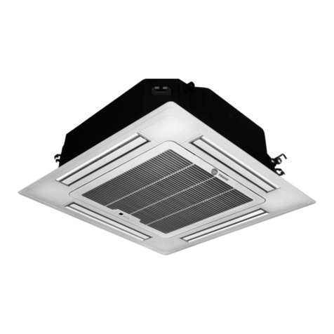
Trane FC User manual
Other Trane Air Conditioner manuals
Trane
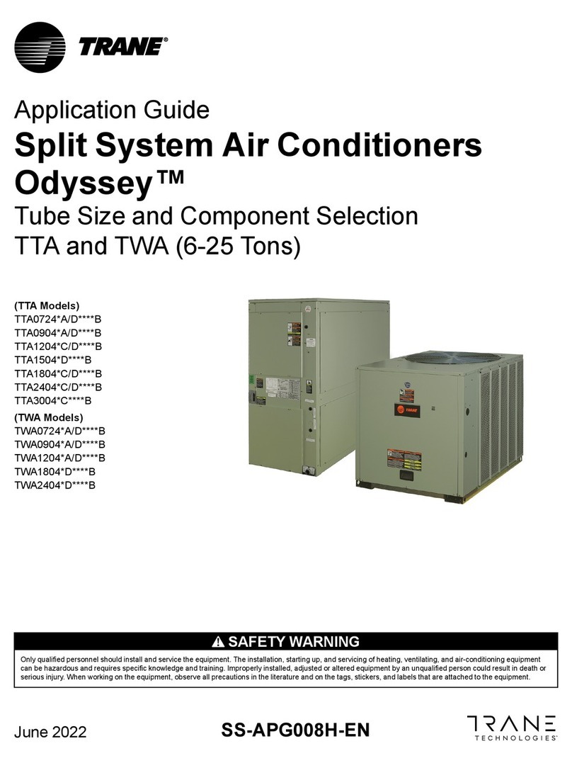
Trane Odyssey TTA0724 A Series User guide
Trane
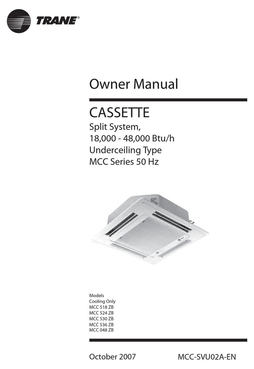
Trane MCC 536 ZB User manual
Trane
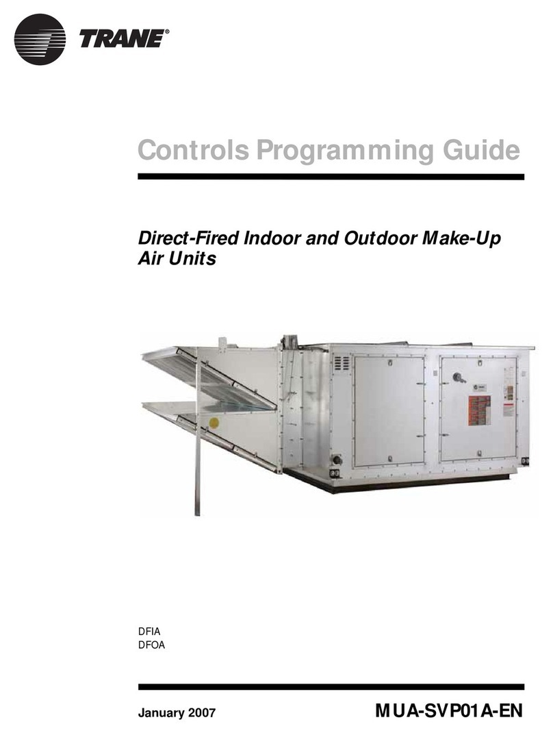
Trane DFIA Operating instructions

Trane
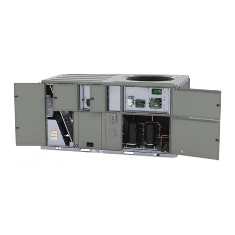
Trane YSC060 Owner's manual
Trane
Trane FIAECON102 Series User manual

Trane
Trane TTA090A series Owner's manual

Trane
Trane ComfortLink II 4TWL9024A1000B Assembly instructions

Trane
Trane CONTURA 3G CASSETTE User manual

Trane
Trane Packaged TerminalAir Conditioners & Heat... Owner's manual
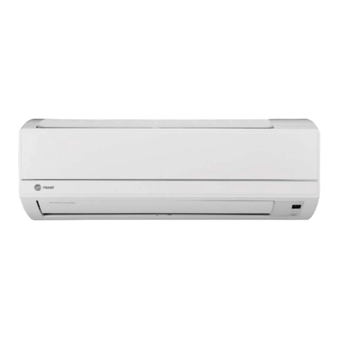
Trane
Trane R410a Operating manual
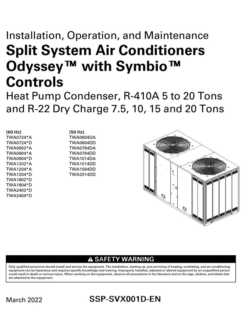
Trane
Trane TWA0724-A Series Installation and operating instructions

Trane
Trane XL16i Operation manual
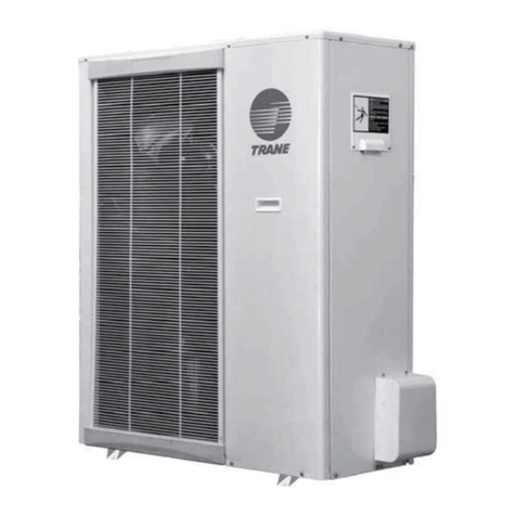
Trane
Trane TXUM524 Owner's manual
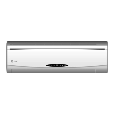
Trane
Trane 4MCW3-A User manual

Trane
Trane TTA240F Series Owner's manual
Trane
Trane ComfortLink II 4TWV0X24A1000A Assembly instructions
Trane
Trane 4TYK8536B1000AA Operating manual
Trane
Trane R410a User guide
Trane
Trane MXW Owner's manual
Trane
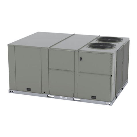
Trane Precedent DHJ150A Installation and operating instructions
Popular Air Conditioner manuals by other brands

CIAT
CIAT Magister 2 Series Installation, Operation, Commissioning, Maintenance

Bestron
Bestron AAC6000 instruction manual

Frigidaire
Frigidaire FFRE0533S1E0 Use & care guide

Samsung
Samsung AS09HM3N user manual

Frigidaire
Frigidaire CRA073PU11 use & care

Soleus Air
Soleus Air GB-PAC-08E4 operating instructions

McQuay
McQuay MCK020A Technical manual

Webasto
Webasto Frigo Top 25 DS Instructions for use

Frigidaire
Frigidaire FAZ12ES2A installation instructions

Mitsubishi Electric
Mitsubishi Electric MSC-GE20VB operating instructions

Mitsubishi Electric
Mitsubishi Electric PLA-M100EA installation manual

Daikin
Daikin Split Sensira R32 Service manual
