Transmille 3000A Series Use and care manual

TRANSMILLE LTD. Version 3 : Jun 2014 Page 1
3000A Series
Precision Multi Product Calibrator
Calibration Manual

3000A SERIES CALIBRATION MANUAL
TRANSMILLE LTD. Version 3 : Jun 2014 Page 2
TABLE OF CONTENTS
PREPARING FOR CALIBRATION ................................................................................................................ 3
INTRODUCTION .................................................................................................................................................. 3
EQUIPMENT REQUIRED ...................................................................................................................................... 3
OPTIONAL EQUIPMENT ...................................................................................................................................... 3
EQUIPMENT REQUIRED FOR OSCILLOSCOPE (SCPXXX) OPTION CALIBRATION ................................................. 4
EQUIPMENT REQUIRED FOR POWER (PWR50, PWRSINE, PWRDDS) OPTION CALIBRATION ........................... 5
CALIBRATION PASSWORD ........................................................................................................................... 6
CHANGING THE CALIBRATION PASSWORD ........................................................................................................ 6
SET NEW PASSWORD ......................................................................................................................................... 8
MANUAL CALIBRATION .............................................................................................................................. 10
ENTERING CALIBRATION MODE ...................................................................................................................... 11
EXITING CALIBRATION MODE ......................................................................................................................... 14
CALIBRATION PARAMETERS .................................................................................................................... 15
CONNECTIONS ............................................................................................................................................... 16
CALIBRATION OF RANGES ........................................................................................................................ 17
D.C. VOLTAGE ................................................................................................................................................ 17
D.C. CURRENT ................................................................................................................................................ 22
A.C. VOLTAGE ................................................................................................................................................ 27
A.C. CURRENT ................................................................................................................................................ 32
2WIRE Ω ......................................................................................................................................................... 37
4WIRE Ω ......................................................................................................................................................... 41
ACTIVE Ω ........................................................................................................................................................ 45
CAPACITANCE ................................................................................................................................................. 49
FREQUENCY OUTPUT ....................................................................................................................................... 53
INDUCTANCE ................................................................................................................................................... 54
PRT ................................................................................................................................................................. 58
OSCILLOSCOPE – AMPLITUDE .......................................................................................................................... 62
OSCILLOSCOPE – BANDWIDTH ......................................................................................................................... 67
AC POWER (CURRENT OUTPUT) ...................................................................................................................... 71
DC POWER (CURRENT OUTPUT) ...................................................................................................................... 76
A/D INPUT ....................................................................................................................................................... 81

3000A SERIES CALIBRATION MANUAL
TRANSMILLE LTD. Version 3 : Jun 2014 Page 3
Preparing For Calibration
Introduction
The recommended calibration period for the 3000A series calibrators is 12 months.
Extended specifications for 6, 12 and 24 month re-calibration periods are available
from the 3000A extended specifications
Calibration can be achieved using one of two methods:
1. Manual calibration via the front panel controls.
2. Automated closed-loop calibration using ProCal calibration software
In both instances the calibrator should be switched on and allowed to warm up for
the required period as stated in the operator’s manual. Calibration should be
performed in a stable environment where the temperature is stable to within +/- 1ºC
during the calibration.
Equipment Required
To calibrate the 3000A series calibrators the following equipment is required:
1. High Accuracy precision Multimeter (example Transmille 8081 / Agilent 3458A opt
002 / Fluke 8508A)
2. LCR Bridge (example Agilent
3. DC Voltage Source (example Transmille 3000 series multiproduct calibrator, Fluke
55xx series multiproduct calibrator
4. High Accuracy Frequency Counter / GPS Frequency Reference / Off-Air
Frequency Reference
Between these four pieces of equipment it is possible to calibrate all basic functions
of the 3000 series calibrators. For units fitted with additional options additional
equipment is required
Optional Equipment
To perform a full calibration of a 3000A series multiproduct calibrator additional
equipment may be required dependent upon the capabilities of the multimeter being
used

3000A SERIES CALIBRATION MANUAL
TRANSMILLE LTD. Version 3 : Jun 2014 Page 4
For multimeters such as the Agilent 3458A with limited maximum current, a selection
of current shunts are required. These current shunts should be suitable for both DC
and AC current up to 10kHz (5kHz for 2A Range, 1kHz for 30A range) Suggested
current shunt values are listed below, along with the current range they will be used
for :
0.1 Ohm – 2.02A to 30A AC/DC
1 Ohm – 202mA to 2A AC/DC
10 Ohm – 20.2mA to 200mA AC/DC
100 Ohm – 2.02mA to 20mA AC/DC
These shunts are also used for multimeters with insufficient current accuracy for low
current calibration.
Equipment required for Oscilloscope (SCPXXX)
option calibration
To calibrate the Oscilloscope output function of the 3000A series, the following
equipment is required
1. High Accuracy precision Multimeter
2. Frequency Counter / GPS Frequency Standard / Off-air Frequency Standard
3. 600MHz – 1GHz Oscilloscope (example Agilent Xfinity Series Oscilloscope)

3000A SERIES CALIBRATION MANUAL
TRANSMILLE LTD. Version 3 : Jun 2014 Page 5
Equipment required for Power (PWR50, PWRSINE,
PWRDDS) option calibration
To calibrate the Power output function of the 3000A series, the following equipment
is required
1. High Accuracy precision Multimeter
2. Phase Meter / Oscilloscope
3. Distortion Meter / Distortion Analyser (PWRDDS option only)

3000A SERIES CALIBRATION MANUAL
TRANSMILLE LTD. Version 3 : Jun 2014 Page 6
Calibration Password
Changing the Calibration Password
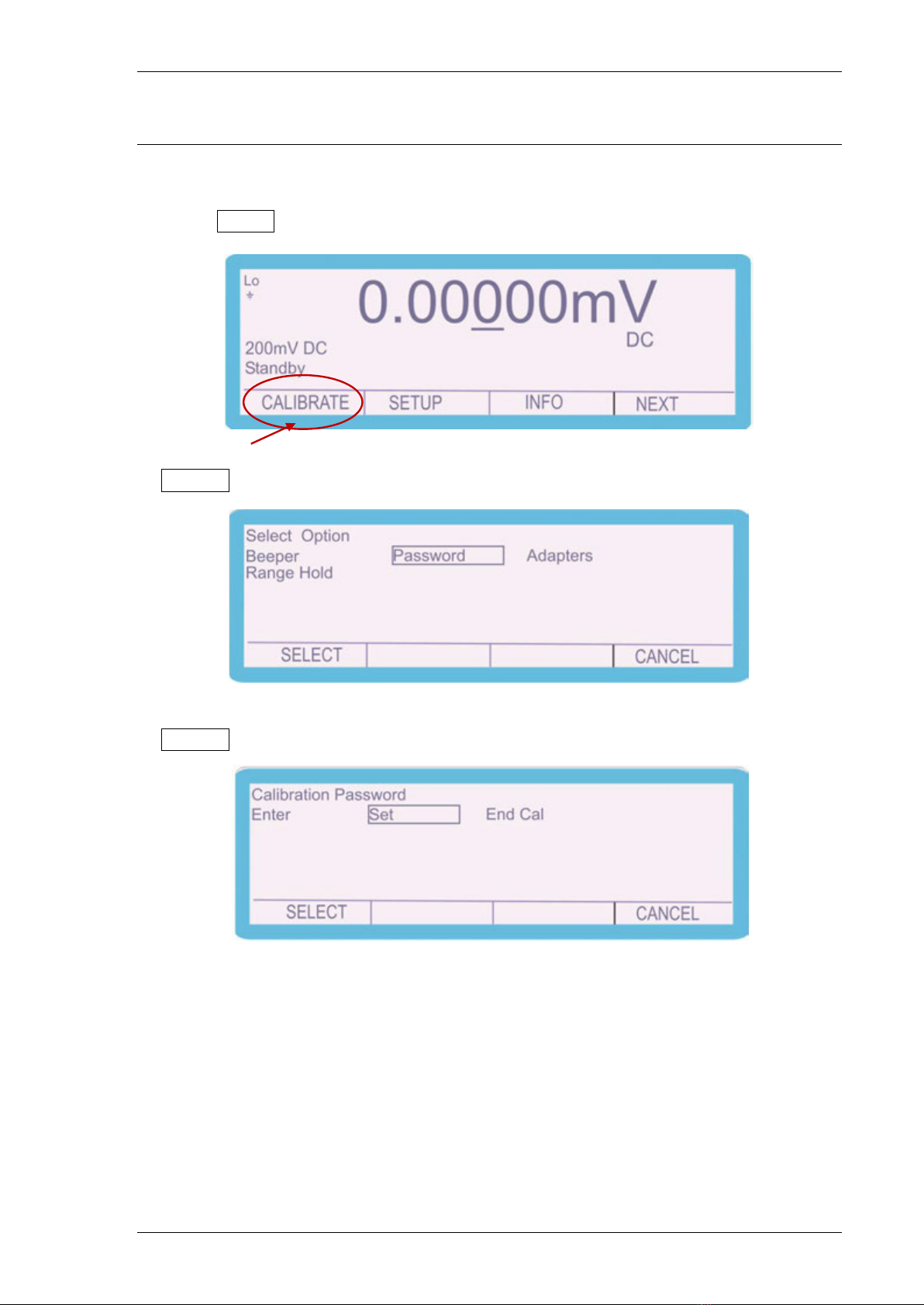
To navigate to the ‘Calibration Password’ screen follow the procedure in the section:
‘Manual Calibration’ to step 3 where the following screen appears:
1. Select SETUP using the soft key
2. Use the ‘Digital Control’ or the ‘Arrow Keys’ to highlight ‘Password’ and then press
SELECT soft key
3. Press SELECT soft key
4. Enter the calibration password (default 0324)

3000A SERIES CALIBRATION MANUAL
TRANSMILLE LTD. Version 3 : Jun 2014 Page 7
The following screen is displayed for approximately 2 seconds:
and then reverts to:
The instrument is now ready to be calibrated and the password can be changed.
3000A SERIES CALIBRATION MANUAL
TRANSMILLE LTD. Version 3 : Jun 2014 Page 8
Set New Password
To change the password, complete the following procedure:
1. Select SETUP using the soft key
2. Use the ‘Digital Control’ or the ‘Arrow Keys’ to highlight ‘Password’ and then press
SELECT soft key
2. Use the ‘Digital Control’ or the ‘Arrow Keys’ to highlight ‘Set’ and then press
SELECT soft key
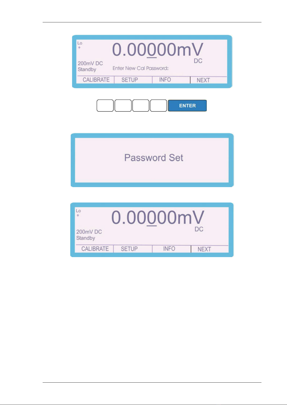
3. ‘Enter New Cal Password’ using function control keys, followed by the ENTER key
e.g. 3010
3000A SERIES CALIBRATION MANUAL
TRANSMILLE LTD. Version 3 : Jun 2014 Page 9
The following screen is displayed for approximately 2 seconds:
and then reverts to:
The password has now been changed.
3
0
1
0

3000A SERIES CALIBRATION MANUAL
TRANSMILLE LTD. Version 3 : Jun 2014 Page 10
Manual Calibration
Manual Calibration is achieved using the front panel control:
1. Digital control
2. Function control
3. Soft and Arrow keys
4. Range up and Down keys
5. Output On and Standby keys
Digital Control
1. Adjusts calibrator output
2. Selects calibrator ranges
3. Adjusts calibration factors
Function Control
1. Adjusts calibrator output
2. Enter ‘cal factors’
Soft and Arrow keys
1. Select parameter, range, store, undo & exit – (soft)
2. Change parameter and range (arrow)
Range keys
1. Changes calibration reference point on each range
Output On key – switches output on
Standby key – switches output off
3000A SERIES CALIBRATION MANUAL
TRANSMILLE LTD. Version 3 : Jun 2014 Page 11
Entering Calibration Mode
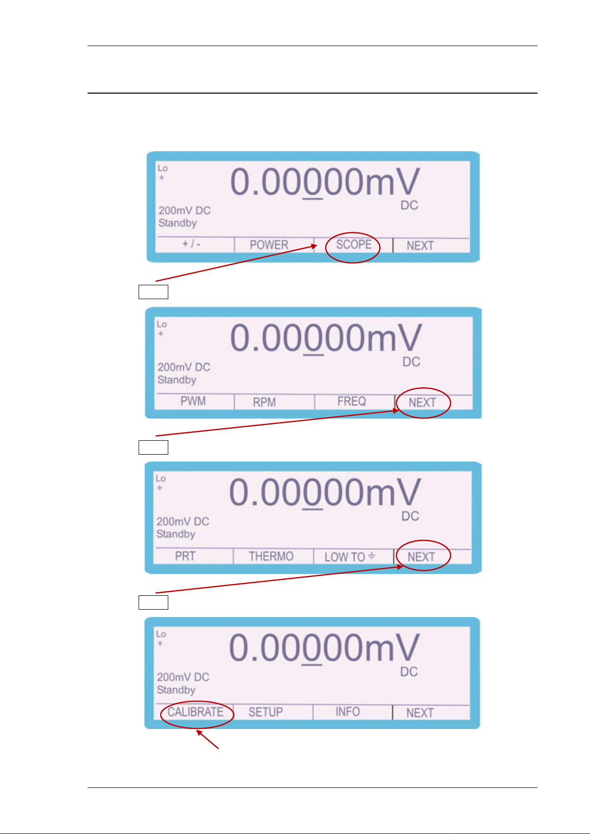
To navigate to the calibration control screen, complete the following procedure:
1. Select NEXT using the soft key
2. Select NEXT using the soft key
3. Select NEXT using the soft key
3000A SERIES CALIBRATION MANUAL
TRANSMILLE LTD. Version 3 : Jun 2014 Page 12
4. Select CALIBRATE using the soft key
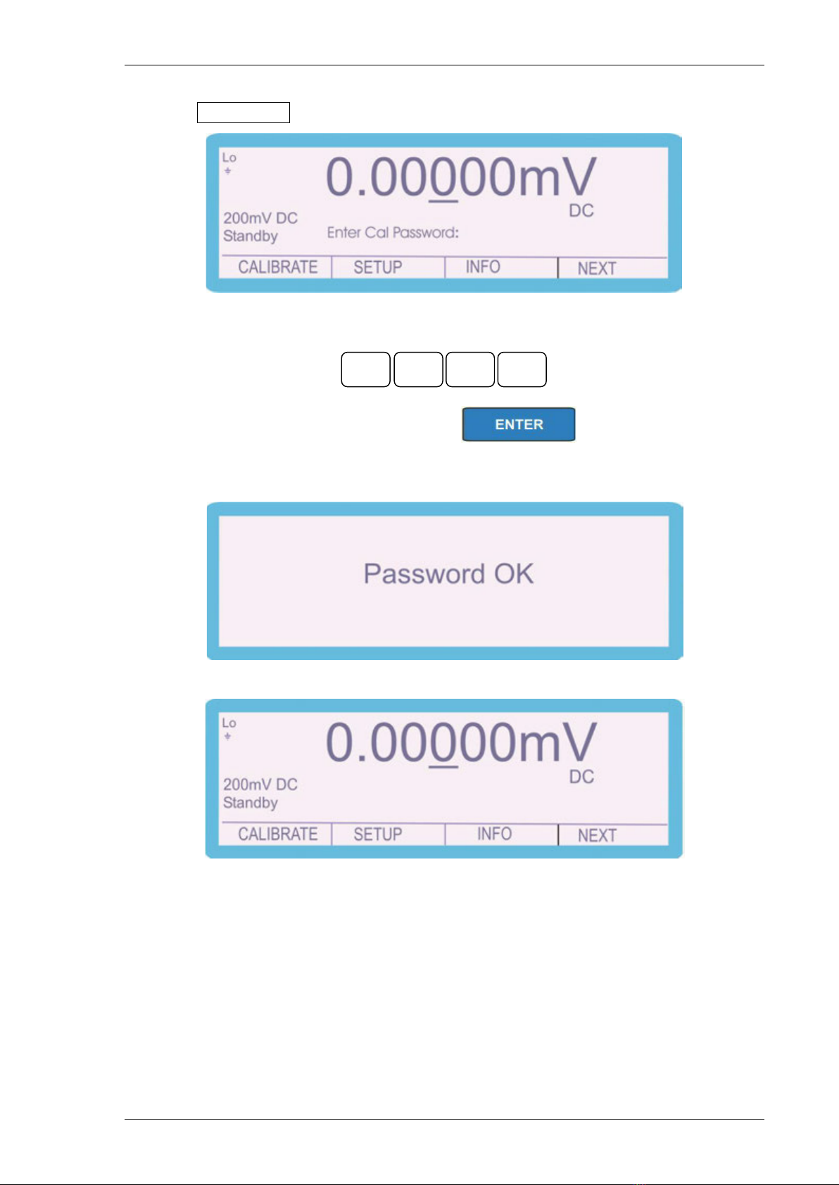
5. ‘Enter Cal Password’ using function control keys
(0324 is the default password) followed by
The following screen is displayed for approximately 2 seconds:
and then reverts to:
The instrument is now ready to be calibrated.
0
0
3
2
4
3000A SERIES CALIBRATION MANUAL
TRANSMILLE LTD. Version 3 : Jun 2014 Page 13
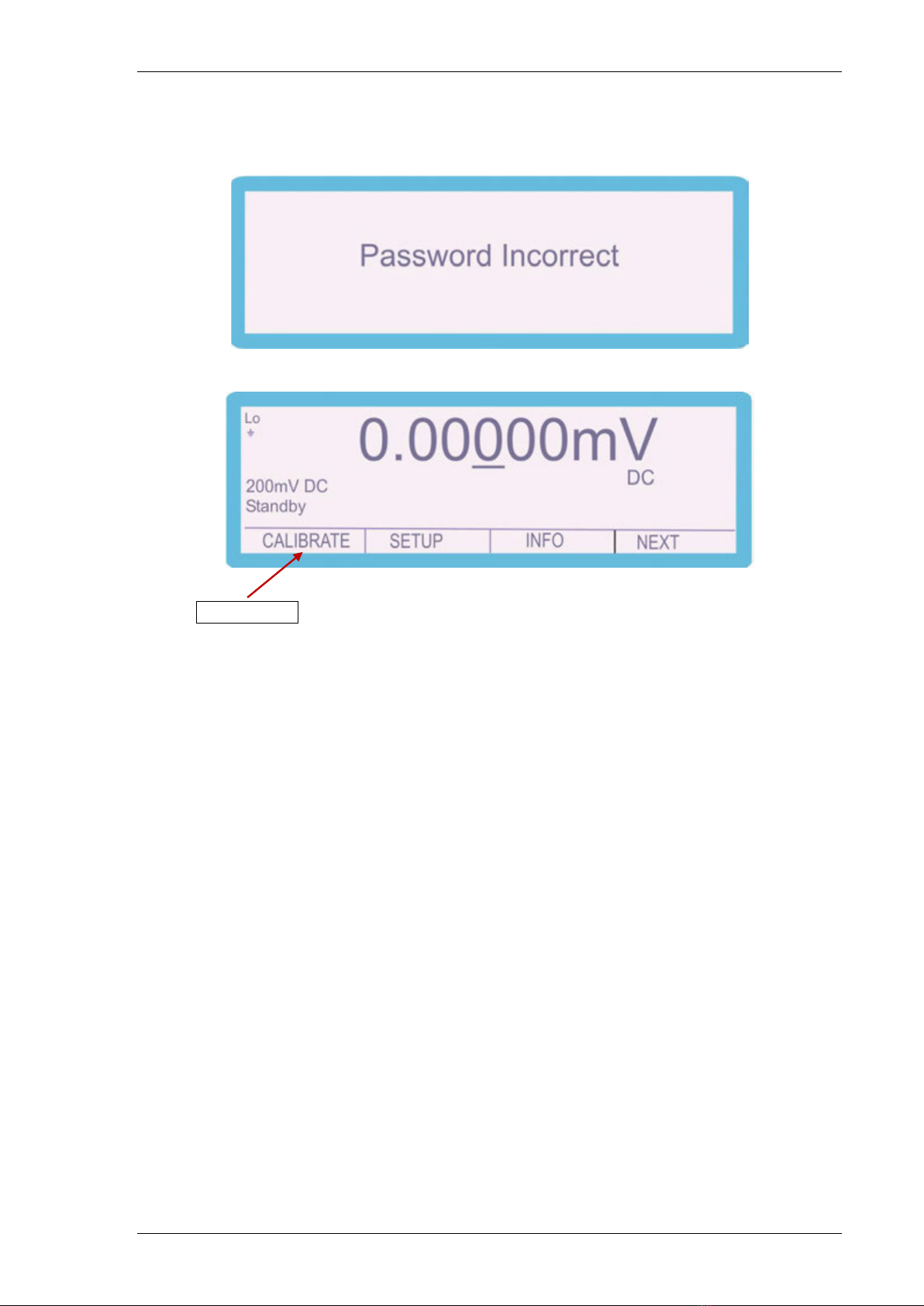
Should the password be entered incorrectly the screen will display
for approximately 2 seconds and then reverts to:
Select CALIBRATE using the soft key to navigate back to ‘Enter Cal Password’
screen and re-enter the password.

3000A SERIES CALIBRATION MANUAL
TRANSMILLE LTD. Version 3 : Jun 2014 Page 14
Exiting Calibration Mode
After calibration of the 3000A series is complete the calibration program should be
ended to avoid any unauthorised or mistaken adjustment of the calibrator.
The following procedure should be completed.
1. Select SETUP using the soft key
2. Use the ‘Digital Control’ or the ‘Arrow Keys’ to highlight ‘Password’ and then press
SELECT soft key
3. Use the ‘Digital Control’ or the ‘Arrow Keys’ to highlight ‘End Cal’ and then press
SELECT soft key
The calibrator returns to the normal screen.

3000A SERIES CALIBRATION MANUAL
TRANSMILLE LTD. Version 3 : Jun 2014 Page 15
Calibration Parameters
With the calibration password entered the different parameters of the instrument can
be calibrated:
To enter the different parameters, complete the following procedure:
1. Select CALIBRATE using the soft key
2. Use the ‘Digital Control’ or the ‘Arrow Keys’ to highlight the required parameter
e.g. ‘DC Volts’ and then press SELECT soft key
Depending upon the model and options fitted the available functions will vary
3000A SERIES CALIBRATION MANUAL
TRANSMILLE LTD. Version 3 : Jun 2014 Page 16
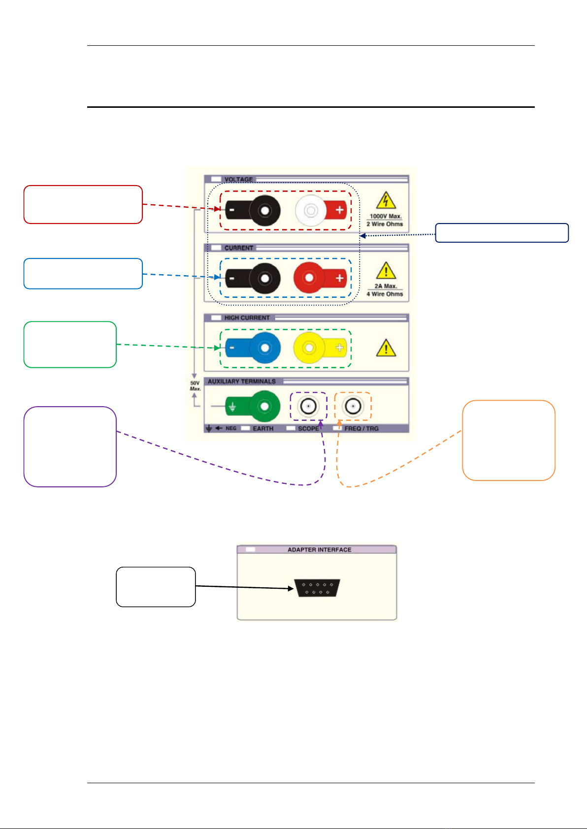
Connections
The output of the 3000A series calibrator should be connected to the precision
multimeter as below :
DC & AC Voltage, 2 Wire ,
Capacitance, Inductance,
Active
DC & AC Current up to and
including the 2A range
DC & AC Current
20A range - 3050A
30A range - 3041A
& 3010A
Oscilloscope
Amplitude,
Bandwidth,
50kHz Reference
DC & AC Power, 4 Wire PRT
A/D Input
Pin 7 – ground
Pin 9 - Input
Frequency Output
1Hz – 10MHz
frequency output
3000A SERIES CALIBRATION MANUAL
TRANSMILLE LTD. Version 3 : Jun 2014 Page 17
Calibration of Ranges
D.C. Voltage
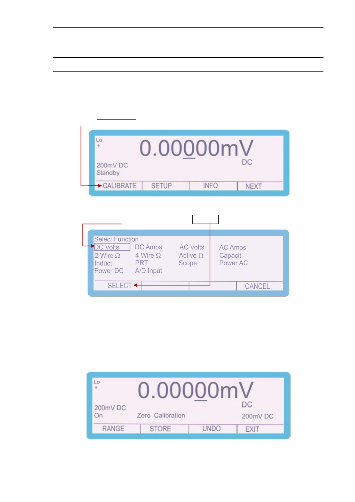
To calibrate the D.C. Voltage parameter, complete the procedure as follows:
1. Select CALIBRATE using the soft key
2. Use the ‘Digital Control’ or the ‘Arrow Keys’ to highlight the required
parameter ‘DC Volts’ and then press SELECT soft key
3. Connect the calibrator output voltage terminals to the precision Multimeter.
Ensure that the Multimeter has been zeroed as a system by shorting out the
leads and pressing the null button.
4. Use the ‘range up’ and ‘range down’ keys to change the calibration point to
‘Zero Calibration’.
3000A SERIES CALIBRATION MANUAL
TRANSMILLE LTD. Version 3 : Jun 2014 Page 18
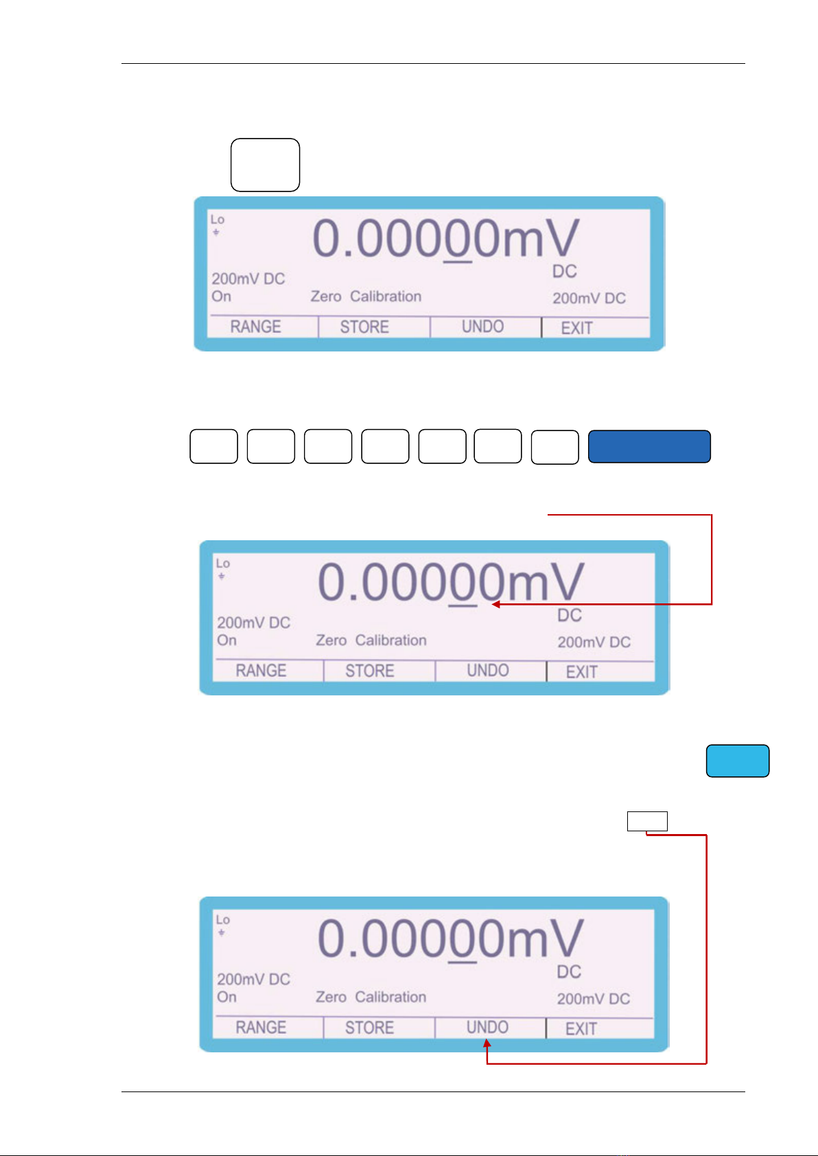
5. Press and measure the output ‘Zero Calibration’.
6. To adjust the output, type in the measured value using the keyboard, followed
by the ‘ENTER’ key i.e. 0.00028mV
7. The output can also be adjusted by moving the ‘cursor’ to the required digit
and adjusting the output using the up / down arrows or the digital control
8. The ‘SHIFT’ key will illuminate to indicate that a change has been made
to the calibration of the instrument, however has not yet been stored.
9. To undo the adjustment before storing the changes, press the UNDO soft key.
This will remove any changes that have been made to the output of the
calibrator.
SHIFT
OUTPUT
ON
0
•
0
0
0
2
8
ENTER

3000A SERIES CALIBRATION MANUAL
TRANSMILLE LTD. Version 3 : Jun 2014 Page 19
10. Once the output has been adjusted to within specification, the changes can be
stored to long term memory. To store the changes permanently, press the
STORE soft key
The following 2 screens are displayed briefly to confirm that the calibration
factors have been saved.
After displaying these messages, the shift key will also cease to be illuminated
11. Using the ‘RANGE UP’ and ‘RANGE DOWN’ keys, change the output to
‘Positive Full Scale’
SHIFT
Note: All the calibration points can be adjusted prior to storing the
calibration factors (STORE), however if the calibration routine is
ended or there is a power failure the new calibration factors will not
be saved if STORE has not been pressed.

3000A SERIES CALIBRATION MANUAL
TRANSMILLE LTD. Version 3 : Jun 2014 Page 20
12. Measure the output, and adjust as required using the process described in
steps 6 - 10
13. Use the ‘range up’ and ‘range down’ keys to change the calibration point to
‘Negative Full Scale’.
14. Measure the output, and adjust as required using the process described in
steps 6 - 10
15. When calibration of this range is complete press the RANGE soft key
16. To continue adjusting other ranges in the DC Voltage function, select ‘DC
Volts’ and select the required range
This manual suits for next models
3
Table of contents
Other Transmille Test Equipment manuals

Transmille
Transmille 4610M User manual

Transmille
Transmille 3200A Series User manual

Transmille
Transmille 5080 User manual

Transmille
Transmille 1000 Series User manual

Transmille
Transmille 9000 Series User manual

Transmille
Transmille 2100 Use and care manual

Transmille
Transmille 4610M Use and care manual

Transmille
Transmille 4610M Owner's manual

Transmille
Transmille 3000 Series Use and care manual

Transmille
Transmille 1000 Series Use and care manual


