TECHNICAL MANUAL: BINDING BETWEEN GWA1531 AND GWA1501 | ZIGBEE | page 9
CONFIGURATION
If the ZigBee network hasn't yet been created, proceed as follows:
1. Choose which device will have the role of coordinator
2. Activate the procedure to create the ZigBee network via the coordinator
3. After creating the network, activate Permit Join
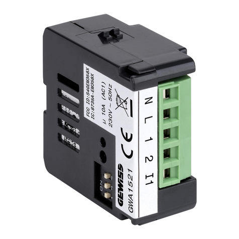
4. Power the devices that you want to join to the network (GWA1531 and GWA1501)
5. Make the binding between the GWA1531 and GWA1501 devices
If the ZigBee network has already been created, only the last three points of the list are required:
1. After creating the network, activate Permit Join
2. Power the devices that you want to join to the network (GWA1531 and GWA1501)
3. Make the binding between the GWA1531 and GWA1501 devices
Creating and joining to the ZigBee network:
1. Make sure the actuator is in its factory-set condition (if it isn't, make a factory reset)
2. The LED on the device must have a fixed red light
3. Press the Permit Join activation button key quickly for 3 times. The LED will turn green for a few
seconds and then begin flashing. From this moment, Permit Join is activated for 15 minutes (this
device is now the network coordinator).
4. Make sure the interface is in its factory-set condition (if it isn't, make a factory reset)
5. When the device is powered, a scan will be launched (red LED) to identify an open ZigBee network
6. When the association has been made, the status LED will begin flashing red (or it will switch off)
7. Briefly press the button key of the actuator (network coordinator) to close the network
Association between devices:
1. On the GWA1531 actuator, bring the dip-switches to the positions shown:
The status LED will have a fixed yellow light
2. Press the push-button connected to local input I▲ on the actuator. The status LED will make a
double yellow flash and this will continue cyclically
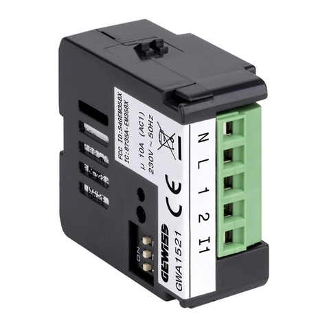
3. On the GWA1501 interface, bring the dip-switches to the position
4. The status LED will turn yellow
5. Now use the button key connected to the interface that you want to associate (I1 or I2)
6. Repeat the operation from point 2 (always with the input on the actuator) to add the button key not
yet joined (I2) (if present)
7. The identification phase will normally terminate automatically (the LED will have a fixed yellow light
again). If this doesn't happen, wait 3 minutes.
8. Set the dip-switches on the basis of the functions required
