Tregaskiss G1 Series Quick start guide

TECHNICAL GUIDE
TOUGH GUN™ThruArm™
G1 Series Robotic MIG
Guns for KUKA® Robots
KR 5 arc HW
INSTALLATION
MAINTENANCE
TECHNICAL DATA
OPTIONS
EXPLODED VIEW & PARTS
LIST
ORDERING INFORMATION
Certified ISO 9001 : 2008
Please read instructions prior to use.
Save this manual for future reference
Effective September 2010 –
QUICK LOAD™Liners Standard
on all TOUGH GUN™ Robotic MIG Guns

2
TABLE OF CONTENTS
THANK YOU..............................................................................................................................................................2
GENERAL SAFETY INFORMATION........................................................................................................................3
WARRANTY .............................................................................................................................................................. 3
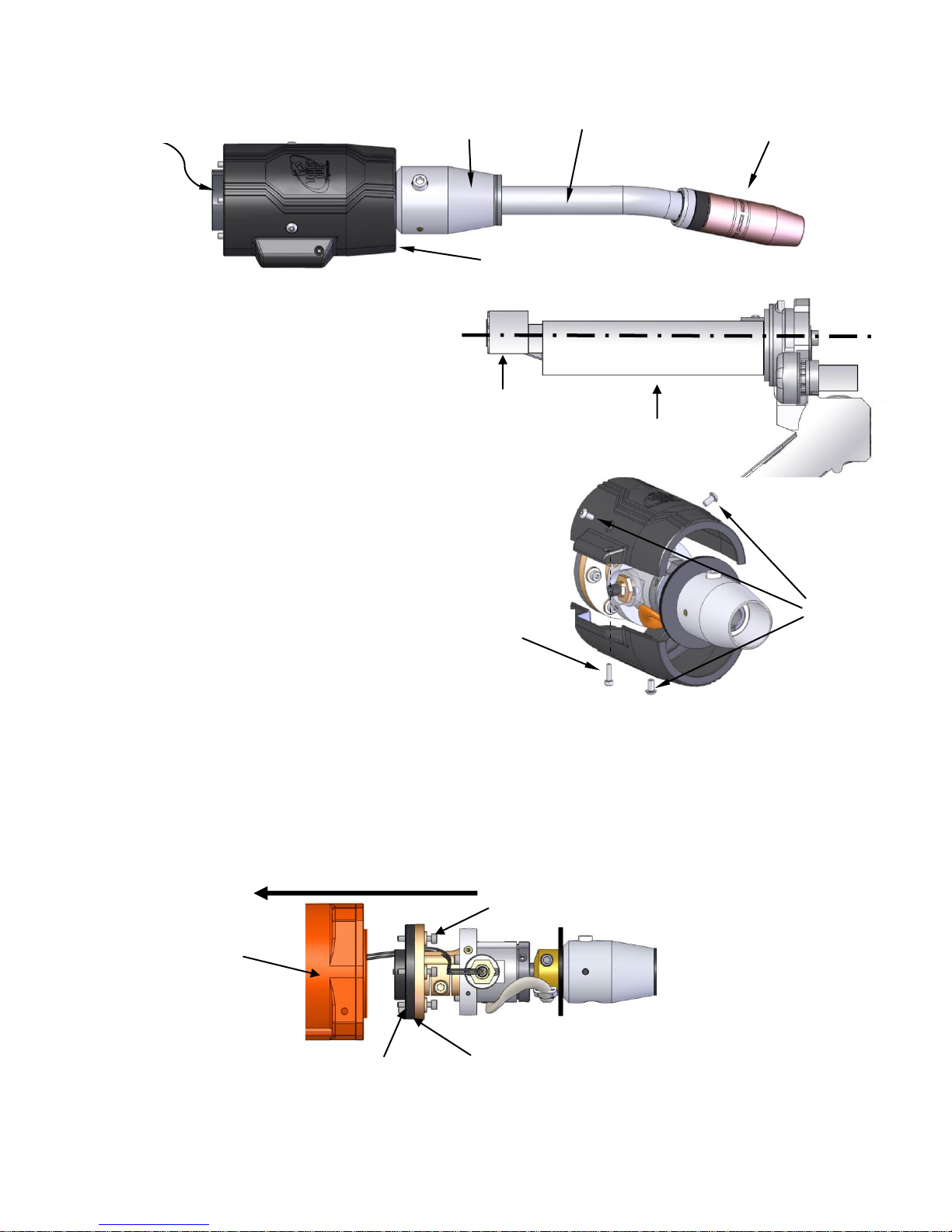
1.0 –COMPLETE ASSEMBLY OVERVIEW.............................................................................................................4
2.0 –INSTALLATION................................................................................................................................................5
STEP #1 - POSITIONING THE ROBOT ................................................................................................................5
STEP #2 - REMOVING OUTER COVER...............................................................................................................5
STEP #3 - INSTALLING GUN TO ROBOT............................................................................................................5
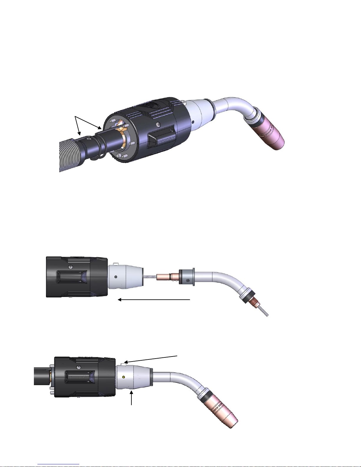
STEP #4 - CONNECTING LSR UNICABLE...........................................................................................................6
STEP #5 - INSTALLING NECK..............................................................................................................................6
STEP #6 - INSTALLING POWER PIN TO THE LSR UNICABLE..........................................................................7
STEP #7 - INSTALLING QUICK LOAD LINER......................................................................................................7
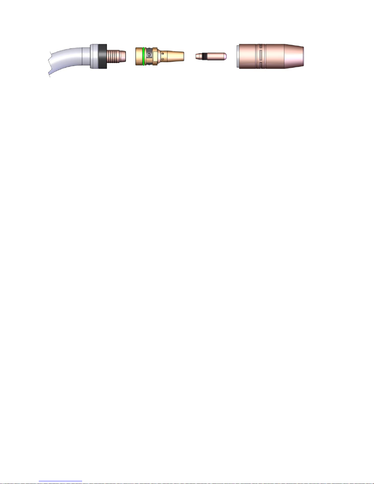
STEP #8 - INSTALLING CONSUMABLES ............................................................................................................8
STEP #9 - INSTALLING GUN TO WIRE FEEDER................................................................................................8
3.0 –MAINTENANCE................................................................................................................................................9
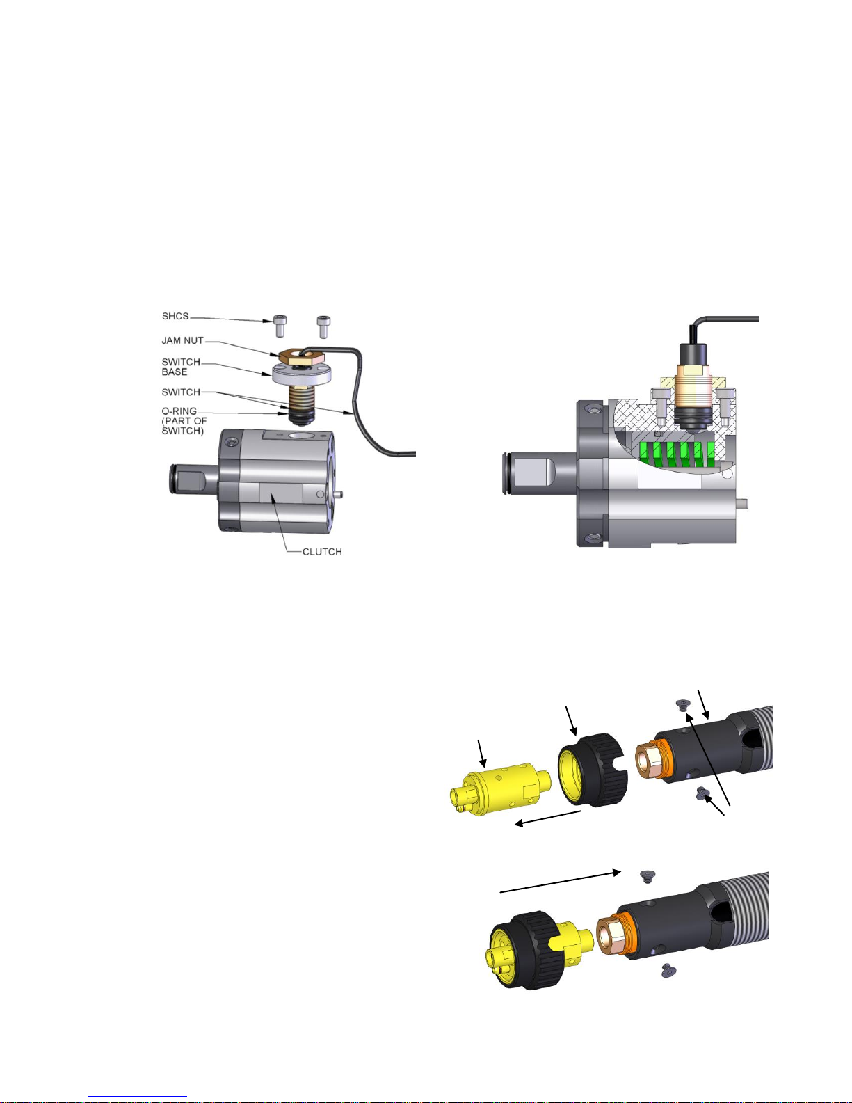
3.1 REPLACEMENT / ADJUSTMENT OF CLUTCH LIMIT SWITCH...................................................................9
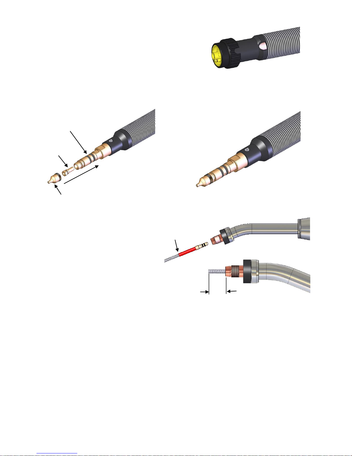
3.2 REPLACEMENT OF EURO CONNECTION...................................................................................................9
3.3 REPLACEMENT OF QUICK LOAD™LINER................................................................................................10
4.0 –TECHNICAL DATA ........................................................................................................................................11
4.1 GUN CONFIGURATIONS.............................................................................................................................11
4.2 CENTER OF MASS.......................................................................................................................................11
4.3 AMPERAGE RATINGS*................................................................................................................................12
5.0 –EXPLODED VIEW & PARTS LIST –K5800..................................................................................................12
6.0 –PARTS LISTS FOR K5800A, K5800W, & K5800AW MODELS...................................................................13
6.1 WIRE BRAKE FOR K5800W MODELS........................................................................................................13
6.2 AIR BLAST FOR K5800A & K5800AW MODELS........................................................................................13
7.0 –ORDERING INFORMATION ..........................................................................................................................14
THANK YOU...
…for selecting a Tregaskiss TOUGH GUN™ ThruArm™G1 Series Robotic MIG Gun. Manufacturing operations
demand extremely dependable robotic equipment. With this in mind, the TOUGH GUN™MIG Gun was designed
and engineered to be a reliable tool to support high production within a robotic cell. As the name implies, the
TOUGH GUN MIGGun is made from durable materials and components engineered to perform in a rugged
welding environment. Your TOUGH GUN MIG Gun is completely assembled and ready to weld, and has
undergone numerous quality checks to ensure high performance.
The instructions and illustrations in this technical guide make it easy for you to maintain your TOUGH GUN
Robotic MIG Gun. Please read, understand, and follow all safety procedures. Keep this Technical Guide
booklet as a handy reference when ordering complete guns, parts and special options. For technical support
and special applications, please call the Tregaskiss Technical Service Department at 1-855-MIGWELD
(644-9353) or fax 1-877-737-2111. Our trained technicians are available between 8:00 a.m. and 5:00 p.m. EST,
and will answer your application or repair questions.
Tregaskiss employees build TOUGH GUN MIG Guns for the world’s welding professionals. We are always
striving to improve our products and services, and would appreciate receiving your suggestions or comments.
Please contact us immediately if you experience any safety or operating problems.

3
GENERAL SAFETY INFORMATION
Before installation or operation of TOUGH GUN MIG Guns, please read the safety precautions listed below.
1. Do not touch live electrical parts. The following should be checked to prevent electrical shock:
Faulty or damaged equipment is repaired or replaced.
Equipment is off when not in use.
2. Ensure that all safety devices, guards, shields or barriers are properly in place and connected correctly before
allowing operation of the equipment.
3. CSA Standard W117.2 CODE FOR SAFETY IN WELDING AND CUTTING obtainable from the Canadian
Standards Association, Standards Sales, 178 Rexdale Boulevard, Rexdale, Ontario, Canada M9W 1R3.
ANSI Standard Z49.1 CODE FOR SAFETY IN WELDING AND CUTTING obtainable from the American
National Standards Institute, 1430 Broadway, New York, NY 10018.
CALIFORNIA PROPOSITION 65 WARNING
This product, when used for welding or cutting, produces fumes or gases which contain chemicals known to the
State of California to cause birth defects and, in some cases, cancer.
This product contains chemicals, including lead, known to the State of California to cause cancer, and
birth defects or other reproductive harm. Wash hands after use.
(California Health & Safety Code Section 25249.5 at seq.)
WARRANTY
Product is warranted to be free from defects in material and workmanship for the period specified below after the
sale by an authorized Buyer. Should there be a defect please refer to our Return Merchandise Policy.
PRODUCT
WARRANTY PERIOD
TOUGH GUN™ Robotic MIG Guns and Components
180 days
TOUGH GUN Reamer
1 year
TOUGH GARD™Spatter Cleaner
1 year
TOUGH GUN Robotic Peripherals (Clutch, Sprayer, Wire Cutter, Mounting Arms)
1 year
Low-Stress Robotic Unicables (LSR Unicables)
2 years
Tregaskiss reserves the right to repair, replace or refund the purchase price of non-conforming product. Product
found not defective will be returned to the Buyer after notification by Customer Service.
Tregaskiss makes no other warranty of any kind, expressed or implied, including, but not limited to the warranties
of merchantability or fitness for any purpose. Tregaskiss shall not be liable under any circumstances to Buyer, or
to any person who shall purchase from Buyer, for damages of any kind including, but not limited to any, direct,
indirect incidental or consequential damages or loss of production or loss of profits resulting from any cause
whatsoever, including, but not limited to, any delay, act, error or omission of Tregaskiss.
Genuine Tregaskiss™parts must be used for safety and performance reasons or the warranty becomes invalid.
Warranty shall not apply if accident, abuse, or misuse damages a product, or if a product is modified in any way
except by authorized Tregaskiss personnel.

4
1.0 –COMPLETE ASSEMBLY OVERVIEW
For part numbers, please see Section 6.0 EXPLODED VIEW AND PARTS LIST.
LSR UNICABLE
RETAINING HEAD
THRUARM CLUTCH
ASSEMBLY
POWER
PIN
QUICK
LOAD™
LINER AND
RETAINER
NECK
CONTACT TIP
NOZZLE

5
2.0 –INSTALLATION
STEP #1 - POSITIONING THE ROBOT
Position the robot with the wrist and top axis
as shown to properly complete the gun
installation.
STEP #2 - REMOVING OUTER COVER
Unthread (3) M4 SBHCS, using a 2.5 mm
Allen key.
Unthread (1) M3 SHCS, using a 2.5 mm
Allen key and pull apart both cover halves.
Insulating disc should remain in place,
located by dowel.
STEP #3 - INSTALLING GUN TO ROBOT
Locate assembly onto robot mounting face using dowel pin as a guide.
Insert M4x20 (x6) bolts through insulating disc and mounting flange into robot face. Thread bolts
clockwise using a 3 mm ball-nose Allen key (ball end) to 45 in.-lbs. (5 Nm).
Re-install Outer Cover in reverse order of instruction in STEP #2.
M4 x 8 SBHCS
M3 x 6 SHCS
NECK
OUTER COVER
INSULATING DISC
CONNECTOR
HOUSING
CONSUMABLES
M4X20 BOLTS
DOWEL
INSULATING
DISC / MOUNT
FLANGE
ROBOT
WRIST
TOP AXIS

6
STEP #4 - CONNECTING LSR UNICABLE
Insert Unicable through mounting face of robot (cutaway of robot shown below).
Insert Unicable Connector into flange-cable connector. Ensure components are fully seated. Tregaskiss
Low Stress Robotic Unicable shown here (See Section 2.0 INSTALLATION)
Secure by tightening M6x20 SHCS, using 5 mm Allen key to 80 in.-lbs. (9 Nm).
Connect wire connectors (non polarity specific).
IMPORTANT: Leave slack loop around flange for articulation.
STEP #5 - INSTALLING NECK
Insert new neck over the liner and into connector housing until neck is fully seated.
Once fully seated and secured into place, see STEP #7 for liner trimming instructions.
NOTE: For best results, install the neck without the consumables so that the liner can pass through
easily.
Tighten Neck bolt clockwise with 5 mm Allen key to torque specifications (60 in.-lbs. or 7Nm).
IMPORTANT: Do not over-tighten bolt or damage may occur.
CONNECTOR HOUSING
NECK BOLT
SLACK LOOP
NOTE: ROBOT
REMOVED FOR CLARITY

7
STEP #6 - INSTALLING POWER PIN TO THE LSR UNICABLE
Option #1 of 2: Power Pins
Install power pin onto the LSR Unicable.
NOTE: Power pins incorporate a taper to seat
and lock the pin to the rear handle block. Make
sure the power pin is tightened in the block with
a wrench to insure the pin is secure and will not
come loose.
oThread power pin into the adapter of
the LSR Unicable.
oTighten the power pin into the rear
block using a 1” (25 mm) wrench on
the rear block and a 5/8” (16 mm) or
3/4” (19 mm) wrench on the power pin.
Option #2 of 2: Euro Connection
The Euro connection comes factory installed.
No installation required.
STEP #7 - INSTALLING QUICK LOAD LINER
Remove the rear cap of the power pin.
Insert brass end of liner into the liner retainer until firmly seated.
Insert non-brass end of QUICK LOAD™Liner into back of the gun and push through until it emerges from the
front of the gun and the liner retainer makes contact with the
power pin.
Thread the QUICK LOAD Liner retainer (#415-26) into the
power pin. Torque to 30 in.-lbs. (3.5 Nm).
Re-thread the cap of the power pin back on (hand tighten).
Push liner back into front of gun and hold in place.
Trim liner to a 5/8” (16 mm) stick out.
Remove any burrs that may obstruct wire feed.
POWER PIN
(MILLER SHOWN)
5/8”
LINER
RETAINER
REAR CAP
POWER PIN
(MILLER SHOWN)

8
NECK
RETAINING
HEAD
TOUGH LOCK
CONTACT TIP
NOZZLE
STEP #8 - INSTALLING CONSUMABLES
Retaining Head
Thread the retaining head onto the neck.
Use a 5/8” wrench and tighten to 80 in.-lbs. (or 9 Nm).
Contact Tip
Thread the contact tip into the retaining head.
Torque to 30 in.-lbs. (3.5 Nm).
Nozzle
Press the slip-on TOUGH GUN Nozzle over the retaining head/contact tip combo until the nozzle is
fully seated.
IMPORTANT: Be sure all consumables are tightened properly and fully seated before welding to
prevent overheating.
STEP #9 - INSTALLING GUN TO WIRE FEEDER
Feed the cable through the hole in the body of the robot.
Install the control cable (for LSR Systems with Clutches ONLY).
oConnect the jumper control cable to the main control cable of the LSR System.
oConnect to the wire feeder as per the manufacturer’s instructions.
Install into wire feeder as per the manufacturer’s instructions.

9
3.0 –MAINTENANCE
3.1 REPLACEMENT / ADJUSTMENT OF CLUTCH LIMIT SWITCH
Feed wires of switch through center holes of switch base and jam nut as shown in exploded view.
Thread switch base far enough down on the switch body so that the switch will not bottom out when the
assembly is fastened to the clutch.
Position switch assembly (with o-ring) in the clutch housing.
Insert the two M3 x 0.5 x 6 Hex SHCS into the holes in the switch base and fasten assembly to the clutch.
Adjust switch by rotating switch itself in the switch base to the appropriate depth. Check normally closed
switch using ohmmeter to set desired level of sensitivity.
Once desired sensitivity is achieved, lock position of switch by torquing jam nut (50 in.-lbs./5.6 Nm)
against switch base.
EXPLODED VIEW
FINISHED ASSEMBLY
3.2 REPLACEMENT OF EURO CONNECTION
Remove M5 x 6mm countersunk
fasteners.
Slide the hand nut over the Euro power
pin body.
Torque the power pin body to the
threaded end of the unicable at 18 ft.-lbs.
(24 Nm) using 7/8” & 13/16” wrenches.
You may have to pull back on the outer
conduit to achieve this.
Once the power pin body is in place, pull
the conduit down over it. Rotate the
conduit so that the holes on the power pin
line up with the holes on the plastic end of
the conduit.
HAND NUT
POWER
PIN
BODY
CONDUIT
M5 x 6mm
SCREWS

10
Insert the two M5 x 6mm countersunk
screws and torque to 12 in.-lbs. (1.35
Nm). You may have to rotate the hand nut
to access the holes.
3.3 REPLACEMENT OF QUICK LOAD
™LINER
Remove the rear cap of the power pin.
Remove the QUICK LOAD Liner retainer (#415-
26) from the power pin and thread in new one.
Torque to 30 in.-lbs. (3.5 Nm). NOTE: One liner
retainer can last for multiple liner replacements.
Therefore this step is not required for every liner
change.
Re-thread the cap of the power pin back on
(hand tighten).
Next, install QUICK LOAD Liner through front of
gun (neck).
Ensure liner is completely seated in retainer at
rear of cable.
Push liner back into front of gun and hold in
place.
Trim liner to a 5/8” (16 mm) stick out.
Remove any burrs that may obstruct wire feed.
QUICK
LOAD
LINER
5/8”
POWER PIN
(MILLER SHOWN)
LINER
RETAINER
REAR CAP

11
4.0 –TECHNICAL DATA
4.1 GUN CONFIGURATIONS
22° Neck –0.59” (15 mm) CTWD
45° Neck –0.59” (15 mm) CTWD
4.2 CENTER OF MASS
**WITH 0.59” (15 mm) WIRE STICKOUT
22° NECK
45° NECK
X
0.14"
(3.60 mm)
0.33"
(8.38 mm)
Y
0
0
Z
-4.9"
(124.46 mm)
-4.65"
(-118.11 mm)
WEIGHT
3.94 lbs.
(1.79 kg)
3.89 lbs.
(1.76 kg)
TCP REF.
DIM. "A"**
15.84"
(402.34 mm)
13.96"
(354.58 mm)
TCP REF.
DIM. "B"**
1.85"
(46.99 mm)
3.95"
(100.33 mm)

12
4.3 AMPERAGE RATINGS*
MODEL
60% DUTY CYCLE - MIXED GASES
OR 100% DUTY CYCLE - CO2
TOUGH GUN ThruArm Series –Air-Cooled
500 amp
*Ratings are based on tests that comply with IEC 60974-7 standards.
5.0 –EXPLODED VIEW & PARTS LIST –K5800
PART #
DESCRIPTION
PART #
DESCRIPTION
1
401-X-XX
Nozzle
11
580-18
Flange Cable Connector Set
2
403-XX-35
Contact Tip - 0.035 Wire
12
AS-114-6
Insulating Disc
403-XX-45
Contact Tip - 0.045 Wire
13
58CK021
LSR Unicable for KUKA KR5 ARC
HW
3
404-XX
Retaining Head
14
Control Cable (Comes with LSR
Unicable)
4
402-11
Neck Insulator
15
AS-714
Clutch Assembly
5
405-22QC
Neck 22 Degree
16
580-3
Lock Pin and Screw
405-45QC
Neck 45 Degree
17
580-2-3
Rubber Washer
6
M4X.7X8 LG S.B.H.C.S.
18
580-2
Connector Housing
7
580-5A
Outer Cover –Air-Cooled (Kit
Includes Items 6, 20)
19
580-4
Shunt Cable Assembly
8
AS-714-9
Clutch Switch Assembly
20
M3X.5X12 LG S.H.C.S.
9
AS-114-3
Mounting Ring Assembly
10
M4X.7X20 LG S.H.C.S.

13
6.0 –PARTS LISTS FOR K5800A, K5800W, & K5800AW MODELS
6.1 WIRE BRAKE FOR K5800W MODELS
NOTE: Wire brake can only be used if gun was originally ordered with wire brake option. The QUICK LOAD
Liner is not offered for Wire Brake gun assemblies.
6.2 AIR BLAST FOR K5800A & K5800AW MODELS
NOTE: Run Air Blast Line through the same hole as the Control Cable. See Technical Guide
Addendum M076 Air Blast Installation for ThruArm Series Robotic MIG Guns on our website at
www.tregaskiss.com for details or call Tech Services at 1-877-737-3111 for assistance.
PART #
DESCRIPTION
580-A
Air Blast Kit (Includes 15’ of Air Line and Air Fitting)
ITEM
PART #
DESCRIPTION
1
450-17
Holder Tool
2
495-18-35
Jump Liner for ≤0.045”
495-18-116
Jump Liner for ≥0.052”
3
499-045
Pushing Unit for up to 0.045” Wire
499-116
Pushing Unit for 0.052” to 1/16” Wire
4
499-9-15
Air Line 15’
5
598
Holder for ≤0.045”
598-116
Holder for ≥0.052”
AIR LINE
AIR FITTING

14
7.0 –ORDERING INFORMATION
To order replacement parts for your TOUGH GUN ThruArm G1 Series Robotic MIG Gun, please contact your
authorized Tregaskiss distributor.
For help with configuring a part number for a new TOUGH GUN ThruArm G1 Series Robotic MIG Gun,
visit www.tregaskiss.com/ThruArm for a complete list of available options to fill in the 10 digit part number below.
Tregaskiss Customer Service can also assist you via phone at 1-877-737-3111 (from Canada and USA) or
+1-519-737-3000 (international).
Distributed by:
06/13
M078 REV C
This manual suits for next models
1
Table of contents
Other Tregaskiss Welding Accessories manuals
Popular Welding Accessories manuals by other brands

Surewerx
Surewerx JACKSON 47102 Assembly, operating, and maintenance instructions

OXO
OXO MVP12-RC XXX owner's manual

Miller Electric
Miller Electric OM-227 398D owner's manual

Abicor Binzel
Abicor Binzel PP Series operating instructions

Miller
Miller SUITCASE 12RC Technical manual

Nitto Kohki
Nitto Kohki HB-15B instruction manual