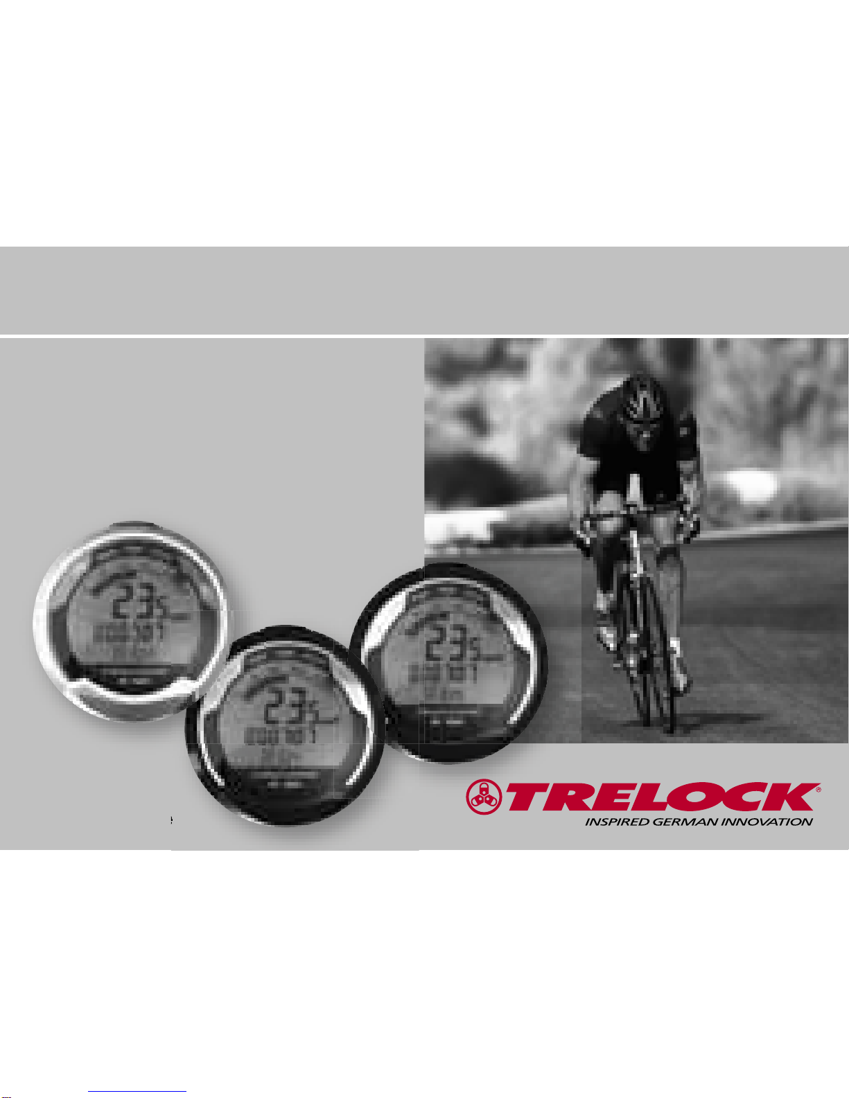
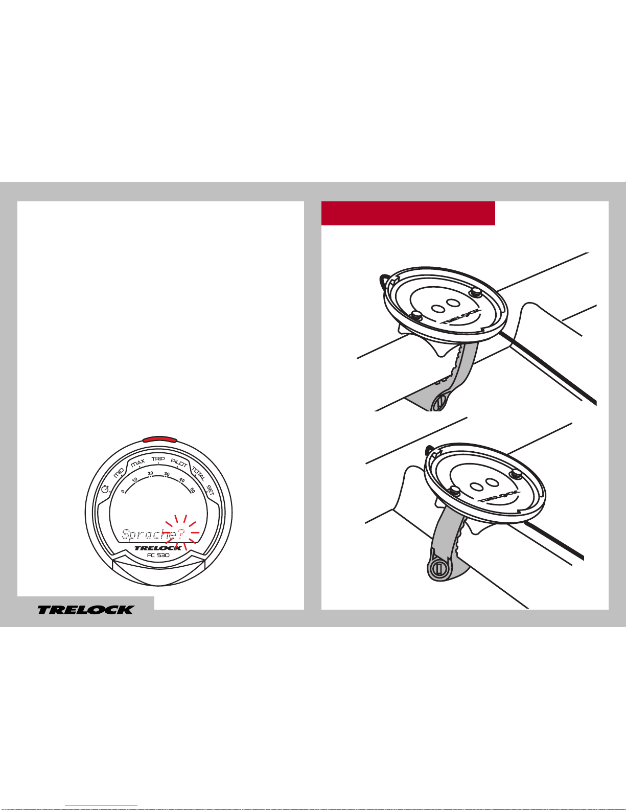
Trelock COCKPIT 2 FC 535 User manual

COCKPIT2FC 520/530/535
www.trelock.de
GB MANUAL

You have decided to purchase theTRELOCK
bike computer FC 520 (uni-base),
FC 530 (uni-base) or FC 535 (night-light
base) and, as such, your choice is an
excellent one. Your new bike computer is
easy and convenient to operate thanks to
the visual guidance system and large mono-
button typical of TRELOCK products. Please
read through this manual prior to your initial
usage of the computer.
36

Contents
1. Scope of supply 38
2. Activation of bike computer 39
3. Insertion of night-light base battery 39
4. Assembly/Installation 40
5. Display design and operating principle 45
6. General default settings 46
7. Main menus 55
8. Training 63
9. Additional information
and instructions 63
37

1. Scope of supply
1.1 FC 520, 530 1.2 FC 535
4x 4x
2x
38

3. Insertion of night-light base battery
Lithium Battery CR2032
When supplied to the customer, the
battery has already been inserted into the
bike computer. In order to activate the
computer, the red plastic flag must first be
removed. Turn the battery compartment
cap on the bottom of the computer in an
anti-clockwise direction and pull the flag
out. Then turn the cap firmly back in place.
2. Activation of bike computer
The display for your bike computer is fed
via a battery in the night-light base. In or-
der to insert this battery, use a coin to turn
the battery compartment cap in an anti-
clockwise direction and insert the battery
with the + sign pointing upwards (see fig.).
Then turn the cap firmly back in place.
3.1 FC 535
39

4. Assembly/Installation
By activating the computer, you automati-
cally access the “General Settings” in the
“Set” (SET) menu. How you can change
the general settings is described under
6.1. Should you wish to make changes to
the general settings at a later date, you
can access the “Set” (SET) menu by pres-
sing the MODE button for the appropriate
number of times and then pressing and
holding the SET and MODE buttons for
approx. 3 sec.
3.2 Information on initial operation 4.1 Assembly/Installation
of handlebar bracket
40

4.2 FC 520, 530
41

4.3 FC 535
42

4.4 Assembly/Installation
of sensor
43

4.5 Assembly/Installation of magnet
4444

5. Display design and operating principle
SET button
Analogue speedometer
display
Display line 1
Display line 2
Display line 3
Visual guidance
system
Change battery
MODE button
4545

6.1 Selection of language
Once the computer has been activated,
you automatically access the “Language?”
menu. By pressing the SET button, you
access the language selection option. Use
the MODE button to choose one of the eight
languages shown (German, English, French,
Dutch, Spanish, Italian, Russian or Polish)
and confirm your choice via the SET button.
6. General default settings
46

47

Dimensions
Dimensions
unit speed unit speed
set bike
6.2 Choice between km/h
and m/h
In the “Dimensions?” menu, “km/h”
is pre-set as the standard unit. If
you wish to accept this default
setting, press the MODE button.
To change it to “m/h”, press the
SET button. Then use the MODE
button to choose between “m/h”
and “km/h” in the “Unit Speed”
window. Confirm your choice via
the SET button.
48

6.3 Setting(s) of wheel size(s) (not
applicable to FC 520)
You can use your bike computer on two
bikes, even if their wheel sizes are diffe-
rent. To this end, you need a dedicated
transmitter/bracket unit (Art. ZF 405 for
FC 530 or ZF 409 for FC 535) and a spoke
magnet (ZF 50, accessory, not supplied as
standard) for each bike. In order to make
the settings for Bike 1 and Bike 2 in the
“Set Bike” window, press the SET button.
Use the MODE button to select “Bike 1”
or “Bike 2”. Confirm your choice via the
SET button.
set bike
bike 1
49

Setting(s) of wheel size(s) (wheel
circumference)
Under “Wheel Size 1” or “Wheel Size
2” (only for FC 530, 535), you should
now enter the wheel circumference
of your bike. This can be seen from
the wheel size data shown on the
side of your tyre. Please consult
the table shown on P. 17 for the
appropriate 4-digit number.
Next press the MODE button until
such time as the appropriate digit
appears, then use the SET button
to move to the next digit. Once you
have confirmed the final digit, you
automatically re-access the “Set
Wheel” window. Should you wish
to make settings for a second bike,
press the SET button, otherwise
move to the “Clock” window by
pressing the MODE button.
Wheel size (mm) =
2 x r (mm) x 3,14
1 inch = 25,4 mm
wheel size 1 wheel size 1
50

Wheel Size (WS) Chart (wheel sizes / wheel circumference)
ETRTO WS mm
47–305 16x1.75x2 1272
47–406 20x1.75x2 1590
50–406 20/2.00 1593
60–406 20/2.35 1665
37–540 24x1 3/8 A 1948
47–507 24x1.75x2 1907
50–507 24/2.00 1910
40–559 26x1.5 2026
44–559 26x1.6 2051
47–559 26x1.75x2 2074
50–559 26x1.9 2089
54–559 26x2.00 2114
57–559 26x2.125 2133
37–590 26x1 3/8 2105
20–571 26x3/4 1954
ETRTO WS mm
60–559 26/2.35 2146
32–630 27x1 1/4 2199
40–622 28x1.5 2224
47–622 28x1.75 2268
40–635 28x1 1/2 2265
37–622 28x1 3/8x1 5/8 2205
18–622 700x18C 2102
23–622 700x23C 2133
25–622 700x25C 2146
28–622 700x28C 2149
32–622 700x32C 2174
37–622 700x35C 2205
40–622 700x40C 2224
50–622 28/2.00 2284
60–622 28/2.35 2340
51

Clock
Clock
Clock
Clock?
Clock
6.4 Setting the current time
If you wish to change the time, press
the SET button. One after another,
hours, minutes and seconds (start
automatically after confirmation of
minutes) can be changed via the
MODE button. Use the SET button
to confirm your entries and to move
to the next digit.
52

6.5 Entering and changing the PIN anti-theft protection
Use a PIN to protect your bike computer from unauthorised
access. Activation of the bike computer is then only possible
if the correct pin is input. Once the time has been set, you
automatically access the “Change PIN?” window. Here you can
enter your own PIN and, if necessary, subsequently change it. If
you don’t wish to use a PIN, press the MODE button. Otherwise,
after pressing the SET button, you will be asked to enter the
old PIN (default setting is “0000“). To this end, press the MODE
button until such time as the appropriate digit appears and
then use the SET button to move to the next digit. PIN input is
monitored. Should the PIN have been entered incorrectly, the
message “Wrong PIN” appears for approx. 3 seconds and you
will be asked to re-enter the PIN. If the PIN is correct, input a
new PIN of your choice as described above. Once the last digit
has been confirmed via the SET button, PIN entry must be re-
peated. Should the repeat PIN entry be incorrect, you will return
automatically to the “Change PIN?” window. Note down your
personal PIN on Page 31 so that it is readily available if required!
change PIN?
enter PIN
53

PIN-Time PIN-Timeenter PIN
PIN-Time new?
6.6 Entering and changing the PIN time
If the bike computer is in Sleep mode and is not ‘awakened’ for a
set time, it has to be re-activated by entering your PIN. The period
concerned (PIN Time) can be (re)set in the “Set PIN Time” window
– after you have pressed the SET button, you will be asked to
enter your PIN. After correct PIN input, you automatically access
“PIN Time” where you can enter the time of your choice up to max.
240 minutes. If you wish to dispense with the securing of your bike
computer via a PIN, then set the PIN time to “000”.
54
Table of contents
Other Trelock Bicycle Accessories manuals

Trelock
Trelock COCKPIT2 FC 525 User manual

Trelock
Trelock COCKPIT2 FC 525 User manual

Trelock
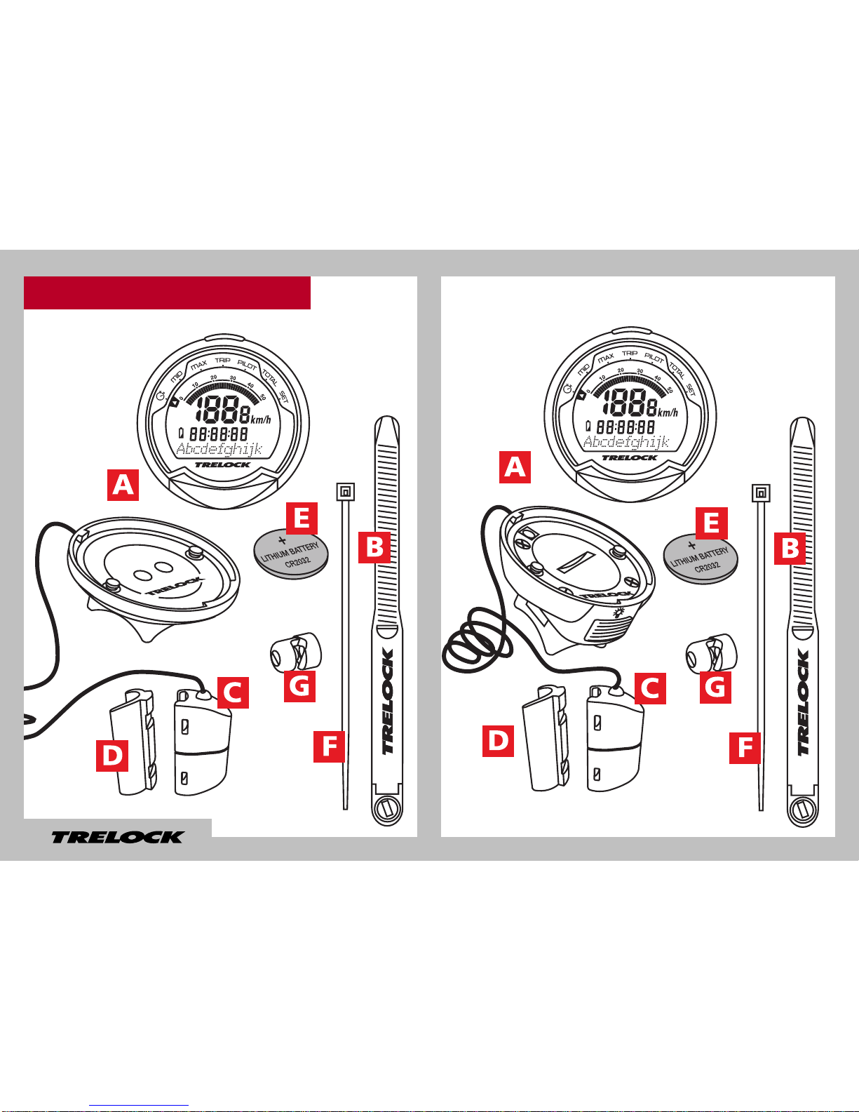
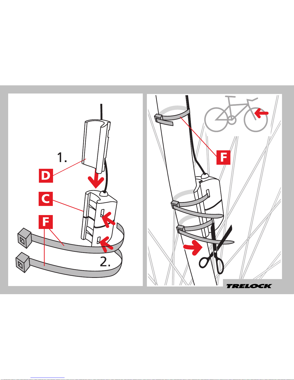
Trelock FC 510 Manual

Trelock
Trelock LIGHTHAMMER 40 USB User manual

Trelock
Trelock Bike-i duo LS 885 User manual

Trelock
Trelock LIGHTHAMMER 80 USB User manual

Trelock
Trelock BIKE & BODY BB 2000 User manual

Trelock
Trelock Vision LS 760 I-GO User manual

Trelock
Trelock BIKE & BODY Series User manual

Trelock
Trelock FS 200 Code User manual