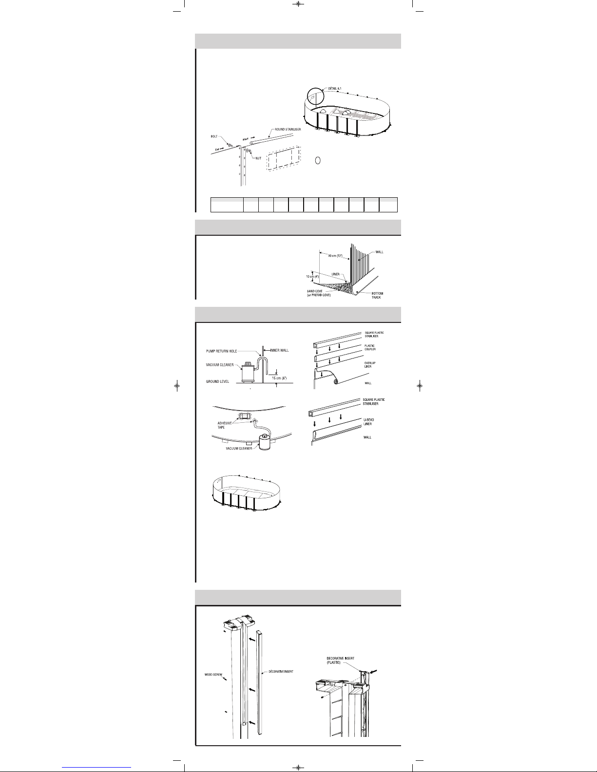
Before pulling the liner up against the wall, insert a vacuum
cleaner hose down into the pump return hole to approximately
15 cm (6") from the ground.
Maintain the hose in place with adhesive tape. Don't forget to
block the skimmer hole with adhesive tape to prevent air from
leaking in.
Place the unfolded liner in the center of the pool area at right
angles with the skimmer hole. Make sure you wear light, flat-
soled shoes to walk on the sand as the slightest heel mark could
be visible once the pool is filled.
Carefully unfold the liner, bringing the bottom-sidewall seam
close to the wall base. Make sure that the side with the protrud-
ing seams faces downward or that the patterned side faces
upward.
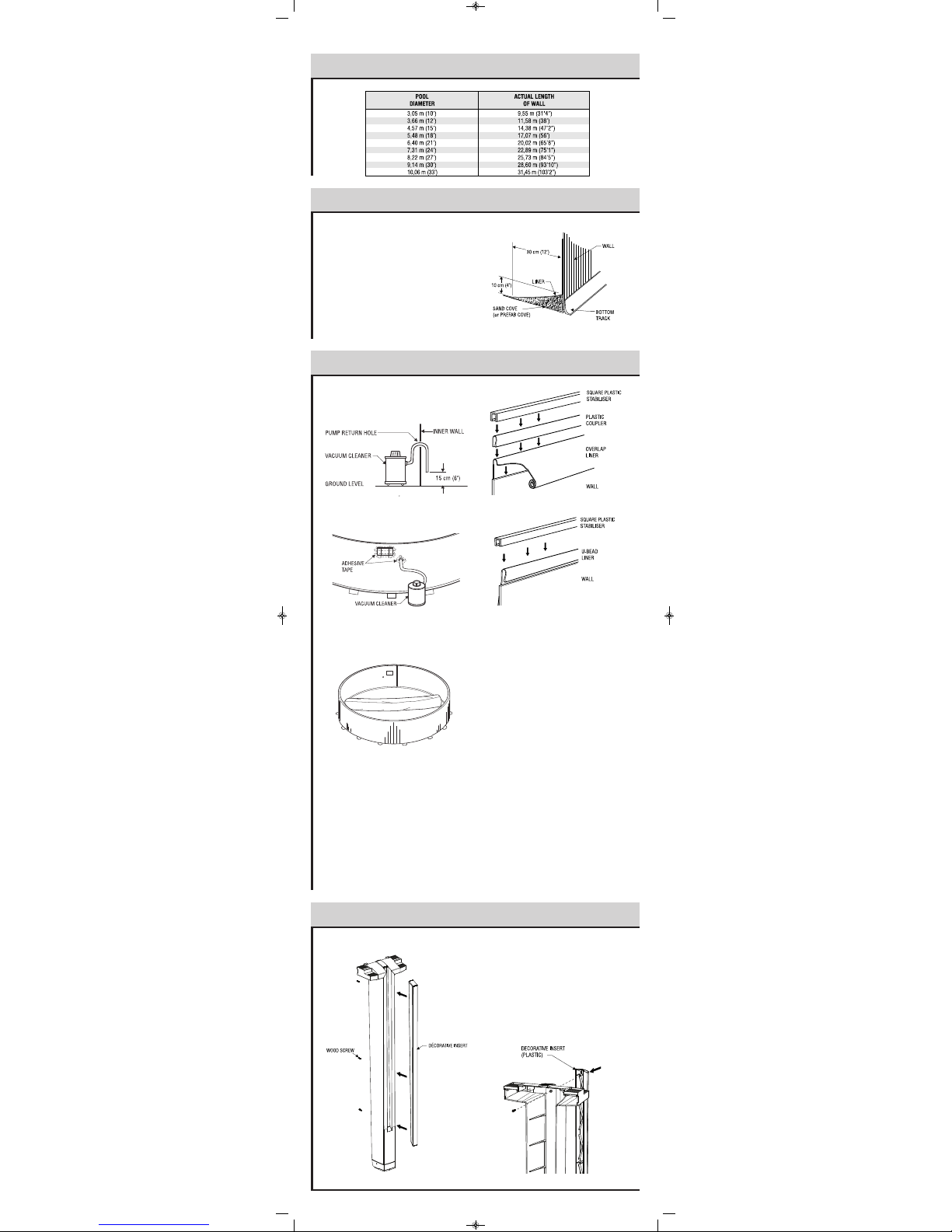
Install the plastic coupler on the wall (optionnal). ift up a sec-
tion of the liner over the top of the wall leaving a 10 cm to 15 cm
(4" to 6") fringe outside the wall. Secure the liner with a plastic
coupler then install the joiner plates on top of each upright.
At this point, the liner may be too tight, making it difficult to
drape the overlap or, on the contrary, too loose. In such cases,
you will have to redistribute the tension in the liner by remo-ving
some of the couplers and readjusting the liner.
Installation detail of the u-bead liner.
Hang the liner on the top of the wall and install the square sta-
biliser to secure.
Start the vacuum cleaner to allow the liner to adhere to the wall
and check for excess tension at the bottom or for wrinkles.
Adjust the liner by removing couplers if needed, to lift or lower it
in order to ensure a perfect fit.
Fill the pool up to the base of the wall before stopping and
removing the vacuum cleaner.
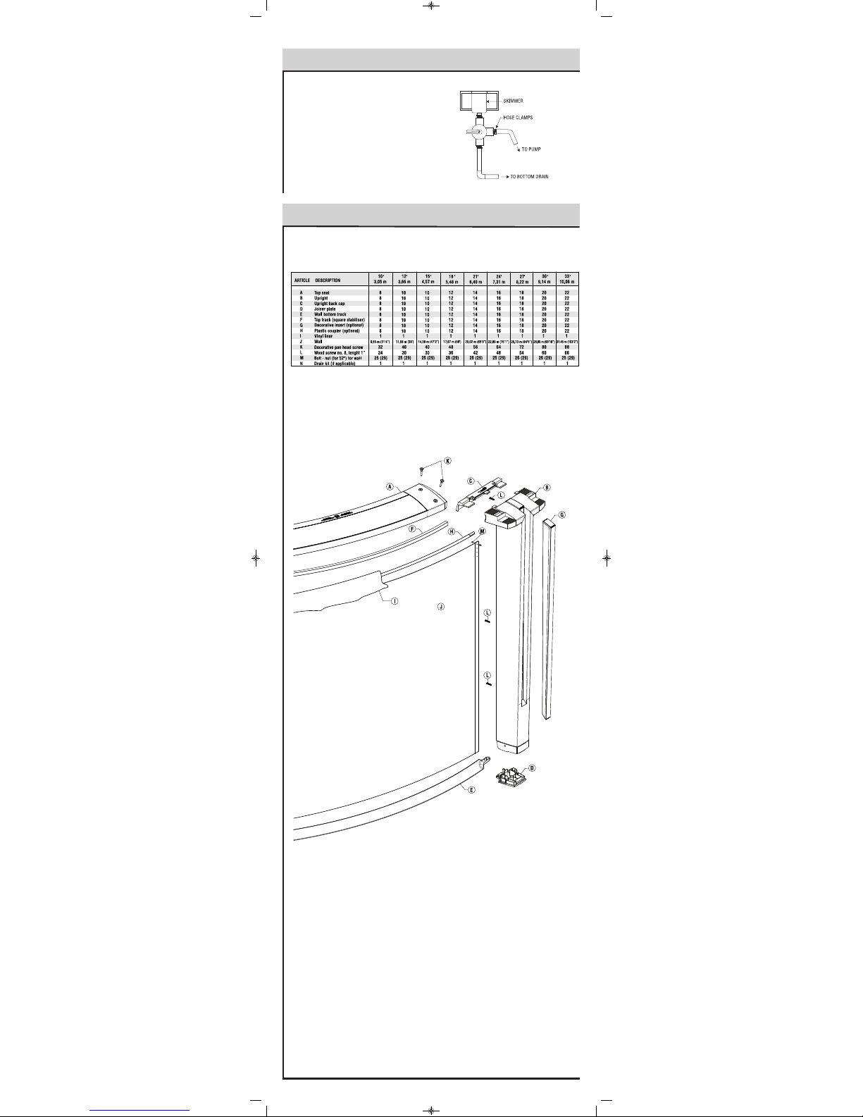
PUMP RETURN FITTING
After you remove the vacuum cleaner, you may install the return
fitting. Place the return fitting ring against the liner and adjust it
so that it is perfectly aligned with the hole in the wall.
When the ring is properly positioned and secured, cut the liner in
the middle of the ring. Insert the return fitting from the inside,
placing the first gasket between the return fitting and the liner
and the second between the wall and the liner. Then tighten the
outside ring with large pliers, taking care not to crease the liner.
BOTTOM DRAIN (optional)
Find the holes through the middle of the liner and screw the ring
and gasket in against the liner before cutting the liner in the mid-
dle of the ring, then screw on the drain cover.
!$
10
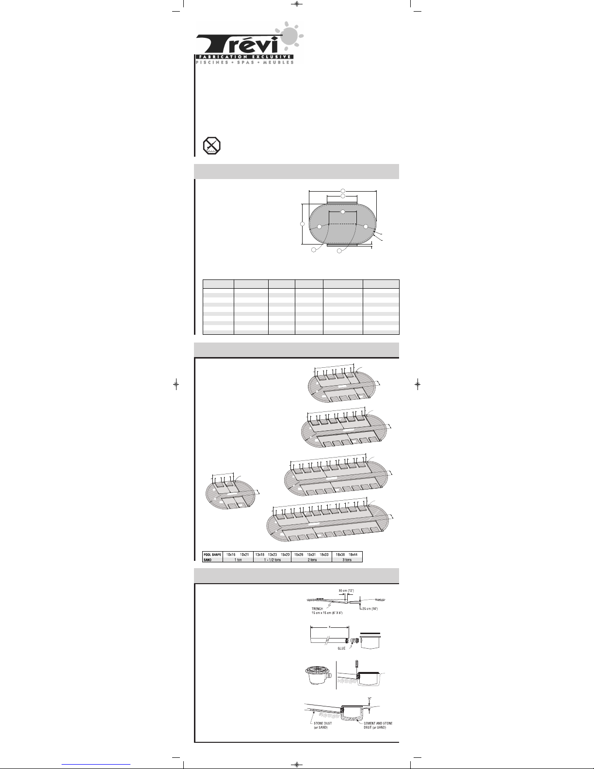
You can now spread approximately 10 cm (4") of compacting
sand all around the inside base of the wall in order to protect the
liner from the cutting edges of the bottom wall tracks and the
stone dust (if applicable). Or install a prefabricated cove, if avail-
able.
AND BA E FINI HING
evel finishing sand one last time. Make sure that any sharp
stones, debris or roots have been removed from the surface. For
better protection, spray sand with water and pack it once more
until the base is nicely even.
9
"(/.3,.4*)
8
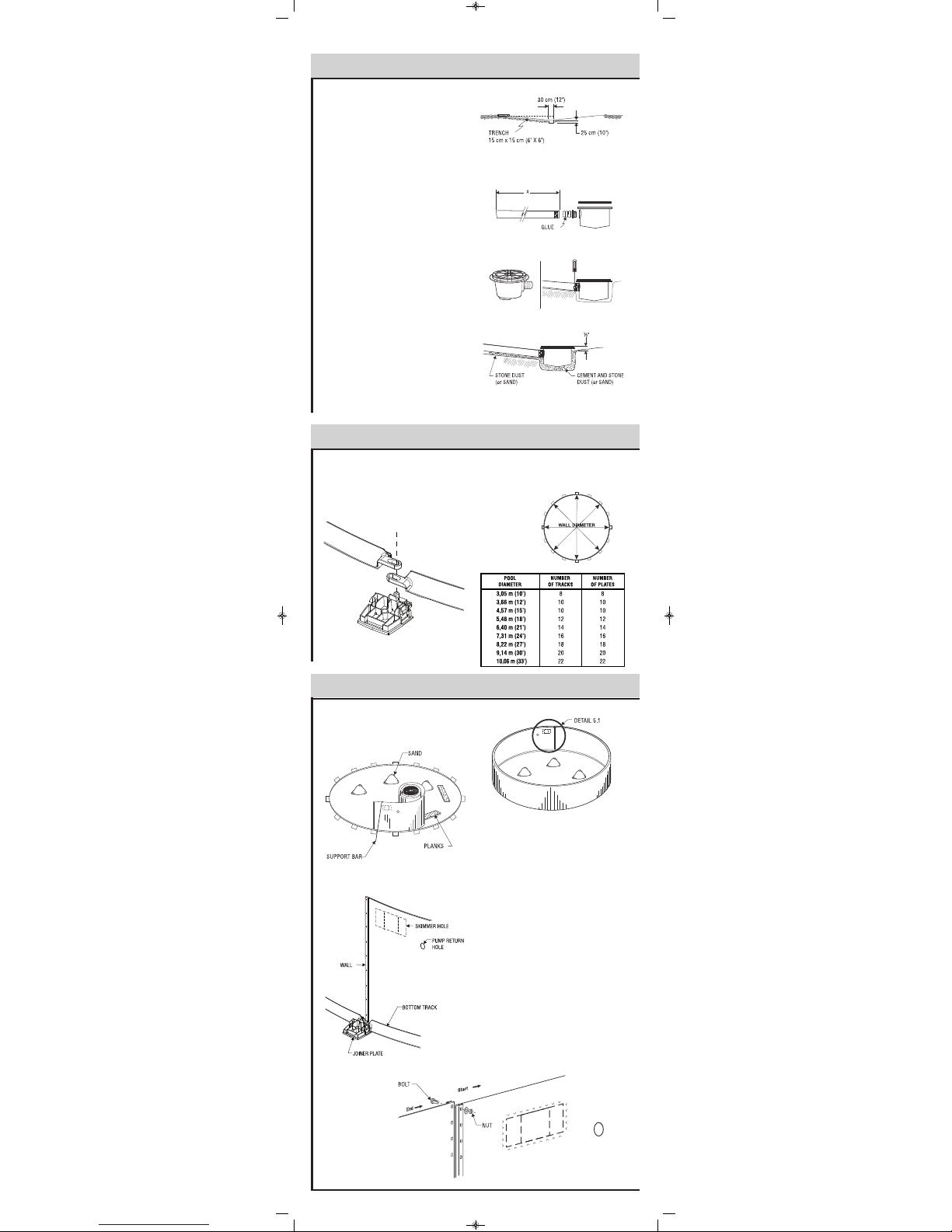
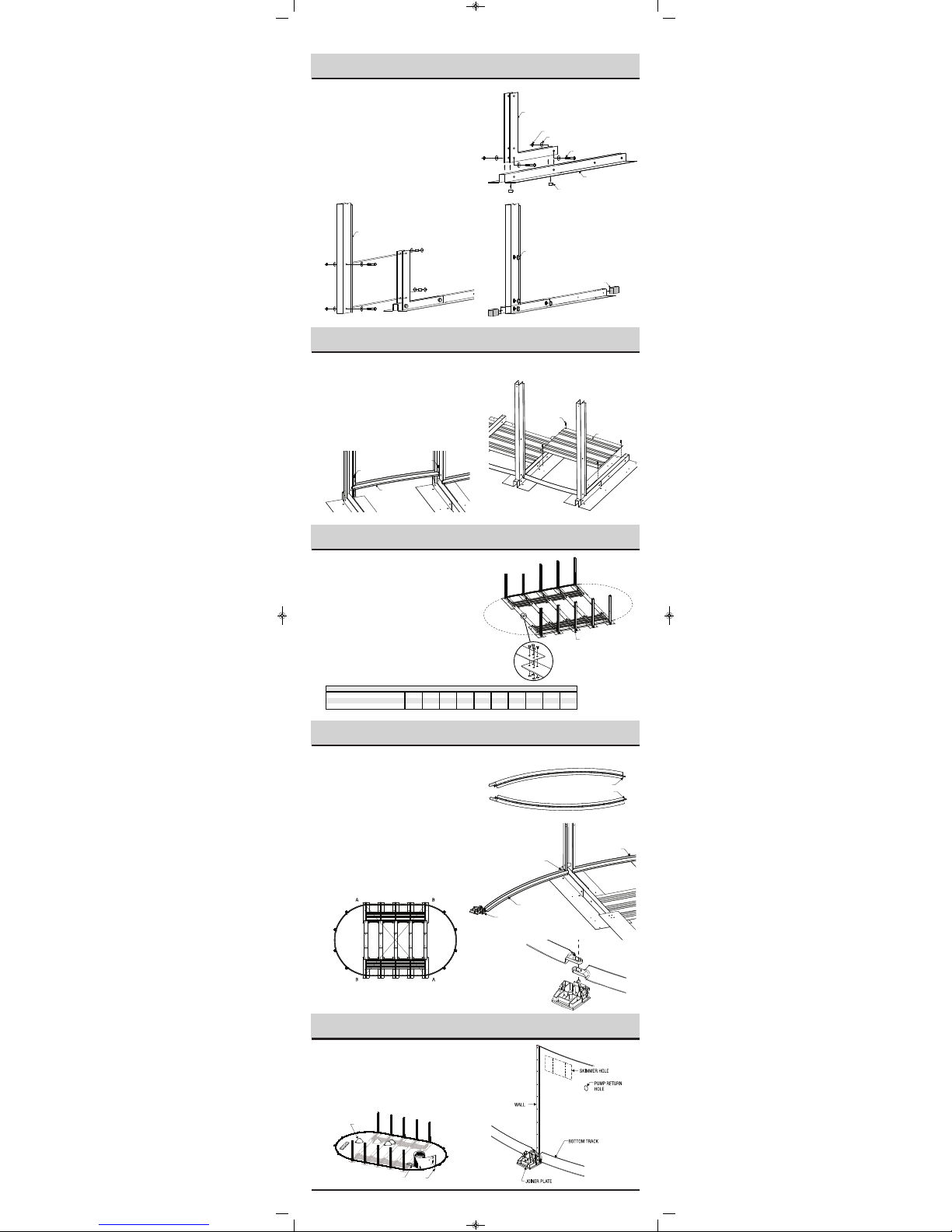
Begin inserting the wall into the bottom wall tracks in the middle
of a joiner plate. At first, the wall is kept in place with one or two
support bars (or extra persons). One person uncoils the wall on
a beam or a plank, while a second person inserts it in the bot-
tom wall tracks. Do not uncoil more than 3 m (10') of wall before
you install a support bar to reinforce the structure.
Once the wall is completely uncoiled, you may find that it is too
long or that both ends do not meet by a few centimetres. If such
is the case, you must gently push the wall in or out. If this does
not work, roll up the wall again, realign the grooves and uncoil
the wall again. If the spread is too wide, measure the wall and
check it against the following chart.
When you prepare to join the ends of the wall, make sure the end
that is reinforced by the fold is inside the circle, facing the liner
and that the other end faces outward (Illustration 8.1).
When the wall joint is secured, install the round stabilisers on top
of it.
IMPORTANT: Due to the enormous
pressure exerted by the water on the
steel wall, it is absolutely essential that
all the bolts are screwed in tigh-tly and
no hole is left open. All bolt heads
must be inside with washer and nut
outside. Cover all bolt heads with
heavy fabric tape.