Tridonic modularDIM SC User manual

Control module for PCA/TE one4all/PCD
For DIN rail
modularDIM BASIC
Control module with 3 channels/single, twin push to make switches/
presence detector/modularDIM power supply
type modularDIM BASIC
article number 86454539
electrical supply voltage V 120–277
frequency Hz 50/60
max. load VA < 10
input push to make switches * – single/twin
PIR sensor – 3
control line iX (intelligent extension) – 1
output digital DSI control signal – 3
signal – digital/serial
voltage V 12 ±10 %
data rate Bd 1 200
max. number of PCA/TE one4all/PCD 100
max. cable length m 250
iX (intelligent extension) – 1
temperature permitted ambient temperature °C 0 →+50
The modularDIM BASIC control module is the
basis of the modularDIM product range. The three
output channels can be controlled individually or
together. Simple installation since no programming
is required.
Parallel connection of several switches enables
user-friendly dimming and “ON/OFF” switching
from several points. The modularDIM BASIC
contains the central power supply for all modular-
DIM components.
5-year guarantee
luxCONTROL modularDIM
Packaging carton:
10 pc(s).
* Switch inputs are safety low voltage (SELV).
Any standard push to make switch may be used
Data sheet 08/14-CO061-3 We reserve the right to make technical changes without prior notice.
Glow-wire test
according to EN 60598-1 passed.

Control module for PCA/TE one4all/PCD
For DIN rail
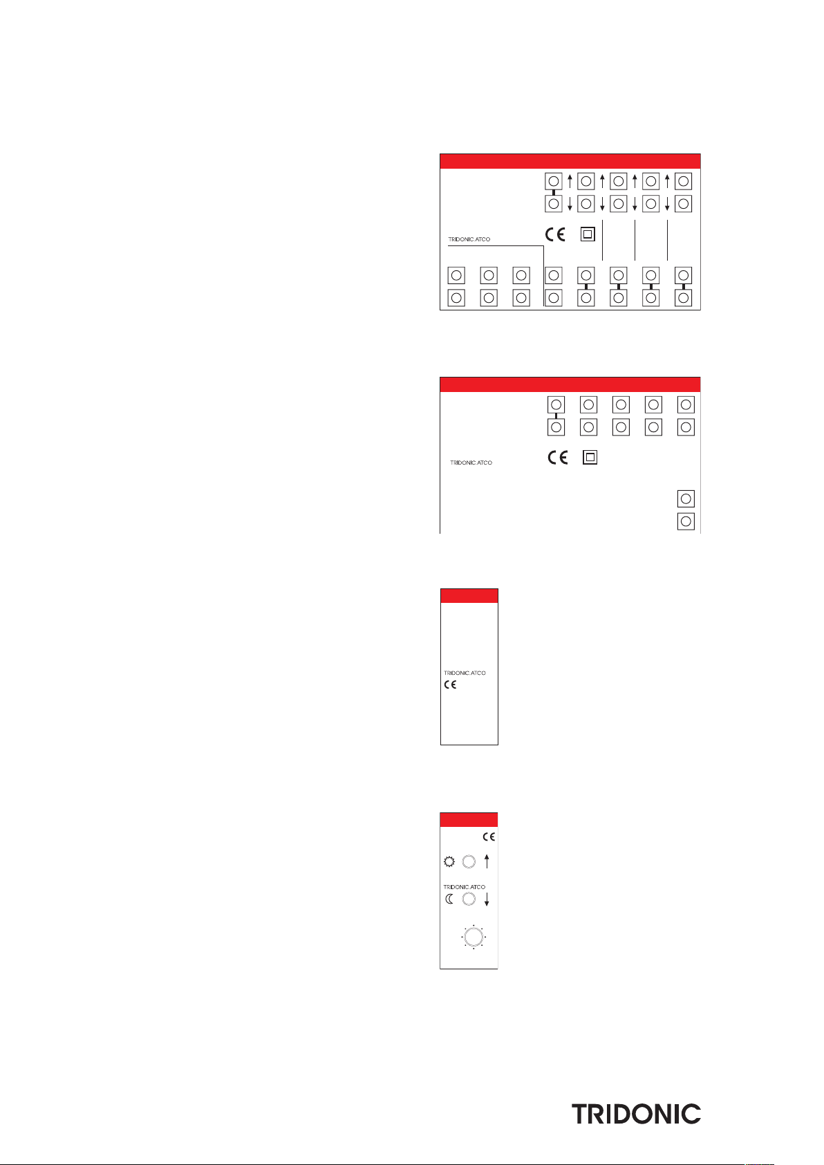
modularDIM SC
Scene module for independent control of 4 light scenes
type modularDIM SC
article number 86454545
supply – – via iX (intelligent extension)
input 4 push to make switches * – single
output control line iX (intelligent extension) – 1
status LED’s (8 V) – 4
temperature permitted ambient temperature °C 0 →+50
Expansion module for modularDIM systems to
control scenes. Enables the recall and program-
ming of four light scenes via the modularDIM
BASIC. The switch inputs are SELV and any push
to make switches can be used.
5-year guarantee
luxCONTROL modularDIM
* Switch inputs are safety low voltage (SELV).
Any standard push to make switch may be used
Packaging carton:
1 pc(s).
2Data sheet 08/14-CO061-3 We reserve the right to make technical changes without prior notice.
Glow-wire test
according to EN 60598-1 passed.

Control module for PCA/TE one4all/PCD
For DIN rail
modularDIM DM
Control with daylight sensor/3 channels
type modularDIM DM
article number 86454564
supply – – via iX (intelligent extension)
input daylight sensor – 1
switch manual/automatic – 1
output control line iX (intelligent extension) – 1
temperature permitted ambient temperature °C 0 →+50
Expansion module for daylight linked control of the
modularDIM BASIC module. The daylight informa-
tion will be passed on from the modularDIM DM to
the basic module to control up to three application-
specific luminaire groups. Simple programming of
each independent luminaire group.
5-year guarantee
accessories sensor DAYLIGHT
article number 86454586
The modularDIM system includes an attractive and
solid ceiling mounted sensor for the detection of
sky brightness. Its sensing aperture is aligned in
the direction of the daylight.
5-year guarantee
Packaging:
single packaged
box of 10
luxCONTROL modularDIM
Packaging carton:
30 pc(s).
3
Data sheet 08/14-CO061-3 We reserve the right to make technical changes without prior notice.
60
30°
Ø 80
2415
5
Ø 80
Glow-wire test
according to EN 60598-1 passed.

4Data sheet 08/14-CO061-3 We reserve the right to make technical changes without prior notice.
luxCONTROL modularDIM
Control module for PCA/TE one4all/PCD
For DIN rail
modularDIM LC
“Line Converter” for the integration of mains rated “presence detection” units/sensors
The well known modularDIM system will be
extended by the new designed modularDIM LC
which provides the opportunity to integrate
common, commercial of the shelf mains rated
“presence detection (PD) units/sensors” (converts
main rated signals into potential free signals based
on the galvanic isolation). The modularDIM LC is
designed as “to build in unit” for the integration
into a switch cabinet. This unit is easy to install
Packaging carton:
30 pc(s).
type modularDIM LC
article number 86457888
voltage V 220–240
frequency Hz 50/60
galvanic isolation spec. – 4000 V 2 min.; 6 mm (SELV)
max. output voltage V 30
permitted ambient temperature °C 0 →+50
and to commission because there is no
programming effort.
Therefore this important feature of the modular-
DIM LC gives now the opportunity to
combine the modularDIM system with the
common, commercial of the shelf main rated
“presence detection (PD) units/sensors”.
5-year guarantee
outputs are safety low voltage (SELV).
Glow-wire test
according to EN 60598-1 passed.
modularDIM BASIC
The modularDIM BASIC module is at the heart of the modularDIM concept.
It has three output channels which can individually drive up to 100 DSI
devices (PCA, TE one4all, PCD) and provides power to the extension modules
via the iX interface. DSI devices connected to each channel can be dimmed
or switched via the DSI signal as independent channels or combined as one
group. In addition the modularDIM BASIC has three PIR inputs to connect
standard presence detectors with potential free contacts. Each channel can
be switched independantly. One presence detector can be linked to all three
channels via a bridge to the other PD inputs thereby allowing all three
channels to be switched as one.
modularDIM SC
The modularDIM SC is an extension module powered directly by the modu-
larDIM BASIC module. It has been designed to allow the user to recall four
different light scenes. A short push of the momentary switch recalls a light
scene. To store a light scene you must initially set the light levels via the
modularDIM BASIC module. A long push (> 10 s) to one of the modularDIM
SC momentary switches stores the new light scene. Confirmation that the
scene has been stored will be indicated by the luminaires connected to the
modularDIM BASIC module dimming up and down.
modularDIM LC
The well known modularDIM system will be extended by the new designed
modularDIM LC which provides the opportunity to integrate common,
commercial of the shelf mains rated “presence detection (PD) units/sensors”
(converts main rated signals into potential free signals based on the galvanic
isolation). The modularDIM LC is designed as “to build in unit” for the
integration into a switch cabinet. This unit is easy to install and to
commission because there is no programming effort.
Therefore this important feature of the modularDIM LC gives now the
opportunity to combine the modularDIM system with the common,
commercial of the shelf main rated “presence detection (PD) units/sensors”.
* PD 1 – PD 3 potential free in order to the com-contact (because of the
galvanic isolation)
modularDIM DM
The modularDIM DM is an extension module powered directly by the modu-
larDIM BASIC module. It is designed to provide daylight linked control of
the artificial lighting in a room. The daylight value if measured by a daylight
sensor that is connected directly to the modularDIM DM module. Daylight
control is across a dimming range of 0 % to 100 %, with each
channel being programmed with its own dimming characteristic. Channels
can be controlled independently or as combinations of channels. The
automatic daylight linked control can be disabled via an external switch
(switching contact open →daylight function active / switching contact
closed →daylight function inactive).
Technical description
The modularDIM lighting control system consists of three modules. The modularDIM BASIC module, which acts as a group controller and power supply to
the two remaining modules. The modularDIM SC module for recalling light scenes and the modularDIM DM daylight linked module.
iX
com All
LN
com
D2
D1
D2
D1
D2
D1
X2
X1
PD
G 1 G 2G 3
DSI out
G 1 G 2 G 3
120-277V
max. 100 PCA/TEL/PHD
Ta: 0-50°C
PD PD
86454539
luxCONTROL
modularDIM BASIC
50/60Hz
iX
Active Group
Man./Auto
12
3
1+2
1+3
2+3
all
S2
S1
DAYLIGHT
Sensor
modularDIM DM
86454564
luxCONTROL
S1 S2
Sx: push to make switch scene
Lx: scene indication output
S3 S4
L1 L2 L3 L4
iX
X2
X1
com
86454545
luxCONTROL
modularDIM SC
use only in combination with
luxCONTROL
modularDIM BASIC
Ta: 0-50°C
5
Data sheet 08/14-CO061-3 We reserve the right to make technical changes without prior notice.
PD3
com
PD1
PD2
L3
N
L1
L2
modularDIM LC
86457888
Line Converter
PD out for
modularDIM BASIC
230V 50/60Hz
PD' switched line
luxCONTROL
*
**
*

Programming the daylight linked function
The dimming curve for daylight management is set via the modularDIM DM
module or via the light sensor itself. Two values are stored, appropriate to
the external lighting conditions, Twilight and Daylight set points.
Two switches on the modularDIM DM module represent these positions.
Light levels for the programming of the daylight set points are set via the
modularDIM BASIC module.
Interior
lighting Control characteristics
Row I
Row II
Row III
Day
available
daylight
Night
100 %
0 %
Twilight system points
(System points A)
Daytime system points
(System points B)
Programming of day time system set point
The settings should be programmed under sufficient daylight conditions,
preferably, when the row of luminaires nearest the window, are dimmed
to their lowest possible setting to achieve the designed light level.
1. Set desired light level for each row of luminaires I – III via
modularDIM BASIC.
2. Select respective channels via selector switch on
modularDIM DM module.
3. Save the daytime system point by pressing (> 5 s) the Sun key (Sys B)
by means of e.g. a ball-point.
4. Storage of the system point is acknowledged by the flashing of the
lighting source.
5. For programming further channels, repeat steps 1–4.
6. Select the channel you wish to control via daylight management by
selecting the appropriate channel or combinations of channels using
the selector switch on the modularDIM DM module.
0 % 25 % 50 %
500 LUX
Artificial light
Daylight
Day
IIIIII
Programming of twilight set points
The settings should be programmed under twilight conditions, preferably,
when hardly any daylight is present. Alternatively, the settings may be
programmed during the day, with the daylight-sensor covered.
1. Set desired light level for each row of luminaires I – II via
modularDIM BASIC.
2. Select respective channels via selector switch on
modularDIM DM module.
3. Save the twilight system point by pressing (> 5 s) the Moon key (Sys A)
by means of e.g. a ball-point.
4. Storage of the system point is acknowledged by the flashing of the
lighting source.
5. For programming further channels, repeat steps 1–4.
6. Select the channel you wish to control via daylight management
by selecting the appropriate channel or combinations of channels
using the selector switch on the modularDIM DM module.
I
II III
80 % 90 % 100 %
500 LUX
Artificial light
Daylight
Twilight
6Data sheet 08/14-CO061-3 We reserve the right to make technical changes without prior notice.

As many momentary switches as required
can be wired in parallel.
*
L
N
modularDIM Basic
****
L N COM ALL I II III
D1 D2 D1 D2 D1 D2 X1 X2 COM PD I PD II PD III
groups
I II III iX
COM S1 L1 S2 L2 S3 L3 S4 L4
scenes
Sx ... momentary switches
Lx ... scene indication
modularDIM SC
iX
X1 X2
modularDIM LC
Sensor DAYLIGHT
**
PD1 PD2 PD3 com
PD PD PD
L1 L2 L3 N
N L L' N L L' N L L'
ALL I II III
iX ... intelligent extension
DAYLIGHT function
ON/OFF
2PCA
6D1 / DA
D2 / DA
3
4
7
max. 100 PCA/TE one4all/PCD/LCA
III
max. 100 PCA/TE one4all/PCD/LCA
II
max. 100 PCA/TE one4all/PCD/LCA
I
The light sensor „Sensor DAYLIGHT“ is to be installed with free view direction window (consider mounting instruction).
max. wire lengths:
• DSI: max. 250 m
• Momentary switch: max. 100 m
• Scene indication: max. 100 m
• iX: max. 10 m
• Sensor DAYLIGHT: max. 100 m
• DAYLIGHT function ON/OFF: max. 100 m
• PD: max. 100 m
L N
**
D1 / DA
D2 / DA
L
N
LCA
D1 / DA
D2 / DA
L
N
PCD
2PCA
6D1 / DA
D2 / DA
3
4
7
D1 / DA
D2 / DA
L
N
LCA
D1 / DA
D2 / DA
L
N
PCD
2PCA
6D1 / DA
D2 / DA
3
4
7
D1 / DA
D2 / DA
L
N
TE
one4all
D1 / DA
D2 / DA
L
N
PCD
modularDIM DM
channel
selector
iX X2
AUTO
S1
S2
S1
S2
X1
MAN
Installation instructions
• Toenableseveraloperatingpointstobeused,severalkeysorswitchesareconnectedinparallel.
• Themaximumoperatinglengthofallkeys,aswellasthelightsensor,maynotbemorethanamax.lengthof100m.
• TheDSIsignalistransmittedbyafunctionalextralowvoltage(notsafetyextralowvoltage).Useinstallationmaterialthatisdesignedformains
voltage installations (230 V 50 Hz) therefore.
• Theinputsandoutputsforthekeys,daylightsensorandfortheiXinterfacemeettherequirementsforsafetylowvoltage.
Important note: if one of the safety low voltage inputs/outputs is not wired in accordance with the relevant requirements, the other inputs
outputs should also be wired with installation material designed for mains voltage installation (230 V 50 Hz).
• Thekeyinputscomplywiththerequirementsofsafetylowvoltages.Anykindofkeycanbeused.
Data sheet 08/14-CO061-3 We reserve the right to make technical changes without prior notice.
This manual suits for next models
3
Table of contents
Other Tridonic Control Unit manuals


