Trillium SARASIN-RSBD STARFLOW V Series Instruction manual

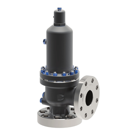
V SERIES (STARFLOW VTM )
Installation, Operation,
Maintenance Manual

CONTENT
1 SAFETY SIGN AND LABELS ................................................................................................................................................. 3
2 SAFETY INSTRUCTIONS....................................................................................................................................................... 4
3 SAFETY PRECAUTIONS........................................................................................................................................................5
4 WARRANTY INFORMATION.................................................................................................................................................. 6
5 TERMINOLOGY....................................................................................................................................................................... 7
6 GENERAL ADVICE.................................................................................................................................................................. 8
6.1 RESPONSIBILITIES......................................................................................................................................................................... 8
6.2 IDENTIFICATION PLATE..................................................................................................................................................................8
6.3 SPRING ........................................................................................................................................................................................ 9
6.4 STORAGE ......................................................................................................................................................................................9
6.5 HANDLING ....................................................................................................................................................................................10
7 STARFLOWTM BASICS.......................................................................................................................................................... 11
7.1 DESCRIPTION ............................................................................................................................................................................... 11
7.2 FEATURES AND NOMENCLATURES ................................................................................................................................................. 12
8 INSTALLATION......................................................................................................................................................................16
8.1 GENERAL .....................................................................................................................................................................................16
8.2 INLET PIPING ............................................................................................................................................................................... 16
8.3 OUTLET PIPING ............................................................................................................................................................................ 17
8.4 INSTALLATION ON THE PROTECTED EQUIPMENT ............................................................................................................................17
8.5 LEVER ORINTATION ......................................................................................................................................................................20
8.6 OUTDOOR INSTALLATION ..............................................................................................................................................................20
8.7 INDOOR INSTALLATION ................................................................................................................................................................. 20
9 MAINTENANCE.................................................................................................................................................................... 21
9.1 DISASSEMBLY OF THE STARFLOW V™.......................................................................................................................................... 22
9.2 INSPECTION OF THE STARFLOW V™........................................................................................................................................... 27
9.2.1 GENERAL RECOMMENDATIONS ....................................................................................................................................... 27
9.2.1 PART INSPECTION ......................................................................................................................................................... 27
9.3 RE-ASSEMBLY .........................................................................................................................................................................32
9.3.1 NOZZLE/GUIDE ASSEMBLY ............................................................................................................................................32
9.3.2 DISC/DISC HOLDER ASSEMBLY ....................................................................................................................................32
9.3.3 ADJUSTMENT OF THE LIFT ..........................................................................................................................................32
9.3.4 BODY PLATE AND SPINDLE ASSEMBLY ..........................................................................................................................34
9.3.5 ADJUSTEMENT OF OVERLAP RING ................................................................................................................................ 34
9.3.6 ADJUSTMENT OF THE LOWER ADJUSTING RING .............................................................................................................35
9.3.7 ADJUSTMENT OF THE UPPER ADJUSTING RING ............................................................................................................. 35
9.3.8 SPRING ASSEMBLY ..................................................................................................................................................... 36
9.3.9 CAP ASSEMBLY .......................................................................................................................................................... 36
10 TESTING............................................................................................................................................................................... 37
10.1 TEST GAG ............................................................................................................................................................................... 37
10.2 SET PRESSURE AND ADJUSTMENT OF RINGS ............................................................................................................................. 38
10.2.1 SET PRESSURE ADJUSTMEN ........................................................................................................................................ 39
10.2.2 BLOWDOWN ................................................................................................................................................................ 39
10.2.3 UPPER AND LOWER RINGS ADJUSTMENT ..................................................................................................................... 39
10.3 CALIBRATION CHECK WITH ONLINE TESTING DEVICE ................................................................................................................ 40
10.4 VALVE SEALING ..................................................................................................................................................................... 40
11 MAINTENANCE TOOLS....................................................................................................................................................... 40
12 TROUBLESHOOTINGS........................................................................................................................................................ 41
13 SPARE PARTS..................................................................................................................................................................... 42
14 DISMANTLING..................................................................................................................................................................... 42
15 GENUINE PARTS.................................................................................................................................................................. 43
16 CODIFICATION..................................................................................................................................................................... 44
1| www.trilliumflow.com
STARFLOW V™PRESSURE RELIEF VALVE
SARASIN-RSBD™

SAFETY SIGNS AND LABELS
Signs or labels are included throughout this document.
These signs or labels communicate the following messages:
•
•
•
•
The level of hazard seriousness
The nature of the hazard
The consequence of human or product interaction with the hazard
The instructions if necessary on how to avoid the hazard
The format is characterised by vertical panels. The panels include a signal word shown below which advises the
level of hazard seriousness
• DANGER
• WARNING
• CAUTION
• ATTENTION
DANGER
WARNING
CAUTION
ATTENTION
DANGER
Immediate danger which
WILL cause
serious personal injury
or death.
WARNING
Risk or dangerous
practice which
COULD cause
serious personal
injury or death.
CAUTION
Risk or dangerous
practice which
COULD cause
minor injuries.
ATTENTION
Risk or dangerous
practice which
COULD cause
damage to equipment.
Never face the outlet of a
valve when it is discharging
as this may result in serious
personal injury or death
Be aware of all site safety
procedures to prevent the risk
of serious injury or death.
Protect yourself by wearing
the necessary protective
equipment to prevent
possible injury.
Use the proper lifting
equipment to avoid personal
injury or damage to
equipment.
2| www.trilliumflow.com
STARFLOW V™PRESSURE RELIEF VALVE
SARASIN-RSBD™

2 SAFETY INSTRUCTIONS
WARNING
CAUTION
ATTENTION
Be aware of all site safety
procedures to prevent the risk
of serious injury or death.
Protect yourself by wearing
the necessary protective
equipment to prevent
possible injury.
Use the proper lifting
equipment to avoid personal
injury or damage to
equipment.
•In order that the product may work as expected, ensure that it has been correctly installed, it is being correctly used
and it is correctly maintained and serviced.
• This document describes the main procedures which are necessary to satisfy to the essential safety requirements in
order to operate the product correctly and to comply with the International rules and regulations for the specified
pressure equipment.
• This document describes each essential step from the receipt of valves through the stages of installation, operation
and service. It is mandatory to ensure that anyone intervening with the product, directly or indirectly, is fully aware of
these steps. Pictograms are used to clearly advise of the potential dangers associated with the use of the product.
• Whilst this document is intended to be informative, it is important to understand that the safety messages provided
are not exhaustive. Trillium Flow TechnologiesTM cannot possibly be aware of, evaluate or
advise, all of the conceivable methods by which tasks might be performed, or of the possible hazardous
consequences of each of those methods.
Consequently, anyone who uses a procedure and/or tool, which is not recommended by Trillium Flow TechnologiesTM,
or deviates from Trillium Flow TechnologiesTM recommendations must be thoroughly satisfied that neither personal
safety nor equipment safety will be jeopardized by the method and/or tools which have been selected.
The installation, operation and maintenance of safety valves could be dangerous. During these activities personnel might be exposed
to direct or indirect injury risks from fluids which are at various high pressures and/or temperatures. Therefore, every precaution
should be taken to prevent injury to personnel during the performance of any procedure. Any person who uses a safety valve shall be
trained in all aspects of handling, installation, operation and service.
3|www.trilliumflow.com
STARFLOW V™PRESSURE RELIEF VALVE
SARASIN-RSBD™

3 SAFETY PRECAUTION
DANGER WARNING CAUTION
Never face the outlet of a
valve when it is discharging
as this may result in serious
personal injury or death
Never dismantle a valve in
line without making
absolutely sure there is no
remaining or residual
pressure
Protect yourself by wearing
the necessary protective
equipment to prevent
possible injury
•Never stand in front of the discharge side of a safety valve if the valve is operating or being tested.
•Always wear personal protective equipment (PPE): PPE should consist of but not be limited to ear protection, eye
protection, and the use of protective clothing (gloves, headgear, etc). Noise can be extremely high and can occur
suddenly. Steam and hot water can burn. Superheated steam is NOT visible.
•Always lower the operating pressure before making any adjustment to the valve. Always gag the valve before making
any ring setting adjustments.
•Before removing a valve for disassembly, ensure that there is no remaining pressure upstream the valve and that the
valve is isolated from the system pressure.
•Before performing each pop test on the safety valve, ensure that no personnel are close to the valve. The steam which
could escape during the operation could cause serious personal injury.
•When a lift test is performed using the lifting lever, be sure to use a rope or a chain whilst standing at a safe
distance away from the valve and any potential steam escapes.
•Valves under the operating pressure may relieve at any time. Never strike the body or tamper with the valve as such
practice could cause premature relief.
•Never modify or change the valves, especially when they are under pressure. It is essential that you inform Trillium Flow
TechnologiesTM in All instances if any machining of parts is to be considered. Deviation from critical dimensions
can adversely affect the performance of a safety valve.
A safety valve is a self-acting product. Always consider the potential dangers associated with the product and never minimise them.
Each plant or installation has its own safety rules. Be aware of them and follow them carefully.
4|www.trilliumflow.com
STARFLOW V™PRESSURE RELIEF VALVE
SARASIN-RSBD™

4 WARRANTY INFORMATION
Trillium Flow TechnologiesTM warrants that its products (including performance) and work will meet the specifications of
the customer’s Purchase Order. If any issue arises whilst operating the product, the customer should inform Trillium Flow
TechnologiesTM as quickly as possible. A return to the original plant should then be considered in order for Trillium Flow
TechnologiesTM to inspect the product.
Trillium Flow TechnologiesTM cannot be held responsible for any incorrect sizing and selection of a valve if the original
specification supplied by the customer was incomplete or inaccurate.
Trillium Flow TechnologiesTM does not authorise any third parties (eg, non-Trillium Flow TechnologiesTM service centres) to
repair a product of Trillium Flow TechnologiesTM’s manufacture. Any customer allowing or sub-contracting the repair of a
Trillium Flow TechnologiesTM product which is still within its warranty period will do so entirely it at their own risk.
5|www.trilliumflow.com
STARFLOW V™PRESSURE RELIEF VALVE
SARASIN-RSBD™

5 TERMINOLOGY
ACCUMULATION
The pressure increase over the maximum allowable working pressure of the vessel, expressed in pressure units or as a percentage of
maximum allowable working pressure (MAWP) or design pressure.
BACK PRESSURE
Back pressure is the static pressure existing at the outlet of a safety valve device due to pressure in the discharge system.
BLOWDOWN
The difference between actual popping pressure of a safety valve and actual reseating pressure expressed as a percentage of set
pressure, or in pressure units.
CDTP (COLD DIFFERENTIAL TEST PRESSURE)
The pressure at which a safety valve is adjusted to open on the factory test bench. The cold differential test pressure includes
corrections for the service conditions of backpressure or temperature or both.
CHATTER
Rapid and erratic motion of the disc from closed to open position. This phenomenon can create damage to the valve internals, the
main effect being on the disc and the nozzle components.
CLOSING PRESSURE
The value of decreasing inlet static pressure at which the valve disc re-establishes contact with the seat or nozzle, or at which the lift
becomes zero.
LIFT
The actual travel of the disc away from closed position when a valve is relieving. LEAK TEST PRESSURE Leak test pressure is the
specified inlet static pressure at which a quantitative seat leakage test is performed in accordance with a standard procedure.
MAWP (maximum allowable working pressure)
The maximum gauge pressure permissible at the top of a vessel in its normal operating position at the designated coincident
temperature specified for that pressure.
OPERATING PRESSURE
The pressure at which protected unit is working and at which the safety valve should be tight.
OVERPRESSURE
The pressure increase over the set pressure of a safety valve, usually expressed as a percentage of the set pressure.
POPPING PRESSURE
The value of increasing inlet static pressure at which the disc moves in the opening direction at a faster rate as compared with
corresponding movement at higher or lower pressures. It applies only to valves in compressible fluid service.
SET PRESSURE
Inlet gauge pressure at which the safety valve is set to open under relief conditions
SIMMER
The audible or visible escape of fluid between the seat and disc at an inlet static pressure below the popping pressure and at no
measurable capacity.
For the purpose of this manual, the following abbreviations, definitions and terms apply
6|www.trilliumflow.com
STARFLOW V™PRESSURE RELIEF VALVE
SARASIN-RSBD™

6 GENERAL ADVICE
6.1 RESPONSIBILITIES
The recommended practices indicated within this manual must be respected to prevent any potential
damage to goods. It is important that all points of advice are followed closely and are implemented by
suitably qualified personnel. Trillium Flow TechnologiesTM disclaims all responsibility for maintenance operations which may be
performed by persons who are either not suitably qualified or are not considered to be an accepted part the
Trillium Flow TechnologiesTM organisation.
6.2 IDENTIFICATION PLATE
The data shown on the identification plate (figure 1) should be referenced with all requests for work, or for
the supply of spare parts.
The identification plate bears the following information fields fulfilled according code and regulation
requirements:
•Serial number (also stamped on the edge of the outlet flange)
•Safety valve type (model number)
•Inlet dimension - pressure class (rating)
•Outlet dimension - pressure class (rating)
•Orifice
•Set pressure with units
•Capacities (water and steam for economizer application)
•Backpressure with units
•Identification number
•Spring identification number
FIGURE 1 – COMMON NAMEPLATE
7|www.trilliumflow.com
STARFLOW V™PRESSURE RELIEF VALVE
SARASIN-RSBD™

6.3 SPRING
The correct operation of a pressure relief valve depends upon its spring characteristics, resilience, and compression.
Good pressure relief valve operation requires:
• Effective and accurate lift
• Sufficient flow rating
• Quick closing (no damping effect when reseating)
The adjustment range of the spring must be within ± 5 % of the nominal value
Spring data should be obtained from Trillium Flow TechnologiesTM’s Sarasin-RSBDTM Aftersales Department. When requesting information,
please quote the serial number which is shown on the valve identification plate. Without this number,
it may not be possible to identify the original valve
8|www.trilliumflow.com
6.4 STORAGE
ATTENTION ATTENTION
Never lift the valve
horizontally, or hook to the
lifting lever or the spring.
Always lift by using the lifting
eyes or sling.
Make sure the valve is not
dropped and does not receive
strikes.
Safety valves may be received several months before an actual plant start-up date. In order that the valve performance is not
adversely affected, it is important to follow some clear rules concerning storage and handling prior to installation.
• It is recommended that the safety valves are stored in a clean and dry environment, protected from weather conditions,
the ingress of sand, dust, or any other solid particles or foreign matter.
• Wherever possible, the valves should be stored in their original packaging.
• Blanking plugs, thread protectors and plastic covers should only be removed at the point of installation of the valve.
• Special attention should be given to flange gasket contact surfaces and machined threads. Impact on these areas
should be avoided.
• The valve must remain vertical, always laying on the inlet end (never on the outlet end).
STARFLOW V™PRESSURE RELIEF VALVE
SARASIN-RSBD™

6.5 HANDLING
According to procedure 20.02, the safety valve should be handled very carefully at all times whether they are in the packed or
unpacked condition. The valves should never be subjected to any impact or striking, either directly or indirectly through the
packaging.
Never lift or handle a safety valve by its lifting lever.
The valve should be moved and transported in the upright position at all times to maintain performance accuracy.
9|www.trilliumflow.com
STARFLOW V™PRESSURE RELIEF VALVE
SARASIN-RSBD™

7 STARFLOW VTM BASICS
7.1 DESCRIPTION
Starflow VTM safety valves is provided with flanged ends connections.
Table 1 shows the critical flow path dimensions according to each orifice designation. In cases of restricted lift, values presented are the
maximum allowable limitation.
A sectional view of the Starflow VTM safety valve is shown on page 13 of this document.
The valve consists of a body and inlet connection which is mounted on the pressurized system. A disc (11) is held in place against the
nozzle (6) to prevent any flow under normal system operating conditions and a spring (46) is used to hold the disc firmly on to the nozzle
seat. The disc (11) which is screwed on to the spindle (13) is held in place by the disc nut (26) and the discholder (56). The disc holder is
inserted into the guide (9) with two sliding rings (12). Each of these rings are made up of two segments which allow them to be mounted
around the disc-holder. This arrangement is referred to as the anti-seizing function.
Three rings allow accurate adjustment of the popping and the reseating pressure: a lower adjusting ring (7), an upper adjusting ring (8)
and an overlap ring (28) which is at the cover level. A lift stop (10) controls the lift characteristics.
The sub-assembly, ie, disc nut (16), lift stop (10) and overlap ring (28) are prevented from rotating by the use of cotter pins. Upper and
lower adjusting ring screws (22) and (23) prevent the rotation of the lower adjusting ring (7) and upper adjusting ring (8).
The spring (46) load is adjustable by using the set screw (14) to ensure control of the pressure at which the valve opens. A thrust bearing
(104) protects the valve setting avoiding any rotation of the spindle or the disc. This feature protects the seat during any adjustment.
The lifting lever (30) is connected via the cap (5) to the spindle (13) and the disc (11). This device is mandatory in accordance with the
ASME code to periodically test the safety valve.
The drain plug (34) allows draining of fluid from the lowest available point of the body (1).
10 |www.trilliumflow.com
STARFLOW V™PRESSURE RELIEF VALVE
SARASIN-RSBD™

11 |www.trilliumflow.com
7.2 FEATURES AND NOMENCLATURES
Body design in accordance with ASME B16.34
• ASME B&PV Code section I design
o 3% overpressure
o Adjustable blowdown in between -2% and -4%
• Full nozzle design
• Body inlet connection : Flanged
• Pressure rating : from class 150 to class 2500
• Anti-seize feature
o Two ThermoglideTM rings on the piston
• Restricted lift arrangement
o Adjustable lift stop to attain either a full lift or a restricted lift
• Premium tightness performance
o A lip disc design which increases the tightness on high pressures and high temperatures applications.
o Disc supplied in Alloy 718.
• Blowdown chamber
o Allows a short blowdown adjustment
o Allows a fast blowdown speed to protect the seat from high steam velocity when reseating
STARFLOW V™PRESSURE RELIEF VALVE
SARASIN-RSBD™

5
33
3
2
9
1
6
26
90
29
30
14
15
113
104
47
46
45
50
35
13
22
1131INTERMEDIATE WASHER C
104 1 THRUST BEARING C
95 1 DISC RETAINER A
91 4 RETAINER PLATE SCREW C
90 1 PIN A
89 2 PIN A
87* 4 WASHER A
86* 4 CIRCLIP A
56* 1 DISC HOLDER C
50 4 NUT D
47 1 UPPER SPRING WASHER C
46 1 SPRING C
45 1 LOWER SPRING WASHER C
35 4 COVER STUD D
34* 1 PLUG
33 3 CAP SCREW D
31* 1 TEST GAG
30 1 LEVER D
29 1 FORK D
28 1 OVERLAP RING B
27* 1 LEVER PIN D
26 1 SPINDLE NUT D
25* 1 FORK PIN D
22 2 ADJUSTING RING SCREW B
18 1 FLOATING WASHER C
17 1 WASHER RETAINER PLATE
15 1 SET SCREW NUT D
14 1 SET SCREW D
13 1 SPINDLE B
12 2 SLIDING RING A
11* 1 DISC B
10 1 LIFT STOP B
9 1 GUIDE C
8 1 UPPER ADJUSTING RING B
7 1 LOWER ADJUSTING RING B
6 1 NOZZLE E
5 1 CAPE
3 1 YOKE E
2 1 COVER E
1 1 BODY E
PART QTY DESCRIPTION SPARE
PARTS
12 |www.trilliumflow.com
STARFLOW V™PRESSURE RELIEF VALVE
SARASIN-RSBD™

DETAIL A
89
89
91
17
18
28
8
7
11
56
12
10
95
FIGURE 2 - MAIN VALVE DRAWING
13 |www.trilliumflow.com
STARFLOW V™PRESSURE RELIEF VALVE
SARASIN-RSBD™

Material configuration
N°
Part Name
Code 30
WCC
Code 32
WC6
Code 42
WC9
Code 52
C12A
Code 16
CF8M
1 BODY SA216 Gr WCC SA217 Gr WC6 SA217 Gr WC9 SA217 Gr C12A
SA351 Gr CF8M
2 BODY PLATE SA479 Gr 316 SA479 Gr 316 SA479 Gr 316 SA479 Gr 316 SA479 Gr 316
3 YOKE SA216 Gr WCC SA216 Gr WCC SA216 Gr WCC SA216 Gr WCC SA216 Gr WCC
5 CAP SA216 Gr WCC SA216 Gr WCC SA216 Gr WCC SA216 Gr WCC SA216 Gr WCC
6 NOZZLE SA479 Gr 316L SA479 Gr 316 SA479 Gr 316 SA479 Gr 316 SA479 Gr 316
7 LOWER ADJUSTING RING SA351 Gr CF8M
SA351 Gr CF8M
SA351 Gr CF8M
SA351 Gr CF8M
SA351 Gr CF8M
8 UPPER ADJUSTING RING SA351 Gr CF8M
SA351 Gr CF8M
SA351 Gr CF8M
SA351 Gr CF8M
SA351 Gr CF8M
9 GUIDE SA479 Gr 316 SA479 Gr 316 SA479 Gr 316 SA479 Gr 316 SA479 Gr 316
10 LIFT STOP SA351 Gr CF8M
SA351 Gr CF8M
SA351 Gr CF8M
SA351 Gr CF8M
SA351 Gr CF8M
11 STARDISC ALLOY 718 ALLOY 718 ALLOY 718 ALLOY 718 ALLOY 718
12 SLIDING RING THERMOGLIDE
THERMOGLIDE
THERMOGLIDE
THERMOGLIDE
THERMOGLIDE
13 SPINDLE A479 Gr 410 A479 Gr 410 A479 Gr 410 A479 Gr 410 A479 Gr 410
14 SET SCREW A479 Gr 410 A479 Gr 410 A479 Gr 410 A479 Gr 410 A479 Gr 410
15 SET SCREW NUT A479 Gr 410 A479 Gr 410 A479 Gr 410 A479 Gr 410 A479 Gr 410
17 WASHER RETAINER PLATE SA479 Gr 316L SA479 Gr 316L SA479 Gr 316L SA479 Gr 316L SA479 Gr 316L
18 FLOATING WASHER ALLOY 400 ALLOY 400 ALLOY 400 ALLOY 400 ALLOY 400
22 LOWER ADJUSTING RING SCREW
INOX/ST.STEEL
INOX/ST.STEEL
INOX/ST.STEEL
INOX/ST.STEEL
INOX/ST.STEEL
23 UPPER ADJUSTING RING SCREW
INOX/ST.STEEL
INOX/ST.STEEL
INOX/ST.STEEL
INOX/ST.STEEL
INOX/ST.STEEL
25 FORK PIN A479 Gr 410 A479 Gr 410 A479 Gr 410 A479 Gr 410 A479 Gr 410
26 SPINDLE NUT SA351 Gr CF8M
SA351 Gr CF8M
SA351 Gr CF8M
SA351 Gr CF8M
SA351 Gr CF8M
27 LEVER PIN A479 Gr 410 A479 Gr 410 A479 Gr 410 A479 Gr 410 A479 Gr 410
28 OVERLAP RING SA351 Gr CF8M
SA351 Gr CF8M
SA351 Gr CF8M
SA351 Gr CF8M
SA351 Gr CF8M
29 FORK SA216 Gr WCC SA216 Gr WCC SA216 Gr WCC SA216 Gr WCC SA216 Gr WCC
SA216 Gr WCC
30 LEVER SA216 Gr WCC SA216 Gr WCC SA216 Gr WCC SA216 Gr WCC SA216 Gr WCC
31 TEST GAG SA216 Gr WCC SA216 Gr WCC SA216 Gr WCC SA216 Gr WCC SA216 Gr WCC
33 CAP SCREW INOX/ST.STEEL
INOX/ST.STEEL
INOX/ST.STEEL
INOX/ST.STEEL
INOX/ST.STEEL
34 DRAIN PLUG ACIER/STEEL ACIER/STEEL ACIER/STEEL ACIER/STEEL ACIER/STEEL
35 COVER STUD SA193 Gr B7 SA193 Gr B16 SA193 Gr B16 SA193 Gr B16 SA193 Gr B16
45 LOWER SPRING WASHER A479 Gr 410 A479 Gr 410 A479 Gr 410 A479 Gr 410 A479 Gr 410
46 SPRING A232 A232 A232 A232 A232
47 UPPER SPRING WASHER A479 Gr 410 A479 Gr 410 A479 Gr 410 A479 Gr 410 A479 Gr 410
50 YOKE NUT SA194 Gr 2H SA194 Gr 2H SA194 Gr 7 SA194 Gr 7 SA194 Gr 7
56 DISC HOLDER SA479 Gr 316L SA479 Gr 316L SA479 Gr 316L SA479 Gr 316L SA479 Gr 316L
70 SPINDLE NUT COTTER PIN INOX/ST.STEEL
INOX/ST.STEEL
INOX/ST.STEEL
INOX/ST.STEEL
INOX/ST.STEEL
86 CIRCLIPS INOX/ST.STEEL
INOX/ST.STEEL
INOX/ST.STEEL
INOX/ST.STEEL
INOX/ST.STEEL
87 COTTER PIN WASHER INOX/ST.STEEL
INOX/ST.STEEL
INOX/ST.STEEL
INOX/ST.STEEL
INOX/ST.STEEL
89 LIFT STOP COTTER PIN INOX/ST.STEEL
INOX/ST.STEEL
INOX/ST.STEEL
INOX/ST.STEEL
INOX/ST.STEEL
90 OVERLAP RING COTTER PIN INOX/ST.STEEL
INOX/ST.STEEL
INOX/ST.STEEL
INOX/ST.STEEL
INOX/ST.STEEL
91 RETAINER PLATE SCREW INOX/ST.STEEL
INOX/ST.STEEL
INOX/ST.STEEL
INOX/ST.STEEL
INOX/ST.STEEL
104
THRUST BEARING ACIER/STEEL ACIER/STEEL ACIER/STEEL ACIER/STEEL ACIER/STEEL
105
LIFTING EYE BOLT ACIER/STEEL ACIER/STEEL ACIER/STEEL ACIER/STEEL ACIER/STEEL
113
INTERMEDIATE WASHER A479 Gr 410 A479 Gr 410 A479 Gr 410 A479 Gr 410 A479 Gr 410
14 |www.trilliumflow.com
STARFLOW V™PRESSURE RELIEF VALVE
SARASIN-RSBD™

DANGER WARNING CAUTION CAUTION
Never face the outlet of a
valve when it is
discharging as this may
result in serious personal
injury or death
Protect against high noise
levels which occur during
popping tests. Keep a
safe distance when the
test is being performed.
Helmets and gloves must
be worn to prevent any
injures while operating or
working on the valve.
Be aware that the
environment might be
extremely hot. Care should
be taken if there is any
potential steam leakage.
Superheated steam is
invisible
8 INSTALLATION
8.1 GENERAL
8.2 INLET PIPING
Piping systems and equipment through which the fluid flows must be thoroughly cleaned. Dust, deposits and metal particles must
be removed using controlled blasts of compressed air or steam.
The presence of any solid particles between the safety valve and its seat faces will have damaging effects. Any leak will lead to
improper functioning and erosion of the seating surfaces. Such erosion develops quickly, due to the high pressure. The system
should always be purged before safety valve is installed.
Prior to installation of the safety valves, all protective covers must be removed. It is recommended that any surfaces in contact with
gaskets are checked. Dimensions of gaskets should be checked: gaskets must not obstruct inlet or outlet orifices.
A pressure relief valve will only operate correctly if all installation procedures are observed.
If the inlet pressure drop is excessive, it may generate chattering effect during operation of the valve. Chattering may in turn be the
cause of seat damage, or spindle deformation.
In order to avoid chattering, the following recommendations should be followed to reduce pressure drop:
• A rounded concentric reducer from the installation will create a minimum of turbulence.
• The inlet piping must be as short as possible and direct.
• A safety valve must not be installed on piping which has a nominal diameter of less than the nominal inlet
diameter of the safety valve.
• The safety valve must not be subjected to excessive vibration which might be transmitted by the installation.
15 |www.trilliumflow.com
STARFLOW V™PRESSURE RELIEF VALVE
SARASIN-RSBD™

In the case of long outlet piping, and in order to achieve full safety requirements, the piping should be designed to accommodate a
drip pan or drip tank - see figure 4. Such an arrangement will considerably reduce stresses between the piping and its support.
The safety valve body must be permanently drained, by connecting the drain orifice on the lower part of the body, to that on the drip
tank or drip pan. The connection thread is ½” NPTF
8.3 OUTLET PIPING
The safety valve must not support either the weight or the installation stresses of the outlet piping.
The backpressure should be reduced by using outlet piping with a nominal diameter of at least equal to
the nominal diameter of the safety valve outlet flange, together with large radius elbow.
Recommendations
• The inside diameter of the exhausting piping must not be less than that of the safety valve outlet orifice.
• Release should be in the upwards direction and, a means of draining must be available in the
lower angle to prevent any accumulation in the body.
• The connection curve to the vertical piping must be as close as possible to the safety valve outlet
flange. The easiest solution is for the elbow to be bolted directly to the safety valve flange.
• The radius of the elbow must be as great as possible, ie, at least R ≥2.5 d.
8.4 INSTALLATION ON THE PROTECTED EQUIPMENT
The equipment nozzle on which the safety valve is to be connected must be designed to give direct
flow. There must be no obstruction between the equipment and the safety valve.
The pressure relief valve must be mounted on the upper part of the equipment which it is to protect.
Recommendations
• The safety valve must always be installed in the vertical position.
• The safety valve must be subjected to no stresses whatsoever from piping, connections or drains.
• The use of reinforcement should be considered for the inlet piping connections, to support dynamic
loading which might be caused by reaction forces at the outlet connection.
• For maintenance operations, it is necessary to have sufficient space around and above the safety
valve to perform essential tasks.
16 |www.trilliumflow.com
STARFLOW V™PRESSURE RELIEF VALVE
SARASIN-RSBD™

It is necessary to use a torque wrench to tighten the inlet and outlet flange bolting.
1. A check should be made that the gasket is centered on the flange
2. Tighten to 30% of the nominal torque according to the following figures:
Continue to tighten alternatively until the required torque is reached. This should be done in 3 or 4 steps.
NOTE:Due to the relaxation of the gasket, it should be checked 24 to 48 hours after the first installation.
DA (mm) DB (mm) DC (mm)
25 50 150
40 80 200
30 80 200
66 100 220
80 150 270
100 150 270
150 200 320
200 250 370
250 300 420
FIGURE 4 – BOLTING ORDER
17 |www.trilliumflow.com
STARFLOW V™PRESSURE RELIEF VALVE
SARASIN-RSBD™

Nominal
diameter
(mm)
Core section
(mm²)
Allowable stress (M.Pa) Tightening torque (m.daN)
Carbon
steel 1
Stainless
Steel²
Carbon
steel
Stainless
steel
10 52.3 172 152 1.7 1.5
12 76.2 172 152 3.0 2.6
14 105 172 152 4.7 4.2
16 144 172 152 7.2 6.4
18 175 172 152 10.0 8.8
20 225 172 152 14.1 12.5
22 281 172 138 19.1 15.3
24 324 172 138 24.4 19.6
27 427 172 113 36.0 23.7
30 519 172 113 49.0 32.2
33 647 172 113 66.5 43.7
36 759 172 88 85.6 43.8
39 913 172 88 111.2 56.9
Note :
1 - Such as B7/L7 or 42CD4
2 - Such as B8 or Z6CN18.9
TABLE 4 – NOMINAL TIGHTENING TORQUES
18 |www.trilliumflow.com
STARFLOW V™PRESSURE RELIEF VALVE
SARASIN-RSBD™

8.5 LEVER ORIENTATION
Remove the 2 lifting lugs
Unset the 3 cap screws [33]
Rotate the lifting [30] to the suited position
Set the 3 cap screws [33]
NOTE: lifting lugs shall not be replaced on the safety valve.
33* 3 CAP SCREW
30* 1 LEVER
ITEM QTY DESRIPTION
Lifting lugs
33 30
8.6 OUTDOOR INSTALLATION
A pressure relief valve which is installed outdoors must be protected against any inclement environmental
conditions to ensure that it will provide the highest level of safety and will operate in the most effective &
responsive manner.
If the safety valve is exposed to hazardous weather conditions, ingress of dirt or other foreign matter or any
extremes of temperature conditions, please ensure that:
• The body is insulated from the inlet neck to the cover. Excessive variations in temperature may
affect the set pressure or the body structure (thermal stress).
• A weathershield is fitted to prevent ice or snow accumulation or any foreign particles being
trapped between the spring coils. A weathershield may also be used to protect the spring
against sea or ocean spray.
8.7 INDOOR INSTALLATION
The outlet of the safety valve should not be connected to any equipment which might allow steam to be
ejected though the top cover and might in turn add risk of injury to personnel working close to the valve.
19 |www.trilliumflow.com
STARFLOW V™PRESSURE RELIEF VALVE
SARASIN-RSBD™
Table of contents
Other Trillium Control Unit manuals
Popular Control Unit manuals by other brands
VersaLogic
VersaLogic VersaFlap H.25 Manual instructions

Belden
Belden lumberg automation LioN-P 0980 ESL 391-111 Technical manual
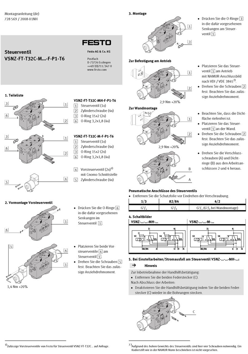
Festo
Festo VSNZ-FT-T32C-M F-P1-T6 Series Assembly instructions
Toshiba
Toshiba MD911 instruction manual

ETAS
ETAS ES313.1 user guide
Metso
Metso D Series Installation, maintenance and operation instructions
