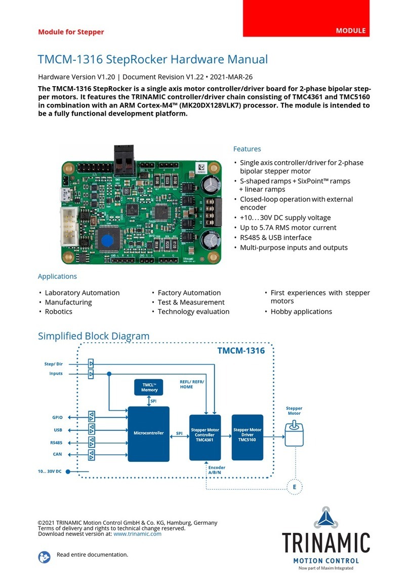
Trinamic TMCM-1633 User manual

Module for BLDC/PMSM MODULE
TMCM-1633 Hardware Manual
Hardware Version V1.00 | Document Revision V1.01 •2021-Feb-03
The TMCM-1633 is a single axis controller module for brushless DC (BLDC) and PMSM motors. It
offers field oriented control (FOC) with up-to 10A RMS phase currents at +48V DC supply. Besides
hall sensor and incremental ABN encoder interfaces for connection to the motor, digital inputs
and outputs can be used. A CAN interface allows communication with a CANopen master.
Features
•Single axis field oriented control for
BLDC/PMSM motor
•Hall and ABN encoder support
•+14,5..48V DC supply voltage
•Up to 10A RMS peak motor current
•RS232 & CAN interface
•CANopen CiA 402 drive profile
•Torque, Velocity, and Position control
Applications
•Life Sciences •Test & Measurement •Robotics / Automation
Simplified Block Diagram
controller
+14.5..55V DC
Encoder
and / or
Hall-Sensor
Signals
BLDC
Motor
MOSFET
Driver
Stage
Energy Efficient
Driver
TMC262
TMC603
3-Phase
Pre-Driver
for BLDC
motors
3-Phase
PWM
diagnostics
U
V
W
TMCM-1633
I/Os
RS232
CAN
©2021 TRINAMIC Motion Control GmbH & Co. KG, Hamburg, Germany
Terms of delivery and rights to technical change reserved.
Download newest version at: www.trinamic.com
Read entire documentation.

TMCM-1633 Hardware Manual •Hardware Version V1.00 | Document Revision V1.01 •2021-Feb-03 2 / 22
Contents
1 Features 3
1.1 General Features ............................................. 3
2 Order Codes 4
3 Mechanical and Electrical Interfacing 5
3.1 TMCM-1633 Dimensions and Weight ................................. 5
3.2 Mounting Considerations ........................................ 5
4 Connectors 6
4.1 Power Supply and Motor Connector .................................. 8
4.1.1 Power supply requirements ................................. 9
4.2 I/O, Interface and Encoder Connector ................................. 9
4.2.1 Reset the module to factory defaults ............................ 10
4.2.2 Inputs .............................................. 10
4.2.3 Encoder inputs ......................................... 11
4.2.4 Outputs ............................................. 12
5 Status LEDs 14
6 Functional Description 15
7 Operational Ratings and Characteristics 16
7.1 Absolute Maximum Ratings ....................................... 16
8 Abbreviations used in this Manual 17
9 Figures Index 18
10 Tables Index 19
11 Supplemental Directives 20
11.1 Producer Information .......................................... 20
11.2 Copyright .................................................. 20
11.3 Trademark Designations and Symbols ................................. 20
11.4 Target User ................................................ 20
11.5 Disclaimer: Life Support Systems .................................... 20
11.6 Disclaimer: Intended Use ........................................ 20
11.7 Collateral Documents & Tools ...................................... 21
12 Revision History 22
12.1 Hardware Revision ............................................ 22
12.2 Document Revision ............................................ 22
©2021 TRINAMIC Motion Control GmbH & Co. KG, Hamburg, Germany
Terms of delivery and rights to technical change reserved.
Download newest version at www.trinamic.com

TMCM-1633 Hardware Manual •Hardware Version V1.00 | Document Revision V1.01 •2021-Feb-03 3 / 22
1 Features
TMCM-1633 is a highly integrated single axis controller/driver module for brushless DC motors (BLDC)
with RS232 and CAN interface and support for CANopen. The unit (size: 50mm x 92.5mm) has been
designed in order to be plugged onto a baseboard. It offers hall sensor (TTL or open-drain) and encoder
(incremental a/b/n) inputs and additional inputs and outputs.
1.1 General Features
Main Characteristics
•Supply Voltage +24V or +48V DC nominal (+14.5 . . . +50V DC max.)
•BLDC motors with hall sensors and / or encoder are supported
•10A RMS phase current (programmable) peak
•CANopen firmware
Interfaces
•CAN
•RS232
Inputs
•2 analog inputs and 2 digital inputs
•Encoder interface (incremental ABN with differential, 5V TTL or open-drain signalling)
•Hall sensor interface (5V TTL or open-drain)
Outputs
•3 open-drain outputs
Software
•CANopen™
©2021 TRINAMIC Motion Control GmbH & Co. KG, Hamburg, Germany
Terms of delivery and rights to technical change reserved.
Download newest version at www.trinamic.com

TMCM-1633 Hardware Manual •Hardware Version V1.00 | Document Revision V1.01 •2021-Feb-03 4 / 22
2 Order Codes
Order Code Description Size (LxWxH)
TMCM-1633-2C-CANopen 1-axis BLDC plug-in controller/driver module,
FOC, 10A RMS peak, +48VDC, RS232 + CAN,
with CANopen firmware
92.5mm x 50mm x 14mm
Table 1: Order code module
©2021 TRINAMIC Motion Control GmbH & Co. KG, Hamburg, Germany
Terms of delivery and rights to technical change reserved.
Download newest version at www.trinamic.com

TMCM-1633 Hardware Manual •Hardware Version V1.00 | Document Revision V1.01 •2021-Feb-03 5 / 22
3 Mechanical and Electrical Interfacing
3.1 TMCM-1633 Dimensions and Weight
The module TMCM-1633 has a size of approximately 92.5mm x 50mm and an overall height of approx.
14mm including cononectors. It offers four mounting holes (diameter: 3.2mm).
Coordinates (x/y)
All dimensions given in mm
(5.75/11)
(0/0)
(87/11)
(4/4)
(4/46) (88.5/46)
(88.5/4)
Double row
header 2x13pins,
2.54mm pitch
Double row
header 2x13pins,
2.54mm pitch
(92.5/50)
Figure 1: TMCM-1633 mechanical dimensions
Order Code Description Dimensions in mm Weight in g
TMCM-1633-2C-CANopen 1-axis BLDC plug-in controller/-
driver module, FOC, 10A RMS
peak, +48VDC, RS232 + CAN,
with CANopen firmware
92.5mm x 50mm x 14mm ≈29
Table 2: TMCM-1633size and weight
3.2 Mounting Considerations
TMCM-1633 has been designed as a plug-in module. It usually requires a baseboard for operation. Con-
nection to the baseboard is made via two connectors at both ends of the bottom of the pcb. There are
four mounting holes for securing the board / keeping it in position in addition to the connectors. Usually
at least one screw hole at each end of the board should be used to avoid any disconnection of the board
from a baseboard during transportation or operation (vibrations inside a machine etc.).
©2021 TRINAMIC Motion Control GmbH & Co. KG, Hamburg, Germany
Terms of delivery and rights to technical change reserved.
Download newest version at www.trinamic.com

TMCM-1633 Hardware Manual •Hardware Version V1.00 | Document Revision V1.01 •2021-Feb-03 6 / 22
4 Connectors
The module offers two double row 2.54mm pitch standard connectors, one at each end of the board.
Hall1
+5V
GND
25
23
21
GND
GND
+VM
19
17
15
+VM
U
U
13
11
9
V
V
W
7
5
3
W1
Hall2
Hall3
GND
26
24
22
GND
GND
+VM
20
18
16
+VM
U
U
14
12
10
V
V
W
8
6
4
W2
Velocity
GND
Tacho
25
23
21
LED_Temp
+5V
GND
19
17
15
Enc_A-
Enc_B-
Enc_N-
13
11
9
RS232_RxD
RS232_TxD
n.c.
7
5
3
GND1
+5V
Torque
Dir_IN
1
3
5
Stop_IN
LED_Curlim
GND
7
9
11
Enc_A+
Enc_B+
Enc_N+
13
15
17
CAN_L
CAN_H
n.c.
19
21
23
GND25
I/O, interface and encoder connector Power supply and motor connector
Figure 2: TMCM-1633 Connector
Connector Connector type on-board Mating connector type
I/O, interface and encoder TSM-113-03-L-DV-K-A, 2x13 pins,
double row, 2.54mm pitch, SMT
vertical, Samtec or similar type
Samtec: SSW, SSQ, SSM, BSW, ESW,
ESQ, BCS, SLW, CES, HLE, IDSS
or IDSD series or any double row
2.54mm pitch 2x13pin female con-
nector
Power supply and motor TSM-113-03-L-DV-K-A, 2x13 pins,
double row, 2.54mm pitch, SMT
vertical, Samtec or similar type
Samtec: SSW, SSQ, SSM, BSW, ESW,
ESQ, BCS, SLW, CES, HLE, IDSS
or IDSD series or any double row
2.54mm pitch 2x13pin female con-
nector
Table 3: Connector type and mating connector of the TMCM-1633
NOTICE Do not plug-in or remove unit from baseboard during operation! This may
result in permanent damage of the unit.
NOTICE Pay attention to orientation of unit and alignment of pins when inserting
unit! Please be careful not to insert the unit the other way round. Also, please
make sure all pins are inserted into their mating pins.
©2021 TRINAMIC Motion Control GmbH & Co. KG, Hamburg, Germany
Terms of delivery and rights to technical change reserved.
Download newest version at www.trinamic.com

TMCM-1633 Hardware Manual •Hardware Version V1.00 | Document Revision V1.01 •2021-Feb-03 7 / 22
Especially for higher motor current an assembly option with a detachable screw connector is available on
request (minimum order quantity required). The 5pin connector will be assembled on top side of board
and includes power supply input (+VM and GND) and motor coil connections (U, V, W):
GND
+VM
U
V
W
Figure 3: TMCM-1633 Connector
The signals are connected 1:1 to the signals with the same label on the double-row power supply and
motor connector on the bottom side of the unit (see Figure 2). Please note that the "power supply and
motor connector" on the bottom of the PCB is still required in case the Hall sensor inputs will be used.
Connector type on-board Mating connector type
RIA AKL 330-05 5pin, 5.0mm pitch header connector 1x RIA AKL 349-05 5pin, 5.0mm pitch detach-
able screw connector (combined power supply
and motor) or 1x RIA AKL 349-02 2pin, 5.0mm
pitch detachable screw connector for power
supply input (+VM and GND) and 1x RIA AKL
349-03 3pin, 5.0mm pitch detachable screw
connector for motor coil connection (U, V, W)
Table 4: Connector type and mating connector for the high current connector option
©2021 TRINAMIC Motion Control GmbH & Co. KG, Hamburg, Germany
Terms of delivery and rights to technical change reserved.
Download newest version at www.trinamic.com

TMCM-1633 Hardware Manual •Hardware Version V1.00 | Document Revision V1.01 •2021-Feb-03 8 / 22
4.1 Power Supply and Motor Connector
A double row 26pin header with 2.54mm pitch is used for connecting all motor related signals and power
supply input.
Pin Label Description Pin Label Description
1 W Motor coil W 2 W Motor coil W
3 W Motor coil W 4 W Motor coil W
5 V Motor coil V 6 V Motor coil W
7 V Motor coil V 8 V Motor coil W
9 U Motor coil U 10 U Motor coil U
11 U Motor coil U 12 U Motor coil U
13 VM Supply input (positive) 14 VM Supply input (positive)
15 VM Supply input (positive) 16 VM Supply input (positive)
17 GND Supply input (power supply and sig-
nal ground)
18 GND Supply input (power supply and sig-
nal ground)
19 GND Supply input (power supply and sig-
nal ground)
20 GND Supply input (power supply and sig-
nal ground)
21 GND Supply input (power supply and sig-
nal ground)
22 GND Supply input (power supply and sig-
nal ground)
23 GND +5V output (100mA max.) for en-
coder and / or hall sensor supply
24 Hall3 Hall sensor 3 (+5V TTL or open-
collector) signal input
25 Hall1 Hall sensor 1 (+5V TTL or open-
collector) signal input
26 Hall2 Hall sensor 2 (+5V TTL or open-
collector) signal input
Table 5: Power Supply and Motor Connector pin assignment
NOTICE Do not connect or disconnect motor during operation! Motor cable and mo-
tor inductivity might lead to voltage spikes when the motor is (dis)connected
while energized. These voltage spikes might exceed voltage limits of the driver
MOSFETs and might permanently damage them. Therefore, always switch off
/ disconnect power supply or at least disable driver stage before connecting /
disconnecting motor.
NOTICE There is no reverse polarity protection at the supply input!
The module will short any reversed supply voltage and board electronics might
get damaged.
©2021 TRINAMIC Motion Control GmbH & Co. KG, Hamburg, Germany
Terms of delivery and rights to technical change reserved.
Download newest version at www.trinamic.com

TMCM-1633 Hardware Manual •Hardware Version V1.00 | Document Revision V1.01 •2021-Feb-03 9 / 22
4.1.1 Power supply requirements
The power supply should be able to deliver the required power and keep the supply voltage stable at
the desired maximum motor current. In no case should the supply voltage exceed the upper or lower
voltage limits. In order to be able to cope with high voltage spikes which might be caused by energy
fed back from the motor during deceleration a sufficient power supply capacitor should be added on the
baseboard close to the module. Depending on the motor and motor current please use a 4700uF or larger
capacitor with suitable voltage rating. Additionally, a suitable suppressor diode might be useful.
4.2 I/O, Interface and Encoder Connector
A double row 26pin header with 2.54mm pitch is used for connecting all GPIO, communication (CAN +
RS232) and encoder signals.
Pin Label Description Pin Label Description
1 +5V +5V analog reference as used
by the internal ADC. Max.
load 0.5mA
2 Velocity Analog input (0-10V), may be
used for velocity control in
stand-alone mode
3 Torque Analog input (0-10V), may be
used for torque / max. mo-
tor current control in stand-
alone mode
4 GND Supply input (power supply
and signal ground)
5 Dir_IN Digital input (+5V TTL). On-
board 10k pull-up resistor to
+5V. May be used as direction
input signal in stand-alone
mode
6 Tacho Digital output (open-drain).
May be used as tacho signal
output - e.g. toggles on each
hall sensor change
7 Stop_IN Digital input (+5V TTL). On-
board 10k pull-up resistor to
+5V. May be used as stop
input signal in stand-alone
mode
8 LED-Temp Digital output (open-drain).
Toggling with approx. 3Hz
when temperature pre-
warning is exceeded. Output
will be permanently pulled
low in case of overtempera-
ture of the driver stage
9 LED-Curlim Digital output (open-drain).
Will be pulled low in case cur-
rent limit has been reached
10 +5V +5V output (100mA max.) for
encoder and / or hall sensor
supply
11 GND Power supply and signal
ground
12 GND Power supply and signal
ground
13 Enc_A+ Encoder A channel (non-
inverting)
14 Enc_A- Encoder A channel (inverting)
15 Enc_B+ Encoder B channel (non-
inverting)
16 Enc_B- Encoder B channel (inverting)
17 Enc_N+ Encoder N+ channel (non-
inverting)
18 Enc_N- Encoder N channel (inverting)
19 CAN_L CAN bus signal (inverting) 20 RS232_RXD RS232 receive data input
21 CAN_H CAN bus signal (non-
inverting)
22 RS232_TXD RS232 transmit data output
©2021 TRINAMIC Motion Control GmbH & Co. KG, Hamburg, Germany
Terms of delivery and rights to technical change reserved.
Download newest version at www.trinamic.com

TMCM-1633 Hardware Manual •Hardware Version V1.00 | Document Revision V1.01 •2021-Feb-03 10 / 22
Pin Label Description Pin Label Description
23 n.c. not connected / do not con-
nect
24 n.c. not connected / do not con-
nect
25 GND Power supply and signal
ground
26 GND Power supply and signal
ground
Table 6: I/O, Interface and Encoder Connector pin assignment
4.2.1 Reset the module to factory defaults
In order to reset the module to factory default values please follow instructions listed below:
1. Switch off power cycle
2. Short input signal RS232_RXD with output signal RS232_TXD
3. Switch on power supply and wait some time
4. Switch off power supply
5. Remove short circuit
4.2.2 Inputs
The TMCM-1633 offers two analog and two digital inputs. The four inputs are availble at the 2x13pin "IO,
interface and encoder" connector.
Pin Label Type Description
2 Velocity analog Either general purpose analog input (0-10V signal) or optional velocity con-
trol input in stand alone mode
3 Torque analog Either general purpose analog input (0-10V signal) or optional torque control
/ motor max. current input in stand alone mode
5 Dir_IN digital Either general purpose digital input (+5V TTL compatible, internal 10k pull-up
to +5V) or optional direction input in stand-alone mode.
7 Stop_IN digital Either general purpose digital input (+5V TTL compatible, internal 10k pull-up
to +5V) or optional emergency stop input in stand-alone mode.
©2021 TRINAMIC Motion Control GmbH & Co. KG, Hamburg, Germany
Terms of delivery and rights to technical change reserved.
Download newest version at www.trinamic.com

TMCM-1633 Hardware Manual •Hardware Version V1.00 | Document Revision V1.01 •2021-Feb-03 11 / 22
+3.3V
Velocity
ADC input
(microcontroller)
39k2
19k1
100pF
GND
GND GND
+3.3V
Dir_IN digital input
(microcontroller)
10k
100pF
GND GND
+3.3V
Torque
ADC input
(microcontroller)
39k2
19k1
100pF
GND
GND GND
+3.3V
Stop_IN digital input
(microcontroller)
10k
100pF
GND GND
+5V
10k
+5V
10k
Figure 4: TMCM-1633 input circuit for the general purpose analog and digital inputs
4.2.3 Encoder inputs
The encoder input supports differential, +5V TTL push-pull and open-drain encoder A/B/N signals. As line
receiver for differential encoder signals a standard AM26C32 differential line receiver is used.
Pin Label Description
13 Enc_A+ Encoder A channel differential non-inverting input. Maybe used for single ended (ei-
ther TTL +5V push-pull or open-drain) channel A encoder signals, also. Please note: for
non-differential signals on-board termination resistors might have to be removed
14 Enc_A- Encoder A channel differential inverting input
15 Enc_B+ Encoder B channel differential non-inverting input. Maybe used for single ended (ei-
ther TTL +5V push-pull or open-drain) channel B encoder signals, also. Please note:
for non-differential signals on-board termination resistors might have to be removed
16 Enc_B- Encoder B channel differential non-inverting input
17 Enc_N+ Encoder Null / Zero channel differential non-inverting input. Maybe used for single
ended (either TTL +5V push-pull or open-drain) channel N encoder signals, also. Please
note: for non-differential signals on-board termination resistors might have to be re-
moved
18 Enc_N- Encoder N channel differential inverting input
©2021 TRINAMIC Motion Control GmbH & Co. KG, Hamburg, Germany
Terms of delivery and rights to technical change reserved.
Download newest version at www.trinamic.com

TMCM-1633 Hardware Manual •Hardware Version V1.00 | Document Revision V1.01 •2021-Feb-03 12 / 22
A+
A-
B+
B-
N+
N-
+5V
470R
470R
470R
GND
+5V
4k7
4k7
4k7
3k3 2k2
120R
120R
120R
ENC_A
ENC_B
ENC_N
Termination
Figure 5: TMCM-1633 encoder input circuit
The TMCM-1633 does include 120R termination resistors for differential encoder signals. In case encoder
with single ended +5V TTL push-pull or open-drain signals are used either a level converter should be
inserted or it might be necessary to remove the line termination resistors. Please see figure 6for location
of resistor array.
Figure 6: TMCM-1633 encoder termination resistor array (marked red)
4.2.4 Outputs
The TMCM-1633 offers three open-drain outputs. Two of them (LED-Temp and LED-Curlim) are connected
to on-board LEDs, in addition. Please refer to chapter 5on page 14, also.
Pin Label Description
6 Tacho This open-drain output can sink a maximum of 1A when switched on. It may be
used as general purpose output or tacho signal output, i.e. toggles on each hall
sensor change.
©2021 TRINAMIC Motion Control GmbH & Co. KG, Hamburg, Germany
Terms of delivery and rights to technical change reserved.
Download newest version at www.trinamic.com

TMCM-1633 Hardware Manual •Hardware Version V1.00 | Document Revision V1.01 •2021-Feb-03 13 / 22
Pin Label Description
8 LED-Temp This open-drain output can sink a maximum of 1A when switched on. It will toggle
with approx. 3Hz when temperature pre-warning threshold has been exceeded
and will go permanently low in case of overtemperature of the driver stage.
9 LED-Curlim This open-drain output can sink a maximum current of 1A when switched on. It
will go in case current limit of the driver stage (programmable) has been reached.
+VM
digital output
(microcontroller)
GND
220
GND
10k
1k
+5V
Tacho,
LED-Temp,
LED-Curlim
Figure 7: TMCM-1633 output circuit (same circuit design for Tacho, LED-Temp and LED-Curlim outputs)
©2021 TRINAMIC Motion Control GmbH & Co. KG, Hamburg, Germany
Terms of delivery and rights to technical change reserved.
Download newest version at www.trinamic.com

TMCM-1633 Hardware Manual •Hardware Version V1.00 | Document Revision V1.01 •2021-Feb-03 14 / 22
5 Status LEDs
The TMCM-1633 offers four on-board LEDs for power, error indication, current overload and temperature
warning. The LEDs are placed on the back side of the unit. This way they will be still visible when the unit
is plugged onto a baseboard.
Power
Error
Current overload
Temperature warning
Figure 8: TMCM-1633 LEDs
LED Color Description
Power green LED is ON, if the on-board +5V are available
Error red LED is ON in case of error
Current overload red
Flash The current limit LED flashes upon undervoltage switch
off
ON/Flash Motor PWM is reduced as the motor current limit is ex-
ceeded
Temperature warning red
Flash Driver stage temperature has exceeded pre-warning
threshold (100°C)
ON Driver stage temperature has exceeded 125°C. Driver
stage will be switched off until temperature falls below
125°C.
Table 10: LED state description
©2021 TRINAMIC Motion Control GmbH & Co. KG, Hamburg, Germany
Terms of delivery and rights to technical change reserved.
Download newest version at www.trinamic.com

TMCM-1633 Hardware Manual •Hardware Version V1.00 | Document Revision V1.01 •2021-Feb-03 15 / 22
6 Functional Description
The TMCM-1633 is a highly integrated single axis controller/driver module for brushless DC motors (BLDC)
with RS232 and CAN interface and support for CANopen. The unit (size: 50mm x 92.5mm) has been de-
signed in order to be plugged onto a baseboard. It offers hall sensor (TTL or open-drain) and encoder
(incremental a/b/n) inputs.
In Figure 9the main parts of the TMCM-1633 are shown:
•Microcontroller, responsible for overall control and 3-phase pwm generation
•Pre-driver (based on TMC603)
•power MOSFET driver bridge
•current measurement via three (low-side) shunts
•Encoder and hall sensor interfaces
•digital inputs and outputs
•CAN™interface
µC
(ARM)
Digital Inputs:
Dir_IN, Stop_IN
Outputs (Open-drain):
Tacho, LED_Temp, LED_Curlim
+14.5..+55V
DC
DC
DC
EEPROM
SPI
Encoder
and / or
Hall-Sensor
Signals
BLDC
Motor
MOSFET
Driver
Stage
Energy Efficient
Driver
TMC262
TMC603
3-Phase
Pre-Driver
for BLDC
motors
3-Phase
PWM
diagnostics
current
measurement
U
V
W
+5V +3V3
TMCM-1633
Analog Inputs:
Velocity, Torque
CAN
RS232
Figure 9: TMCM-1633 block diagram
©2021 TRINAMIC Motion Control GmbH & Co. KG, Hamburg, Germany
Terms of delivery and rights to technical change reserved.
Download newest version at www.trinamic.com

TMCM-1633 Hardware Manual •Hardware Version V1.00 | Document Revision V1.01 •2021-Feb-03 16 / 22
7 Operational Ratings and Characteristics
7.1 Absolute Maximum Ratings
Symbol Parameter Min Typ Max Unit
VSPower supply voltage for operation 14.5 24, 48 50 V
ISPower supply current 0.04 IMOT A
PID Module idle power consumption 1.2 W
I+5V +5V output for supply of external circuits (e.g. encoder and /
or hall sensors)
100 mA
IMC Continuous motor current at max. supply voltage 0 - 8 10 A
IMP Short time motor current e.g. during acceleration periods 0 - 10 A
VDIGI Input voltage on general purpose and hall sensor digital in-
puts
-0.3 +5.3V V
IOSink current on digital outputs (open-drain current) 1 A
VANA Analog input voltage 0 0 - 10 24 V
fCHOP Chopper frequency 20 kHz
T0Environmental temperature for operation at max specified
motor current (air flow might be required, depending on mo-
tor / voltage)
-25 +60 °C
Tboard Temperature of the module as measured by the on-board
sensor (NTC)
<100 125 °C
Table 11: TMCM-1633 Operational Ratings
NOTICE Never Exceed the absolute maximum ratings! Keep the power supply voltage
below the upper limit of +50V! Otherwise the board electronics will seriously be
damaged! Especially, when the selected operating voltage is near the upper limit
a regulated power supply is highly recommended.
©2021 TRINAMIC Motion Control GmbH & Co. KG, Hamburg, Germany
Terms of delivery and rights to technical change reserved.
Download newest version at www.trinamic.com

TMCM-1633 Hardware Manual •Hardware Version V1.00 | Document Revision V1.01 •2021-Feb-03 17 / 22
8 Abbreviations used in this Manual
Abbreviation Description
BLDC Brushless DC
FOC Field Oriented Control
IDE Integrated Development Environment
LED Light Emmitting Diode
RMS Root Mean Square value
TMCL TRINAMIC Motion Control Language
Table 12: Abbreviations used in this Manual
©2021 TRINAMIC Motion Control GmbH & Co. KG, Hamburg, Germany
Terms of delivery and rights to technical change reserved.
Download newest version at www.trinamic.com

TMCM-1633 Hardware Manual •Hardware Version V1.00 | Document Revision V1.01 •2021-Feb-03 18 / 22
9 Figures Index
1 TMCM-1633 mechanical dimensions . 5
2 TMCM-1633 Connector ........ 6
3 TMCM-1633 Connector ........ 7
4 TMCM-1633 input circuit for the gen-
eral purpose analog and digital inputs 11
5 TMCM-1633 encoder input circuit . . 12
6 TMCM-1633 encoder termination re-
sistor array (marked red) ....... 12
7 TMCM-1633 output circuit (same cir-
cuit design for Tacho, LED-Temp and
LED-Curlim outputs) .......... 13
8 TMCM-1633 LEDs ............ 14
9 TMCM-1633 block diagram ...... 15
©2021 TRINAMIC Motion Control GmbH & Co. KG, Hamburg, Germany
Terms of delivery and rights to technical change reserved.
Download newest version at www.trinamic.com

TMCM-1633 Hardware Manual •Hardware Version V1.00 | Document Revision V1.01 •2021-Feb-03 19 / 22
10 Tables Index
1 Order code module ........... 4
2 TMCM-1633size and weight ...... 5
3 Connector type and mating connector
of the TMCM-1633 ........... 6
4 Connector type and mating connector
for the high current connector option 7
5 Power Supply and Motor Connector
pin assignment ............. 8
6 I/O, Interface and Encoder Connector
pin assignment ............. 10
10 LED state description .......... 14
11 TMCM-1633 Operational Ratings . . . 16
12 Abbreviations used in this Manual . . 17
13 Hardware Revision ........... 22
14 Document Revision ........... 22
©2021 TRINAMIC Motion Control GmbH & Co. KG, Hamburg, Germany
Terms of delivery and rights to technical change reserved.
Download newest version at www.trinamic.com

TMCM-1633 Hardware Manual •Hardware Version V1.00 | Document Revision V1.01 •2021-Feb-03 20 / 22
11 Supplemental Directives
11.1 Producer Information
11.2 Copyright
TRINAMIC owns the content of this user manual in its entirety, including but not limited to pictures, logos,
trademarks, and resources. ©Copyright 2021 TRINAMIC. All rights reserved. Electronically published by
TRINAMIC, Germany.
Redistributions of source or derived format (for example, Portable Document Format or Hypertext Markup
Language) must retain the above copyright notice, and the complete Datasheet User Manual documen-
tation of this product including associated Application Notes; and a reference to other available product-
related documentation.
11.3 Trademark Designations and Symbols
Trademark designations and symbols used in this documentation indicate that a product or feature is
owned and registered as trademark and/or patent either by TRINAMIC or by other manufacturers, whose
products are used or referred to in combination with TRINAMIC’s products and TRINAMIC’s product doc-
umentation.
This Hardware Manual is a non-commercial publication that seeks to provide concise scientific and tech-
nical user information to the target user. Thus, trademark designations and symbols are only entered in
the Short Spec of this document that introduces the product at a quick glance. The trademark designation
/symbol is also entered when the product or feature name occurs for the first time in the document. All
trademarks and brand names used are property of their respective owners.
11.4 Target User
The documentation provided here, is for programmers and engineers only, who are equipped with the
necessary skills and have been trained to work with this type of product.
The Target User knows how to responsibly make use of this product without causing harm to himself or
others, and without causing damage to systems or devices, in which the user incorporates the product.
11.5 Disclaimer: Life Support Systems
TRINAMIC Motion Control GmbH & Co. KG does not authorize or warrant any of its products for use in
life support systems, without the specific written consent of TRINAMIC Motion Control GmbH & Co. KG.
Life support systems are equipment intended to support or sustain life, and whose failure to perform,
when properly used in accordance with instructions provided, can be reasonably expected to result in
personal injury or death.
Information given in this document is believed to be accurate and reliable. However, no responsibility
is assumed for the consequences of its use nor for any infringement of patents or other rights of third
parties which may result from its use. Specifications are subject to change without notice.
11.6 Disclaimer: Intended Use
The data specified in this user manual is intended solely for the purpose of product description. No rep-
resentations or warranties, either express or implied, of merchantability, fitness for a particular purpose
©2021 TRINAMIC Motion Control GmbH & Co. KG, Hamburg, Germany
Terms of delivery and rights to technical change reserved.
Download newest version at www.trinamic.com
Table of contents
Other Trinamic Computer Hardware manuals

Trinamic
Trinamic BB-100 User manual
Trinamic
Trinamic TMCM-1230 User manual
Trinamic
Trinamic TMCM-035 User manual
Trinamic
Trinamic TMCM-160 User manual

Trinamic
Trinamic TMCL TMCM-142 Use and care manual

Trinamic
Trinamic TMCM-1161 User manual
Trinamic
Trinamic TMCM-101 User manual
Trinamic
Trinamic PANdrive PD42-1- 1243-IOLINK Safety guide

Trinamic
Trinamic PD 108-28-SE-485 Series User manual
Trinamic
Trinamic TMCM-310 User manual
