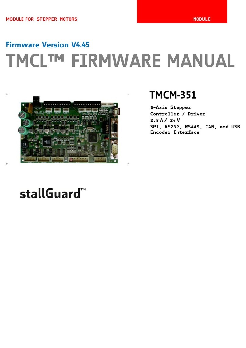
Trinamic TMCM-351 User manual

TMCM-351 Manual (V1.01 / May 25nd, 2009) 2
Copyright © 2008, TRINAMIC Motion Control GmbH & Co. KG
Table of Contents
1Life support policy ....................................................................................................................................................... 3
2Features........................................................................................................................................................................... 4
3Order codes.................................................................................................................................................................... 5
4Mechanical and Electrical Interfacing ..................................................................................................................... 6
4.1 Board size and mounting holes...................................................................................................................... 6
4.2 Connectors............................................................................................................................................................. 7
4.2.1 Power connector............................................................................................................................................ 8
4.2.2 Motor connector............................................................................................................................................. 8
4.2.3 Reference connector ..................................................................................................................................... 9
4.2.4 Analogue input connector .......................................................................................................................... 9
4.2.5 USB connector ..............................................................................................................................................10
4.2.6 RS232 connector ..........................................................................................................................................10
4.2.7 CAN connector..............................................................................................................................................10
4.2.8 RS485 connector ..........................................................................................................................................11
4.2.9 SPI connector ............................................................................................................................................... 11
4.2.10 I/O connector................................................................................................................................................11
4.2.11 Encoder_0/1/2 connector ...........................................................................................................................12
4.3 Jumpers.................................................................................................................................................................13
4.3.1 J1: RS485 bus termination.........................................................................................................................13
4.3.2 J2: RS232 / RS485 interface selection.....................................................................................................13
4.3.3 J3: CAN bus termination ............................................................................................................................13
4.3.4 J4 –J12: Encoder input termination.......................................................................................................13
5Operational Ratings ...................................................................................................................................................14
6Revision History ..........................................................................................................................................................15
6.1 Document Revision ...........................................................................................................................................15
6.2 Hardware Revision ............................................................................................................................................15

TMCM-351 Manual (V1.01 / May 25nd, 2009) 3
Copyright © 2008, TRINAMIC Motion Control GmbH & Co. KG
1Life support policy
TRINAMIC Motion Control GmbH & Co. KG does not
authorize or warrant any of its products for use in life
support systems, without the specific written consent of
TRINAMIC Motion Control GmbH & Co. KG.
Life support systems are equipment intended to support or
sustain life, and whose failure to perform, when properly
used in accordance with instructions provided, can be
reasonably expected to result in personal injury or death.
© TRINAMIC Motion Control GmbH & Co. KG 2005
Information given in this data sheet is believed to be
accurate and reliable. However no responsibility is assumed
for the consequences of its use nor for any infringement of
patents or other rights of third parties, which may result
form its use.
Specifications subject to change without notice.

TMCM-351 Manual (V1.01 / May 25nd, 2009) 4
Copyright © 2008, TRINAMIC Motion Control GmbH & Co. KG
2Features
The TMCM-351 is a powerful three axes bipolar stepper motor controller / driver board with optional encoder
interface for all three axes and a large number of general purpose digital and analogue input / outputs.
Several different serial communication interfaces are available.
Electrical data
Supply voltage: +24V DC nominal (28.5V DC max.)
Motor current: up-to 2.8A RMS per axis (programmable)
Stepper motor data
two phase bipolar stepper motors with up-to 2.8A RMS coil current
optional incremental encoder interface (a/b/n), accepts differential or single ended input signals
Interfaces
2 reference switch inputs per motor axis (6 altogether, internal pull-up resistors, +24V compatible)
8 general purpose inputs (+24V compatible)
8 general purpose outputs incl. two power outputs (all open-collector)
1 shutdown input (enable / disable driver stage in hardware)
4 dedicated analogue inputs (programmable 3.3V / 10V input range)
SPI connector with three chip select signals for I/O extension
RS-232, RS-485, CAN and USB serial communication interfaces
Features
High-efficient operation, low power-dissipation (TMC249 stepper driver with external MOSFETs)
Dynamic current control
Integrated Protection
On the fly alteration of motor parameters (e.g. position, velocity, acceleration)
Motion profile calculation in real-time (TMC428 motion controller)
Each axis individually and independently programmable
Supports up-to 64 microsteps per fullstep
Integrated stallGuardTM for motor stall detection (e.g. elimination of end switches)
Closed-loop operation with TMCL possible (when using the optional incremental encoder interface)
Software
TMCL remote (direct mode) or stand-alone operation (memory for 2048 TMCL commands)
Fully supported by TMCL-IDE (PC based integrated development environment)
Optional CANopen firmware

TMCM-351 Manual (V1.01 / May 25nd, 2009) 5
Copyright © 2008, TRINAMIC Motion Control GmbH & Co. KG
3Order codes
The TMCM-351 is available with optional encoder interface and with standard TMCL firmware or CANopen
firmware:
Order code
Description
Dimensions [mm2]
TMCM-351
TMCM-351 without encoder interface with TMCL firmware
160mm x 100mm
TMCM-351-CANopen
TMCM-351 without encoder interface with CANopen firmware
160mm x 100mm
TMCM-351-E
TMCM-351 with encoder interface and TMCL firmware
160mm x 100mm
TMCM-351-E-CANopen
TMCM-351 with encoder interface and CANopen firmware
160mm x 100mm
Table 3.1: Order codes

TMCM-351 Manual (V1.01 / May 25nd, 2009) 6
Copyright © 2008, TRINAMIC Motion Control GmbH & Co. KG
4Mechanical and Electrical Interfacing
4.1 Board size and mounting holes
The TMCM-351 three axes controller driver board has a board size of 160mm x 100mm (standard euro board
format). There are four mounting holes altogether for M3 screws placed at a distance of 4mm from each
corner of the board (Figure 4.1).
4mm
4mm
160mm
100mm
4mm
4mm
4mm
4mm
4mm
4mm
R3.2mm R3.2mm
R3.2mm
R3.2mm
Figure 4.1 TMCM-351 controller / driver board

TMCM-351 Manual (V1.01 / May 25nd, 2009) 7
Copyright © 2008, TRINAMIC Motion Control GmbH & Co. KG
4.2 Connectors
The TMCM-351 has connectors for three motors, related reference switches, three encoders (only with
encoder option), analogue and digital inputs and outputs and several serial interfaces (RS232, RS485, CAN
and USB).
Analog input 0 / 1
connector
Encoder_0
connector
Encoder_1
connector
Encoder_2
connector
I/O
connector
SPI
connector
CAN
connector
RS232
connector
USB
connector
Reference
connector
Motor
connector
Power
connector
RS485
connector
J1: RS485 bus termination
J2: RS232 / RS485 selection
J3: CAN bus termination
Analog input 2 / 3
connector
J4 - J12: Encoder input termination
Figure 4.2 TMCM-351 connectors

TMCM-351 Manual (V1.01 / May 25nd, 2009) 8
Copyright © 2008, TRINAMIC Motion Control GmbH & Co. KG
4.2.1 Power connector
A 2-pin detachable screw connector is used for power supply.
12
Pin
Label
Description
1
GND
Module ground (power supply and signal ground)
2
VDD
Power supply input, nom. +24V DC (+7 .. +28.5V DC)
Table 4.1: Power connector
4.2.2 Motor connector
For the three motors there are two connector options: either one detachable screw connector (for
prototyping, smaller series) or three separate crimp connectors (for higher volume series).
112
Pin
Label
Description
1
Motor_0_B-
Motor 0, coil B
2
Motor_0_B+
Motor 0, coil B
3
Motor_0_A-
Motor 0, coil A
4
Motor_0_A+
Motor 0, coil A
5
Motor_1_B-
Motor 1, coil B
6
Motor_1_B+
Motor 1, coil B
7
Motor_1_A-
Motor 1, coil A
8
Motor_1_A+
Motor 1, coil A
9
Motor_2_B-
Motor 2, coil B
10
Motor_2_B+
Motor 2, coil B
11
Motor_2_A-
Motor 2, coil A
12
Motor_2_A+
Motor 2, coil A
Table 4.2: Motor connector (detachable screw connector)
1 4
Pin
Label
Description
1
Motor_0/1/2_B-
Motor 0/1/2, coil B
2
Motor_0/1/2_B+
Motor 0/1/2, coil B
3
Motor_0/1/2_A-
Motor 0/1/2, coil A
4
Motor_0/1/2_A+
Motor 0/1/2, coil A
Table 4.3: Motor connector (crimp connector)

TMCM-351 Manual (V1.01 / May 25nd, 2009) 9
Copyright © 2008, TRINAMIC Motion Control GmbH & Co. KG
4.2.3 Reference connector
For the reference switch inputs (two reference switch inputs are supported for each motor) there are two
connector options: either one detachable screw connector (for prototyping, smaller series) or three separate
crimp connectors (for higher volume series).
112
Pin
Label
Description
1
REF_0_R
Motor 0, right reference / stop switch input
2
REF_0_L
Motor 0, left reference / stop switch input
3
GND
System / module ground
4
+5V
+5V supply output for active switches
5
REF_1_R
Motor 1, right reference / stop switch input
6
REF_1_L
Motor 1, left reference / stop switch input
7
GND
System / module ground
8
+5V
+5V supply output for active switches
9
REF_2_R
Motor 1, right reference / stop switch input
10
REF_2_L
Motor 1, left reference / stop switch input
11
GND
System / module ground
12
+5V
+5V supply output for active switches
Table 4.4: Reference connector (detachable screw connector)
1 4
Pin
Label
Description
1
REF_0/1/2_R
Motor 0/1/2, right reference / stop switch input
2
REF_0/1/2_L
Motor 0/1/2, left reference / stop switch input
3
GND
System / module ground
4
+5V
+5V supply output for active switches
Table 4.5: Reference connector (crimp connector)
4.2.4 Analogue input connector
The board has four dedicated analogue inputs with programmable input range (either 0..+3.3V or 0..+10V).
There are two connectors with two analogue inputs connected to each connector
1 4
Pin
Label
Description
1
Analogue_0/2
Analogue input 0 / 2
2
GND
System / module ground
3
Analogue_1/3
Analogue input 1/3
4
GND
System / module ground
Table 4.6: Analogue input connector

TMCM-351 Manual (V1.01 / May 25nd, 2009) 10
Copyright © 2008, TRINAMIC Motion Control GmbH & Co. KG
4.2.5 USB connector
The board includes a USB interface for serial communication. A standard USB type B connector is used for
this purpose. USB is one out of four different interfaces available for communication with the board.
1
2
4
3
Pin
Label
Description
1
+5V
Board is self-powered –just use to detect availability
of attached host system (e.g. PC)
2
USB-
Differential USB bus
3
USB+
Differential USB bus
4
GND
System / module ground
Table 4.7: USB connector
4.2.6 RS232 connector
The board includes an RS232 interface for serial communication. A standard DSUB 9-pin female connector is
used for this purpose. RS232 is one out of four different interfaces available for communication with the
board.
5 1
9 6
Pin
Label
Description
2
RS232_TxD
RS232 transmit serial data
3
RS232_RxD
RS232 receive serial data
5
GND
System / board ground
1, 4, 6, 7, 8, 9
n.c.
Pins not used / not connected
Table 4.8: RS232 connector
Attention: please verify setting of J2 (selection of RS232 / RS485 interface) for proper operation of the
RS232 connection.
4.2.7 CAN connector
The board includes a CAN interface for serial communication. A standard DSUB 9-pin male connector is used
for this purpose. CAN is one out of four different interfaces available for communication with the board.
1 5
6 9
Pin
Label
Description
2
CAN_L
CAN differential bus
7
CAN_H
CAN differential bus
3, 6
GND
System / board ground
n.c.
Pins not used / not connected
Table 4.9: CAN connector
Attention: please verify setting of J3 (CAN bus termination) for proper operation of the CAN connection.

TMCM-351 Manual (V1.01 / May 25nd, 2009) 11
Copyright © 2008, TRINAMIC Motion Control GmbH & Co. KG
4.2.8 RS485 connector
The board includes an RS485 interface for serial communication. A 4-pin detachable screw connector is used
for this purpose. RS485 is one out of four different interfaces available for communication with the board.
1
4
Pin
Label
Description
1
RS485+
RS485 differential bus (connected to pin 3)
2
RS485-
RS485 differential bus (connected to pin 4)
3
RS485+
RS485 differential bus (connected to pin 1)
4
RS285-
RS485 differential bus (connected to pin 2)
Table 4.10: RS485 connector
Attention: please verify settings of J1 (RS485 bus termination) and J2 (selection of RS232 / RS485
interface) for proper operation of the RS485 connection.
4.2.9 SPI connector
For extension of the available inputs and outputs an SPI interface is available. A standard 2.54mm pitch two
row header is used as connector for the external SPI interface.
1
2
9
10
Pin
Label
Pin
Label
1
SPI_MOSI
2
GND
3
SPI_MISO
4
GND
5
SPI_CLK
6
GND
7
SPI_SEL0
8
SPI_SEL2
9
SPI_SEL1
10
+5V_output
Table 4.11: SPI connector
4.2.10 I/O connector
The I/O connector offers 8 digital and analogue inputs and 8 digital outputs. All inputs are +24V compatible.
All outputs offer open collector driver stages. OUT_0/1/2/3/4/5 can sink up-to 100mA, OUT_6/7 are more
powerful and can drive up-to 2A. A standard 2.54mm pitch two row header is used for this connector.
Attention: /Shutdown input pin has to be connected to supply voltage in order to enable driver stages
for all three stepper motor axes. A jumper between pin 19 and pin 20 can be used to permanently
enable drivers (see picture on front page).
1
2
20
19
Pin
Label
Pin
Label
1
OUT_0
2
OUT_1
3
OUT_2
4
OUT_3
5
OUT_4
6
OUT_5
7
OUT_6
8
OUT_7
9
+5V_output
10
GND
11
IN_0
12
IN_1
13
IN_2
14
IN_3
15
IN_4
16
IN_5
17
IN_6
18
IN_7
19
/Shutdown
20
VDD
Table 4.12: I/O connector

TMCM-351 Manual (V1.01 / May 25nd, 2009) 12
Copyright © 2008, TRINAMIC Motion Control GmbH & Co. KG
4.2.11 Encoder_0/1/2 connector
These three connectors (one encoder interface connector per axis) will be available only for boards with
assembled encoder option. A standard 2.54mm pitch two row header is used for connecting an encoder.
Differential and single ended incremental encoders with / without zero / index channel are supported.
1
2
9
10
Pin
Label
Pin
Label
1
GND
2
GND
3
Encoder_0/1/2_N+
4
Encoder_0/1/2_N-
5
Encoder_0/1/2_A+
6
Encoder_0/1/2_A-
7
+5V_output
8
+5V_output
9
Encoder_0/1/2_B+
10
Encoder_0/1/2_B-
Table 4.13: Encoder connector

TMCM-351 Manual (V1.01 / May 25nd, 2009) 13
Copyright © 2008, TRINAMIC Motion Control GmbH & Co. KG
4.3 Jumpers
Most settings of the board are done through the software. Nevertheless, a few jumpers are available for
configuration.
4.3.1 J1: RS485 bus termination
The board includes a 120 Ohm resistor for proper bus termination of the RS485 interface. When this jumper
is closed, the resistor will be placed between the two differential bus lines RS485+ and RS485-.
4.3.2 J2: RS232 / RS485 interface selection
This 3-pin single row header is used for selecting one of two desired serial interfaces: RS232 or RS485 using
a jumper:
RS232 interface
selection
RS485 interface
selection
4.3.3 J3: CAN bus termination
The board includes a 120 Ohm resistor for proper bus termination of the CAN interface. When this jumper is
closed, the resistor will be placed between the two differential bus lines CAN_H and CAN_L.
4.3.4 J4 –J12: Encoder input termination
For enhanced reliability differential encoder signals should be terminated properly. The board offers
termination resistors (120 Ohm) for all three encoder interface signals (a/b/n) for all three encoders. By
setting jumpers, these resistors will be placed between the differential encoder signals. Do not set these
jumpers in case encoders with single ended signals are used.
Place jumpers for
proper temrination

TMCM-351 Manual (V1.01 / May 25nd, 2009) 14
Copyright © 2008, TRINAMIC Motion Control GmbH & Co. KG
5Operational Ratings
The operational ratings shown below should be used as design values. In no case should the maximum
values been exceeded during operation.
Symbol
Parameter
Min
Typ
Max
Unit
VDD
Power supply voltage for operation
7
24
28.5
V
ICOIL_peak
Motor coil current for sine wave
peak (chopper regulated, adjustable
via software)
0
4
A
ICOIL_RMS
Continuous motor current (RMS)
0
2.8
A
ISUPPLY
Power supply current
<< ICOIL
1.4 * ICOIL
A
TENV
Environment temperature at rated
current (no forced cooling required)
-20
+40
°C
Environment temperature at 80% of
rated current or 50% duty cycle
(no forced cooling required)
-20
+60
°C
Table 5.1: General operational ratings of the module

TMCM-351 Manual (V1.01 / May 25nd, 2009) 15
Copyright © 2008, TRINAMIC Motion Control GmbH & Co. KG
6Revision History
6.1 Document Revision
Version
Date
Author
Description
1.00
2008-10-22
GE
Initial version
1.01
2009-05-25
OE
Encoder input pinning corrected
Table 6.1: Document Revision
6.2 Hardware Revision
Version
Date
Description
1.00
2008-08-25
First prototypes
Table 6.2: Hardware Revision
Other manuals for TMCM-351
4
Table of contents
Other Trinamic Computer Hardware manuals
Trinamic
Trinamic PANdrive PD013-42 User manual

Trinamic
Trinamic BB-100 User manual
Trinamic
Trinamic TMCM-035 User manual
Trinamic
Trinamic PANdrive PD42-1- 1243-IOLINK Safety guide

Trinamic
Trinamic TMCM-1161 User manual
Trinamic
Trinamic TMCM-1316 StepRocker User manual

Trinamic
Trinamic TMCL TMCM-142 Use and care manual
Trinamic
Trinamic TMCM-1230 User manual
Trinamic
Trinamic PD-109 User manual
Trinamic
Trinamic CANopen User manual

