Trinity Highway CAT-350 User manual


TrinityHighway.com 1 Part Number: 620291
©2021 Trinity Highway Products, LLC
December 2021
CAT®-350 System
Tangent Double-Sided End Terminal
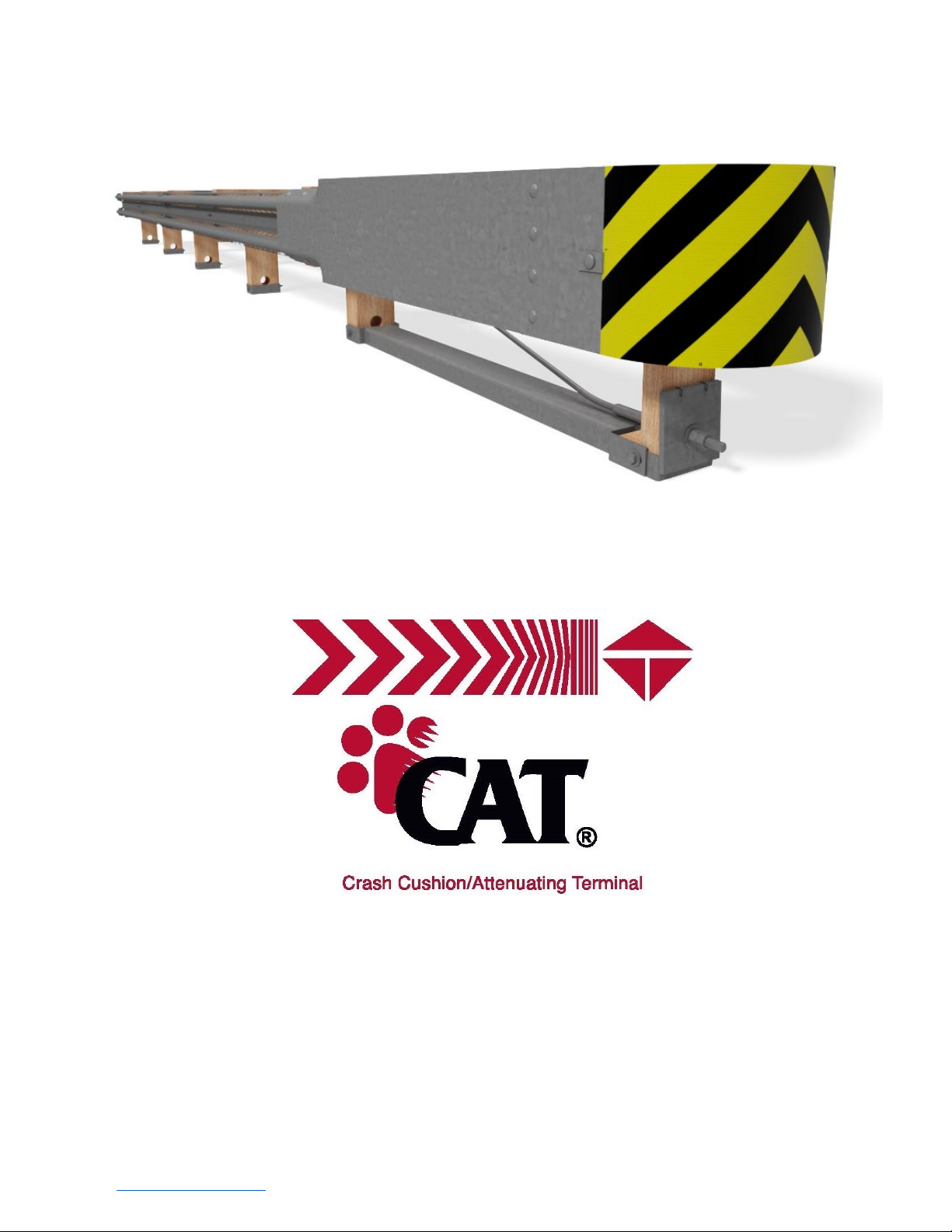
The Crash Cushion Attenuating Terminal (“CAT®”) has been tested to National Cooperative Highway
Research Program (“NCHRP”) Report 350 criteria and has been deemed eligible for Federal-aid
reimbursement on the National Highway System (“NHS”) by the Federal Highway Administration (“FHWA”).
Product Description
Assembly Manual
15601 Dallas Parkway
Suite 525
Addison, Texas 75001
Warning: The local highway agency, distributors, owners, and contractors are
RESPONSIBLE for the assembly, maintenance, and repair of the CAT®. Failure to fulfill
these RESPONSIBILITIES with respect to the assembly, maintenance, and repair of the
CAT® could result in serious injury or death.
Important: These instructions are for standard assembly specified by the appropriate highway
agency. In the event the specified system assembly, maintenance, or repair would require a
deviation from standard assembly parameters, contact a Trinity Highway Products, LLC (“Trinity
Highway”) representative. This system has been deemed eligible by the FHWA for use on the
NHS under strict criteria utilized by that agency.
This manual must be available to the worker overseeing and/or assembling the product at all times. For
additional copies, contact Trinity Highway at (888) 356-2363 or visit TrinityHighway.com/Products.
The information contained in this manual supersede all previous versions. The instructions, illustrations, and
specifications are based on the latest CAT® System information available to Trinity Highway at publication. We
reserve the right to make changes at any time. Please visit TrinityHighway.com/product-category/end terminals
to confirm the latest revision.

TrinityHighway.com
2
December 2021
Crash Cushion Attenuating Terminal
The CAT® is a tangent, double-sided, re-directive/gating and energy absorbing attenuator/end terminal
available for use with various longitudinal highway barriers, in either unidirectional or bidirectional traffic
applications.

TrinityHighway.com
3
December 2021
Table of Contents
CAT® ACRONYMS ............................................................................................................................................. 4
Customer Service Contacts .................................................................................................................................. 4
Limitations and Warnings .................................................................................................................................... 5
Overview ............................................................................................................................................................. 6
Recommended Tools ........................................................................................................................................... 7
Site Preparation ................................................................................................................................................... 8
Post Placement ................................................................................................................................................... 9
Rigid Pavement and Rock ................................................................................................................................... 9
Inspect Shipment ................................................................................................................................................ 9
CAT® System Components/Hardware................................................................................................................ 12
Assembly Steps ................................................................................................................................................. 17
STEP 1A: CAT® and CAT® Tail – Post Layout 1-8 Connecting To 27 3/4” [705 mm] High Downstream
Single/Double Sided Guardrail .................................................................................................. 18
STEP 1B: CAT® and CAT® Tail – Post Layout 1-11 Connecting To 31” [787 mm] High Downstream
Single/Double Sided Guardrail................................................................................................... 19
STEP 2A: CAT® Tail - Post Assembly 7 & 8 Connecting To 27 3/4” [705 mm] High Downstream Single/
Double Sided Guardrail............................................................................................................. 20
STEP 2B: CAT® Tail - Post Assembly 7-11 Connecting To 31” [787 mm] High Down Stream Guardrail .... 21
STEP 3: CAT® Tube Assembly Short Tube 4’-6” [1.37 m] with Soil plate; Long Tube 6’-0” [1.83 m] ......... 22
STEP 4A: CAT® Post and Offset Block Assembly (Posts 3, 5, & 6) ........................................................... 23
STEP 4B: CAT® Post Assembly (Post 4) .................................................................................................. 24
STEP 4C: CAT® Post and Strut Assembly (Posts 1 & 2) ........................................................................... 25
STEP 5A: CAT® Tail - Guardrail Assembly Connecting To 27 3/4” [705 mm] High Downstream Single
Sided Guardrail ......................................................................................................................... 26
STEP 5B: CAT® Tail Anchor Bracket Assembly (For 27 3/4” [705 mm] High Downstream Single Sided
Guardrail Assembly) .................................................................................................................. 27
STEP 5C: CAT® Tail - Anchor Assembly Connecting To 27 3/4” [705] High Downstream Single Sided
Guardrail ................................................................................................................................... 28
STEP 6: CAT® Tail - Guardrail Assembly Connecting To 27 3/4” [705 mm] High Downstream Double
Sided Guardrail ......................................................................................................................... 29
STEP 7A: CAT® Tail - Guardrail Assembly Connecting To 31” [787 mm] High, 8” [200 mm] Offset Blocks,
MGS Downstream Guardrail ..................................................................................................... 30
STEP 7B: CAT® Tail - Guardrail Assembly Connecting To 31” [787 mm] High, 12” [300 mm] Offset
Blocks, MGS Downstream Guardrail ......................................................................................... 31
STEP 8: CAT® Tail - Guardrail Assembly With 9’- 4 1/2” Guardrail Panel Connecting To 31” [787 mm]
High Downstream MGS Guardrail ............................................................................................. 32
STEP 9A: CAT® 10 Gauge, Slotted/Welded Guardrail-2 Assembly ............................................................ 33
STEP 9B: CAT® Splice Assembly (At Post 6)............................................................................................. 34
STEP 10A: CAT® 12 Gauge, Slotted Guardrail-1 Assembly ......................................................................... 35
STEP 10B: CAT® Splice Assembly (At Post 4)............................................................................................. 36
STEP 10C: CAT® Spacer Assembly ............................................................................................................ 37
STEP 11: CAT® Nose Plate (10 Gauge) Assembly .................................................................................... 38
STEP 12: CAT® Side Plate (10 Gauge) Assembly .................................................................................... 39
STEP 13: CAT® Anchor Cable Assembly ................................................................................................... 40
STEP 14: CAT® Restraining Road Assembly (Posts 3 & 5) ........................................................................ 41
STEP 15: CAT® Knock Out Tube/Post Plate Assembly (Posts 4 & 6) ......................................................... 42
STEP 16: CAT® Delineation ...................................................................................................................... 43
CAT® System Assembly Checklist (File with Project Records) ........................................................................... 44
CAT® System Repair Checklist (File with Maintenance Records) ....................................................................... 45
CAT® System Routine Inspection Checklist (File with Maintenance Records) .................................................... 46
APPENDIX A: AASHTO Roadside Design Guide Roadside (Shoulder) Grading Detail ....................................... 47
APPENDIX B: AASHTO Roadside Design Guide Median Grading Detail ........................................................... 48
APPENDIX C: CAT® SS245 Repair Kit1 and CAT® Hardware Bags ................................................................. 49
NOTES .............................................................................................................................................................. 50

TrinityHighway.com
4
December 2021
CAT® ACRONYMS
AASHTO American Association of State Highway and Transportation Officials
BLON Beginning Length of Need
CAT® Crash Cushion Attenuating Terminal
CFR Code of Federal Regulation
FHWA Federal Highway Administration
MUTCD Manual on Uniform Traffic Control Devices
NCHRP National Cooperative Highway Research Program
NHS National Highway System
OSHA Occupational Safety & Health Administration
PPE Personal Protective Equipment
TL-3 Test Level-3
Trinity Highway Trinity Highway Products, LLC
Customer Service Contacts
Trinity Highway is committed to the highest level of customer service. Feedback regarding the
CAT®, its assembly procedures, supporting documentation, and performance is always welcome.
Additional information can be obtained from the contact information below:
Trinity Highway
Telephone
(888) 356-2363 (USA)
+1 214 589 8140 (International)
Contact Link
TrinityHighway.com/Products
Website:
www.trinityhighway.com
Trinity Highway Products, LLC
15601 Dallas Parkway
Suite 525
Addison, TX 75001

TrinityHighway.com
5
December 2021
Limitations and Warnings
Trinity Highway, in compliance with NCHRP Report
350, contracts with ISO 17025 A2LA accredited
testing laboratories to perform crash tests, evaluate
tests, and submit the test results to the FHWA for
review.
The CAT® System has been deemed eligible
by FHWA as meeting the requirements and
guidelines of NCHRP Report 350, Test Level 3
(“TL-3”). These tests typically evaluate product
performance defined by NCHRP Report 350
involving a range of vehicles on roadways,
from lightweight cars (approx. 800 kg [1,800 lb.])
and full size pickup trucks (approx. 2,000 kg [4400
lb.]) at 100 kph [62 mph].
The CAT® is tested pursuant to the test matrix
criteria of NCHRP Report 350 as designated by
FHWA. The FHWA tests are not intended to
represent the performance of systems when
impacted by every vehicle type or in every
impact condition existing on the roadway. Every
departure from the roadway is a unique event.
Trinity Highway expressly disclaims any warranty or
liability for injury or damage to persons or property
resulting from any impact, collision or harmful
contact with its products, other vehicles, or nearby
hazards or objects by any vehicle, object or person,
whether or not the products were assembled in
consultation with Trinity Highway or by third parties.
The CAT® is intended to be assembled, delineated,
and maintained within the state/specifying agency and
federal guidelines. It is important for the
state/specifying agency to select the most appropriate
product configuration for site specifications.
The state/specifying agency’s careful evaluation of
the site layout, vehicle population type and speed,
traffic direction, and visibility are some of the
elements that require evaluation in the selection of
a highway product. For example, curbs could cause
an untested effect on an impacting vehicle.
After an impact with the system, all debris must be
removed from the area immediately in compliance with
the most applicable state/specifying agency policy. The
specified CAT® must be evaluated and restored to its
original specified condition or replaced as the
state/specifying agency determines/requires, as soon
as possible. Product selection, approval, proper
installation, and maintenance of any highway product is
the sole responsibility of the state/specifying agency.
Safety Alert Symbols appear throughout this
manual and indicate Danger, Warning, Caution or
Important statements. Failure to read and follow
these warnings could result in serious injury or
death in the event of a vehicle impact with the
system.
WARNING: Do not assemble, maintain, or repair
the CAT® until you have read this manual
thoroughly and completely understand it. Ensure
that all Danger, Warning, Caution, and
Important
statements within the manual are completely
followed. Please call Trinity Highway at (888)
356-2363 if you have any questions about
instructions in this manual.
WARNING: Safety measures incorporating
appropriate traffic control devices and personal
protective equipment ("PPE") specified by the
state/specifying agency must be used to protect
all personnel while at the assembly,
maintenance, or repair site. Work gloves, apron,
eye protection,
safety-toe
shoes,
and
back
protection shall be used.
WARNING: Ensure the assembly site meets all
appropriate Manual on Uniform Traffic Control
Devices (“MUTCD”) and the state/specifying
agency standards.
WARNING: Use only Trinity Highway parts that are
specified by Trinity Highway for use with the CAT®
for assembling, maintaining, or repairing the
CAT®. Do not utilize or otherwise commingle
parts from other systems even if those systems
are other Trinity Highway Systems. Such
configurations have not been tested, nor have they
been approved for use.
Assembly,
maintenance or
repairs using unspecified parts or accessories is
strictly prohibited. Failure to follow this
warning could result in serious injury or death
in the event of a vehicle impact with such an
UNACCEPTED system.
WARNING: Do NOT modify the CAT® in any way.
IMPORTANT: Trinity Highway makes no
recommendation whether use or reuse of any part
of the CAT® is appropriate or acceptable after
system impact. It is the responsibility of the
state/specifying agency and its engineers to make
that determination.
IMPORTANT: It is the responsibility of owner,
state/specifying agency, or specifier to inspect the
CAT® after assembly is complete to ensure the
instructions provided in this manual have been
strictly followed.

TrinityHighway.com
6
December 2021
Overview
The CAT® is a tangent, double-sided, re-directive/gating and energy absorbing attenuator/end terminal
available for use with various longitudinal highway barriers, in either unidirectional or bidirectional traffic
applications.
The CAT® consists of CAT® 10/12 gauge slotted guardrail, CAT® 10 gauge nose/side plates, channel strut,
CAT® anchor cable, CAT® treated wood posts/blocks, tube sleeves and various other required hardware
accessories.
The CAT® requires a 12’-6” [3.81 m] CAT® Tail; Single Sided or Double Sided.
The Single Sided CAT® Tail is used when the CAT® is connected to a single sided guardrail assembly.
• Ensure this CAT® Tail is not used in a median application where the opposing traffic can impact the blunt
end of the CAT® Tail Guardrail, if it is inside the Clear Zone as defined by Roadside Design Guide (latest
edition).
• See drawing SS220 when using 27 3/4” [705 mm] height downstream single sided guardrail assembly.
The Double Sided CAT® Tail is used when the CAT® is connected to a double sided guardrail assembly.
• See drawing SS224 when using 27 3/4” [705 mm] height downstream double sided guardrail assembly.
• See drawing SS695/SS696 when using 31” [787 mm] height downstream double sided guardrail assembly.
When used with rigid barriers, (i.e. concrete barrier, wall or bridge pier) a semi to rigid barrier
transition will be required (see state/specifying agency standards) as well as an appropriate CAT®
Tail.

TrinityHighway.com
7
December 2021
Recommended Tools
Documentation
•
Manufacturer’s CAT® System Product Description Assembly Manual (Current Version).
•
CAT® System Drawing(s). Current Version of Applicable CAT® and CAT® Tail Drawing.
Personal Protective Equipment
•
Eye Protection
•
Work Gloves
•
Safety-Toe Shoes
•
Back Protection
•
Hard Hat
•
Reflective Vest
•
Apron
Miscellaneous
•
Traffic Control Equipment and Plan per state/specifying agency standards and the MUTCD.
•
SAE Combination Wrench Set
•
Socket Set & Socket Wrench
•
Hammer
•
Chalk Line
•
Tape Measure
•
Marking Paint and Pen
•
Straight Edge
•
Level
•
Plumb Line
•
Post Pounder (commonly used for driving posts)
•
Auger
•
Soil Tamper
•
5/8” Alignment Tool (Drift Pin)
•
Locking Pliers
•
Abrasive Blade or Other Tool
•
Drill & 3/16” Drill Bit
Note: The provided list of tools is a general recommendation and should not be considered an
extensive list. Depending on specific site conditions and the complexity of the assembly specified
by the state/specifying agency, the required tools may vary. Decisions as to what tools are needed
to perform the job are entirely the responsibility of the state/specifying agency and the selected
contractor performing the assembly of the system at the state/specifying agency’s site.

TrinityHighway.com
8
December 2021
Site Preparation
The CAT® is a tangent, double-sided, re-directive/gating and energy absorbing attenuator/end terminal available for
use with various longitudinal highway barriers, in either unidirectional or bidirectional traffic applications.
It may be specified for use by the state/specifying agency in conjunction with strong post W-beam guardrail systems on
the roadside or median of a roadway. The decision to specify the CAT® for a particular project is the responsibility of
the state/specifying agency design engineer who must ensure that the most appropriate attenuator/end terminal has
been selected for the specific site conditions.
The CAT® is designed to be attached to strong post W-beam guardrail systems that have been accepted under NCHRP
Report 350 crash test criteria that use either no offset blocks, 8” [203 mm] offset blocks or 12” [305 mm] offset blocks.
Important: The CAT® must not be attached directly to a weak post W-beam guardrail
system without an approved weak-post-to-strong-post transition plus a minimum of
12’-6” [3.81 m] strong post W-beam guardrail with 6’-3” [1.91 m] post spacing. The 12’-
6” [3.81 m] strong post W-beam guardrail must be placed between the CAT® Tail and
the weak-post- to-strong-post transition.
Important: The CAT® must not be attached directly to Thrie Beam, Thrie Beam
Transition, or to a post which is stronger/stiffer than a standard W-beam W6x8.5#
[W150x13] or W6x9# [W150x13.5] guardrail post. A minimum of 6’-3” [1.91 m] strong
post single ply W-beam guardrail must be placed between the CAT® Tail and the Thrie
Beam transition (or stronger/stiffer post).
Important: When used with rigid barriers, (i.e. concrete barrier, wall or bridge pier) a
semi to rigid barrier transition will be required (see state/specifying agency standards)
as well as an appropriate CAT® Tail.
Important: Ensure this CAT® Tail is not used in a median application where the opposing
traffic can impact the blunt end of the CAT® Tail Guardrail, if it is inside the Clear Zone as
defined by Roadside Design Guide (latest edition).
Important: Ensure that the CAT® application conforms to the AASHTO Roadside
Design Guide, current edition.
Important: Trinity Highway does not direct grading. Proper site grading must be
accomplished before assembly of the CAT® in accordance with local guidelines OR the
AASHTO Roadside Design Guide (see Appendix A and B), whichever is more
stringent. Failure to follow this warning could result in serious injury or death in the
event of a vehicle impact with the system.
Important: The Beginning Length of Need (“BLON”) for the CAT® was established
during NCHRP Report 350 Test 3-35 at Post #4, which is 18’-9” [5.71 m] from the center
of Post #1.

TrinityHighway.com
9
December 2021
Post Placement
The CAT® tube sleeves are inserted into the soil using an auger or post pounding equipment for
placement. If an auger is used, ensure diameter is large enough to allow for proper compaction of
state/specifying agency approved fill material. All CAT® posts must be assembled within established
standard construction tolerances, including being relatively plumb. Compaction for all posts must be
within the state/specifying agency guidelines.
Danger: It is the responsibility of the installer to ensure all above & below ground utilities
as well as drainage structures are located, marked, and identified prior to using an auger
or post pounding tool in accordance with state/ specifying agency guidelines. Failure to
follow this warning could result in serious injury or death.
Rigid Pavement and Rock
If rigid pavement (e.g. concrete or asphalt) of any thickness is encountered within the system pay length,
ensure a proper “leave-out” area (the specified size of open space as defined in the AASHTO Roadside
Design Guide) and per the state/specifying agency is provided around the posts and filled with the state/
specifying agency approved backfill material.
If rock is encountered at post locations 3-8, refer to the state/specifying agency guidelines and the
AASHTO Roadside Design Guide for requirements for embedment depth into the rock and size of the
hole. If rock is encountered at post locations 1-2, auger a hole in the rock large enough for full post
embedment and proper compaction of approved fill material.
Drilling Holes into rock
Caution: It is the responsibility of the installer to consult Occupational Safety & Health
Administration (“OSHA”) silica respiratory standard 29 Code of Federal Regulation (“CFR”)
1910.134 for debris removal and ensure compliance.
Inspect Shipment
Carefully unpack and inspect all components for damage. Check the received parts against the packing
list supplied with the system. If any parts are damaged, missing, or unspecified; do not attempt to assemble
the system and contact Trinity Highway immediately (p. 4).

TrinityHighway.com
10
December 2021
Warning: Use only Trinity Highway parts that are specified by Trinity Highway for
use with the CAT® for assembling, maintaining, or repairing the CAT®. Do not
utilize or otherwise commingle parts from other systems even if those systems
are other Trinity Highway Systems.
ID
CAT® COMPONENTS/HARDWARE
PN
SS245
SS552
A
CAT® 12 Gauge, Slotted Guardrail-1, 12’-6” [3.810 m]
31G
2
2
B
CAT® 10 Gauge, Slotted/Welded Guardrail-2, 12’-6”
[3.810 m]
130A
2
2
D
4’-6” Tube Sleeve [1.372 m]
740G
6
0
E
CAT® Wood 3’-6” [1.067 m ] Post, #1 (Notched Post)
3075B
1
2
F
CAT® Wood 3’-6” [1.067 m ] Post, #2 - #6
3074B
5
5
G
CAT® 10 Gauge Side Plate
984G
2
2
H
Wood Offset Block for Posts 2-6
3101B
10
10
J
CAT® Wood Offset Block For Post 1
3100B
2
0
K
Channel Strut
9852A
1
1
L
6’-0” [1.829 m ] Tube Sleeve
749G
0
6
M
CAT® 10 Gauge Nose Plate
983G
1
1
N
CAT® Cable Assembly 3/4” x 8’-0” [19 mm x 2.44 m ]
3012G
1
1
O
Soil Plate-18” x 24” x 1/4” [460 mm x 610 mm x 6 mm]
769G
6
0
P
3/8” x 2” Lag Screw at Posts 4 & 6
3263G
4
4
Q
8” X 8” x 5/8” [200 mm x 200 mm x 16 mm] Bearing Plate
(At Post 1)
782G
1
1
R
5/8” x 25” GR Bolt
3650G
2
0
S
3/8” Round Washer at Posts 4 & 6
3255G
4
0
T
1” Hex Nut (At Cable Ends)
3910G
4
4
U
5/8” x 1.25” GR Bolt
3360G
16
8
V
1” Round Washer (At Cable Ends)
3900G
2
2
W
5/8” x 1.5” Hex Bolt
3380G
8
8
X
CAT® Pipe Sleeve-2” x 5 ½” [50 mm x 140 mm]
705G
1
1
Y
5/8” x 7.5” Hex Bolt
3478G
13
0
AA
5/8” Round Washer
3300G
20
12
BB
5/8” GR Hex Nut
3340G
85
79
CC
5/8” x 9.5” Hex Bolt
3497G
6
0
DD
CAT® 6” [150 mm] Sleeve (Knockout Tube) 6” x 8” [150
mm x 200 mm]
9921G
2
0
EE
CAT® 3/16” x 2” x 10” [5 mm x 50 mm x 250 mm] Plate
Washer
19259G
32
0
FF
CAT® 1/2” x 3” x 7” [12 mm x 75 mm x 175 mm] Post
Plate at Post 4
19261G
2
0
GG
CAT® 1” x 2 .5” [25 mm x 62 mm] Pipe Sleeve at Post 1
19271G
1
0
HH
3/8” Hex Nut
4252G
8
0
JJ
3/8” Lock Washer
4258G
4
0
KK
CAT® 3/8”x 24.5” [10 mm x 620 mm] Restraint Rod
3275G
2
0
LL
3/16” x 1.75” x 3” [5 x 44 x 75 mm] Rectangular Washer
3320G
4
4
MM
5/8” x 1.75” Hex Bolt CAT®
3395G
32
0
NN
5/8” x 24” Hex Bolt
4640G
8
0
OO
Bent Plate Sleeve Post 1
9916A
1
0
UU
CAT® Spacer Channel
9915A
1
0
ZZ
18” x 18” [450 mm x 450 mm] Yellow/Black Reflector
3177B
2
2
A1
16” x 16” [400 mm x 400 mm] Yellow/Black Reflector
6665B
2
2
Note: See Appendix C for individual Post Hardware Bags and Above Ground Repair Kit.

TrinityHighway.com
11
December 2021
ID
CAT® TAIL COMPONENTS / HARDWARE
FOR 27 3/4” DOWNSTREAM HEIGHT
GUARDRAIL INSTALLATION
PN
SS220
(Single
Sided Tail)
SS224
(Double
Sided Tail)
C
CAT® Tail Guardrail 12’-6” [3.810 m]
9G
1
2
I
Cable Anchor Bracket
701A
1
0
Q
8” X 8” x 5/8” [200 mm x 200 mm x 16 mm] Bearing
Plate (At Post 6)
782G
1
0
T
1” Hex Nut (At Cable Ends)
3910G
4
0
U
5/8” x 1.25” GR Bolt
3360G
8
16
V
1” Round Washer (At Cable Ends)
3900G
2
0
W
5/8” x 1.5” Hex Bolt
3380G
8
0
X
CAT® Pipe Sleeve-2” Std. x 5 1/2” [50 mm x 140 mm] at
Post 6
705G
1
0
AA
5/8” Round Washer
3300G
12
4
BB
5/8” GR Hex Nut
3340G
20
20
LL
3/16” x 1.75” x 3” [3mm x 44 mm x 75 mm] Rectangular
Washer
3320G
4
4
PP
CAT® Tail Anchor Guardrail 12’-6” [3.810 m]
21G
1
0
QQ
6’-0” [1.829 m] Steel Post
533G
2
2
RR
Cable Anchor 3/4” x 6’-6” [19 mm x 1.981 m]
3000G
1
0
SS
Wood Offset Block 14” x 6” x 8” [350 mm x 150 mm x
200 mm]
4076B
4
4
TT
5/8” x 10” GR Bolt A307
3500G
4
4
ID
CAT® TAIL COMPONENTS/HARDWARE
FOR 31” DOWNSTREAM HEIGHT GUARDRAIL
INSTALLATION
PN
SS695
(For 12”
MGS)
SS696
(For 8”
MGS)
U
5/8” x 1.25” GR Bolt
3360G
48
48
Z
12’-6” [3.810 m] Guardrail
11G
4
4
AA
5/8” Round Washer
3300G
10
4
BB
5/8” GR Hex Nut
3340G
58
58
LL
3/16” x 1.75” x 3” [3mm x 44 mm x 75 mm] Rectangular
Washer
3320G
4
4
QQ
6’-0” [1.829 m] Steel Post
533G
5
5
SS
Wood Offset Block 14” x 6” x 8” [350 mm x 150 mm x
200 mm]
4076B
2
10
TT
5/8” x 10” GR Bolt A307
3500G
4
10
VV
9’-4.5” [2.858 m] Guardrail
10967G
2
2
WW
Wood Offset Block 14” x 6” x 12” [350 mm x 150 mm x
300 mm]
4660B
8
0
XX
5/8” X 14” GR Bolt A307
3540G
2
0
YY
5/8” X 12” GR Bolt A307
3520G
4
0
Additional CAT® Related Materials
CAT® Repair Kit for SS 245 (Above Ground Only)
50425L
1
1
CAT® Bundled Wood Products for Posts 1-6
6298B
1
1
CAT® Can Hardware Kit
43660G
1
1
Note: See Appendix C for individual Post Hardware Bags and Above Ground Repair Kit.

TrinityHighway.com
12
December 2021
CAT® System Components/Hardware
Below is a pictorial depiction of the components/hardware for CAT®. Please see the Trinity Highway drawings and
pages 10, 11 and 49 of this manual for specific lists of components/hardware and quantities required for CAT®
selected to be assembled.
Note: The following components/hardware are not shown to scale.
ID: A
PN: 31G
ID: B
PN: 130A
ID: C
PN: 9G
CAT® 12 Gauge, Slotted
Guardrail-1, 12’-6”
CAT® 10 Gauge, Slotted/Welded
Guardrail-2, 12’-6”
CAT® Tail 12 Gauge Guardrail,
12’-6”
ID: D
PN: 740G
ID: E
PN: 3075B
ID: F
PN: 3074B
4’-6” Tube Sleeve
CAT® Wood 3’-6”Post, #1
(Notched)
CAT® Wood 3’-6” For Posts 2-6
ID: G
PN: 984G
ID: H
PN: 3101B
ID: I
PN: 701A
CAT® 10 Gauge Side Plate
Wood Offset Block Posts 2-6
Cable Anchor Bracket

TrinityHighway.com
13
December 2021
ID: J
PN: 3100B
ID: K
PN: 9852A
ID: L
PN: 749G
CAT® Wood Offset Block Post 1
Channel Strut
6’-0” Tube Sleeve
ID: M
PN: 983G
ID: N
PN: 3012G
ID: O
PN:769G
CAT® 10 Gauge Nose Plate
CAT® Cable Assembly 3/4” x 8’-0”
Soil Plate-18” x 24” x 1/4”
ID: P
PN: 3263G
ID: Q
PN: 782G
ID: R
PN: 3650G
3/8” x 2” Lag Screw
8” x 8” x 5/8” Bearing Plate
5/8” x 25” GR Bolt
ID: S
PN: 3255G
ID: T
PN: 3910G
ID: U
PN: 3360G
3/8” Round Washer
1” Hex Nut
5/8” x 1.25” GR Bolt

TrinityHighway.com
14
December 2021
ID: V
PN: 3900G
ID: W
PN: 3380G
ID: X
PN: 705G
1” Round Washer
5/8” x 1.5” Hex Bolt
CAT® Pipe Sleeve 2” x 5.5”
ID: Y
PN: 3478G
ID: Z
PN: 11G
ID: AA
PN: 3300G
5/8” x7.5” Hex Bolt
Guardrail 12’-6”
5/8” Round Washer
ID: BB
PN: 3340G
ID:CC
PN: 3497G
ID: DD
PN: 9921G
5/8” GR Hex Nut
5/8” X 9.5” Hex Bolt
CAT® 6” Sleeve (Knockout Block)
6” x 8”
ID: EE
PN: 19259G
ID: FF
PN: 19261G
ID: GG
PN: 19271G
CAT® 3/16” x 2” x 10”
Plate Washer
CAT® 1/2” x 3” x 7” Post Plate
CAT® 1” x 2.5” Pipe Sleeve

TrinityHighway.com
15
December 2021
ID: HH
PN: 4252G
ID: JJ
PN: 4258G
ID: KK
PN: 3275G
3/8” Hex Nut
3/8” Lock Washer
3/8” x 24.5” Restraint Rod
ID: LL
PN: 3320G
ID: MM
PN: 3395G
ID: NN
PN:
3/16” x 1.75” x 3” Rectangular
Washer
CAT® 5/8” x 1.75” Hex Bolt
5/8” x 24 Hex Bolt
ID: OO
PN: 9916A
ID: PP
PN: 4640G
ID: QQ
PN: 533G
CAT® Bent Plate Sleeve Post 1
CAT® Tail Anchor Guardrail
12’-6”
6’-0” Steel Post

TrinityHighway.com
16
December 2021
ID: RR
PN: 3000G
ID: SS
PN: 4076B
ID: TT
PN: 3500G
CAT® Cable Anchor 3/4” x 6’-6”
8” Wood Offset Block
5/8” x 10” GR Bolt A307
ID: UU
PN: 9915A
ID: VV
PN: 10967G
ID: WW
PN: 4660B
CAT® Spacer Channel
CAT® Tail Guardrail,
9’-4 1/2”
12” Wood Offset Block
ID: XX
PN: 3540G
ID: YY
PN: 3520G
5/8” x 14” GR Bolt A307
5/8” x 12” GR Bolt A307
ID: ZZ
PN: 3177B
ID: A1
PN: 6665B
18” x 18” Delineation Striped
Yellow/Black
16” x 16” Delineation Striped
Yellow/Black
NOTE: For Delineators ZZ or A1, rotate for Roadside Application.

TrinityHighway.com
17
December 2021
Assembly Steps
To ensure an accurate assembly of the CAT® Terminal, it is recommended that steps 1A
through 10C be completed in order. Steps 11 through 16 may be assembled in any order
after Step 10C has been completed. ALL STEPS MUST BE COMPLETED.
Below ground portions in some assembly steps are not shown for clarity.
There are no torque requirements for any of the fasteners.
Use the Steps below for assembling the CAT® and CAT® Tail when connecting to a 27 3/4” [705 mm]
high downstream guardrail system; 31” [787 mm] high MGS, 8” [200 mm] offset block systems; or
31” [787 mm] high MGS, 12” [300 mm] offset block systems.
Steps for 31” using Steps for 31” using
Steps for 27 3/4” 8” Offset Blocks 12” Offset Blocks
1A 1B 1B
2A 2B 2B
3 3 3
4A 4A 4A
4B 4B 4B
4C 4C 4C
5A 7A 7B
5B 8 8
5C
6
Steps 9A through Steps 16 will be the same for the 27 3/4” high downstream
guardrail system, or the 31” high MGS, 8” or 12” offset block downstream
guardrail systems.

TrinityHighway.com
18
December 2021
STEP 1A
CAT® and CAT® Tail - Post Layout 1-8
Connecting to 27 3/4” [705 mm] High Downstream
Single/Double Sided Guardrail
PARTS
INSTRUCTIONS
Reference: Drawing SS220 and SS224
1. Layout the post locations as shown above.
2. Layout and placement of the posts are critical to the assembly of the
CAT®.
Use only Trinity Highway parts
that are specified herein for the
CAT® for assembling,
maintaining, or repairing the
CAT®. Do not utilize or otherwise
commingle parts from other
systems even if those systems
are Trinity Highway systems.
WARNINGS
Ensure proper site grading in accordance with the state/specifying
agency guidelines or the AASHTO Roadside Design Guide,
whichever is more stringent. Failure to follow this warning could
result in serious injury or death in the event of a vehicle impact with
the system.

TrinityHighway.com
19
December 2021
STEP 1B
CAT® and CAT® Transition – Post Layout 1-11
Connecting To 31” [787 mm] High Downstream
Guardrail
PARTS
INSTRUCTIONS
Reference: Drawing SS695 and SS696
1. Layout the post locations as shown above.
2. Layout and placement of the posts are critical to the assembly of the
CAT®.
Use only Trinity Highway parts that
are specified herein for the CAT®
for assembling, maintaining, or
repairing the CAT®. Do not utilize
or otherwise commingle parts from
other systems even if those
systems are Trinity Highway
systems.
WARNINGS
Ensure proper site grading in accordance with the state/specifying
agency guidelines or the AASHTO Roadside Design Guide,
whichever is more stringent. Failure to follow this warning could
result in serious injury or death in the event of a vehicle impact with
the system.
Table of contents
Other Trinity Highway Safety Equipment manuals
Popular Safety Equipment manuals by other brands

Climbing Technology
Climbing Technology EASY SPEED manual

ABS
ABS ABS-Lock SYS III Safety instructions

Ultra-safe
Ultra-safe US-1075CAEB User instruction manual

SAFERA
SAFERA PCU6.3-F installation manual

Elkron
Elkron EL250RT Installation and use manual

Assa Abloy
Assa Abloy SARGENT 57 Series installation instructions