Triple S PV-12 Installation and operation manual

WET/DRY POLY VAC
MODELS
PV-12
PV-18
PVS-18
OPERATING & MAINTENANCE
INTRODUCTION INSTRUCTIONS
READ THIS BOOK
This operator’s book has important information for the use
and safe operation of this machine. Read this book care-
fully before starting the machine. Keep this book and tell
all operators to read the book. If you do not follow the
instructions, you can cause an injury or damage equipment,
furniture or buildings.
For additional information refer to the Triple S website
www.triple-s.com or write to:
Triple S
2 Executive Park Drive
Billerica, MA 01862
Carefully inspect all components to ensure that there is no
concealed freight damage. If such damage is discovered,
file a “CONCEALED DAMAGE REPORT” immediately
with the delivering carrier.
The contents of this manual are based on the latest product
information available at the time of publication. Triple S
reserves the right to make changes or improvements to its
machines without notice.
FOR YOUR CONVENIENCE, RECORD THIS
IMPORTANT INFORMATION:
MODEL_______________________________
SERIAL NUMBER______________________
PART NUMBER ________________________
DATE PURCHASED ____________________

IMPORTANT SAFETY INSTRUCTIONS
READ AND UNDERSTAND ALL WARNINGS AND INSTRUCTIONS
BEFORE USING THIS MACHINE!
WARNING! To reduce the risk of fire, electric shock, or injury:
1. You must be trained to operate this machine. This machine is to be operated for its intended use
only.
2. Do not operate this machine unless it is completely assembled.
3. Always use a three-wire electrical system connected to the electrical ground. For maximum protection
against electrical shock, use a circuit that is protected by a ground fault circuit interrupter. Consult
your electrical contractor.
4. To prevent electrical shock: Always remove the electrical plug from the electrical outlet before perform-
ing any repairs, maintenance or cleanup and when leaving the machine unattended.
5. To prevent electrical shock: Keep the machine surface dry; Do not subject to rain; Store the machine
in a dry building area; Clean the machine with a dry cloth only.
6. Machines can cause an explosion when near flammable materials and vapors. Do not use or store
this machine with or near fuels, grain dust, solvents, thinners, or other flammable materials. Do not
use flammables to clean this machine.
7. Maintenance and repairs must be done by a qualified or authorized person.
8. If the machine is not working as it should, has been dropped, damaged, left outdoors, or dropped into
water, return it to a service center.
9. To avoid damage to the machine’s electrical cord, always lift the machine over the cord. Do not run
the machine over the electircal cord.
10. Make sure all labels, decals, warnings, cautions and instructions are fastened to the machine.
This machine must be grounded. If it should malfunction or break down,
grounding provides a path of least resistance for electric current to reduce
the risk of electric shock. This machine is equipped with a cord having an
equipment-grounding conductor and grounding plug. The plug must be
inserted into an appropriate outlet that is properly installed and grounded
in accordance with all local codes and ordinances.
WARNING - Improper connection of the equipment-grounding conductor
can result in a risk of electric shock. Check with a qualified electrician
or service person if you are in doubt as to whether the outlet is properly
grounded. Do not modify the plug provided with the machine - if it will not
fit the outlet, have a proper outlet installed by a qualified electrician.
This machine is for use on a nominal 120-volt circuit, and has a grounded
plug that looks like the plug illustrated in figure A. A temporary adapter
that looks like the adapter illustrated in figures B and C may be used to
connect this plug to a 2-pole receptacle as shown in figure B if a properly
grounded outlet is not available. The temporary adapter should be used only
until a properly grounded outlet (figure A) can be installed by a qualified
electrician. The green colored rigid ear, lug, or the like extending from
the adapter must be connected to a permanent ground such as a properly
grounded outlet box cover. Whenever the adapter is used, it must be held
in place by a metal screw.
NOTE: In Canada, the use of a temporary adapter is not permitted by the
Canadian Electrical Code
EXTENSION CORDS
Use only three-wire 16/3 or larger gauge approved extension cords that have
three-prong grounding type plugs and three-pole receptacles that accept the
appliance’s plug. Replace or repair any damaged cords or plugs.
When servicing, refer to authorized person only. Use only identical
replacement parts.
Grounding Instructions
2
NOTE: Do not use adapters shown in figures B & C in Canada

OPERATING PROCEDURES
WARNING! For the safe operation of this machine
follow the instructions given in this booklet and the
training given by your supervisor. Failure to do so can
result in personal injury and/or damage to machine and
property!
DO NOT OPERATE MACHINE IN AN EXPLOSIVE
ENVIRONMENT!
WARNING! NEVER USE THIS MACHINE TO PICK
UP VOLATILE OR EXPLOSIVE MATERIALS.
OPERATION
To prepare the machine for operation, make sure it is of the
correct voltage and properly assembled. If in doubt, ask
your supervisor.
FOR DRY PICK-UP:
“Dry” refers to material such as dust, dirt, debris and dry
foam shampoo.
1. Release the clamp on the side of the tank and head as-
sembly. Lift the head assembly off and set it aside.
2. Then lift the cloth filter assembly out of the collector
tank. Clean the cloth filter if needed (reference the
“Maintenance” section).
3. Empty the collector tank of all dust and debris. If the
debris is wet, empty and dry the inside of the tank
thoroughly.
4. Place the cloth filter assembly back into the collector
tank. Check for a good seal around the outer filter lip
and tank rim.
5. Replace the head assembly and fasten the clamp. Attach
the hose, wand and floor tool of choice (reference page
5).
6. Plug the power cord into a 115-volt, 60 cycle grounded
outlet.
7. Turn the machine’s motor on by pressing the rocker
switch which is located on the head assembly.
FOR WET PICK-UP:
“Wet” refers to liquids such as water, scrub solutions and
detergents; NOT volatile or explosive materials.
1. Release the clamp on the side of the tank and head as-
sembly. Lift the head assembly off and set it aside.
2. Then lift the cloth filter assembly out of the collector
tank. Store the filter assembly for future, dry pick-up
use. DO NOT REINSTALL.
3. Empty the collector tank of all dust and debris. Also
wipe the inside of the collector tank to remove cling
ing dust.
4. Check the float shut-off device on the lower portion of
the head assembly. The float should have free move-
ment. When the recovered liquid soilage reaches the
collector tank capacity, the float will rise to shut off the
air flow, stopping the liquid recovery. This prevents
damaging overflow and signals the operator when to
empty the collector tank.
5. Replace the head assembly and fasten the clamp. Attach
the hose, wand and floor tool of choice (reference page
5).
6. Plug the power cord into a 115-volt, 60 cycle grounded
outlet.
7. Turn the machine’s motor on by pressing the rocker
switch which is located on the head assembly.
ACCESSORIES
Tool Kit #54157 (608809) is included with the Models PV-
12 and PV-18. See Page 5 for the kit’s illustration and
assembly instructions.
The Front Mounted Squeegee #54158 (608521) is in-
cluded with the PVS-18. Reference Pages 8 and 9 for the
squeegee’s illustration and assembly instructions.
The tool kit and front mounted squeegee are also available
as optional accessories.
3

4
MAINTENANCE
Good maintenance procedures assure better operation, fewer
repairs and longer life to your machine.
DISCONNECT THE ELECTRICAL PLUG OF THE
MACHINE FROM THE ELECTRICAL OUTLET
BEFORE DOING ANY CLEANUP, REPAIRS OR
MAINTENANCE OF THE MACHINE AND WHEN
LEAVING THE MACHINE UNATTENDED.
CLEAN THE MACHINE AFTER EACH USE:
1. Wipe the outside with a clean cloth.
2. Clean the collector tank: Release the clamps on each
side of the tank and head assembly. Lift the head as-
sembly off and set aside. Lift the filter assembly out of
the collector tank and set aside. Then wipe the inside
of the collector tank with a clean cloth.
3. Empty and check the filter assembly: Empty the re-
covered soilage into a suitable container and shake to
remove clinging dirt. Brush the outside of the filter bag
to remove embedded dirt. Check the filter assembly for
tears or holes; repair or replace if necessary. Install the
clean filter assembly into the clean collector tank.
ELECTRICAL CABLE:
Check the cord for any nicks, cuts or damage. Report
these to your supervisor for correction.
VACUUM HEAD ASSEMBLY:
1. Gaskets: Clean the vacuum head gasket (23) and the
float shut-off gasket (24).
2. Float Shut-Off Device: This should move freely. Re-
move any debris or strings from the float cage.
3. Head Assembly: Replace and leave ajar if the collector
tank is damp to prevent mildew.
WHEELS AND CASTERS:
Check these for cuts and nicks. Remove any strings or
debris that may restrict the free movement of the wheels.
Wipe the treads clean.
CARBON BRUSH INSPECTION:
Check for wear at six month intervals or every 600 hours
of operation. The carbon brushes must be replaced if worn
shorter than 3/8 inch.

5
TOOL KIT ASSEMBLY:
1. Connect the hose to the collector tank by inserting the large,
grooved hose adapter end into the tank adapter. Press the
pawl (#35 on Polyvac) to allow the hose adapter to slide
further in. Release the pawl to engage the large groove.
2. Insert the upper wand half firmly into the lower wand assem-
bly. The dimple on the lower wand aligns with the groove
of the upper half to assure a rigid fit.
3. Insert the wand end into the free end of the vacuum hose.
Then fasten the proper floor tool to the to the wand by insert-
ing the mating end of the floor tool into the adapter collar of
the wand assembly. Pull the tool locking pin to allow total
engagement of the adapter and tool. Release the pin to lock
the tool to the wand.
4. The hand tools may also be used by inserting their adapter
directly into the free end of the vacuum hose.
5. Tool Selection: Choosing the proper tool will give the best
results. To vacuum dust and debris from floors or walls-select
the bristle floor tool. To remove water, liquid waste, strip
solution, etc. from hard surfaced floors-use the squeegee floor
tool. When vacuuming carpets or rugs-choose the carpet
tool.
1
2
4
3
5
6
7 - 16” Bristle Floor
Tool Accessory
8
9
10
11
14
12
15
16
17
18
19
21
20
22
23
24
8
9
23
23
8
Not included with machine.
TOOL KIT
PART #54157 (608809)
ITEM PART NO. DESCRIPTION QTY.
1 600206 Adaptor, 1-1/2 Hose, Vac End 1
2 604108 Hose, 1-1/2x10ft. (w/out adaptors) 1
604114 Hose Asm,1-1/2x10ft.(w/adaptors) 1
3 600205 Adaptor, 1-1/2 Hose, Wand End 1
4 609810 Wand Asm., with Tool Adaptor 1
5 606710 Disconnect Pin Assembly 1
6 600204 Adaptor, Wand 1
7 608810 16” Bristle Floor Tool Asm. 1
8 601803 Top Casting with Adaptor 1
9 601804 Base Casting, Bristle Tool 1
10 600901 Brush, Bristle Tool 1
11 602011 Clamp, Brush 2
12 600701 Blade, Squeegee Pickup 4
14 607212 Retainer 2
15 601802 Base Casting-Squeegee Tool 1
16 608812 16” Squeegee Floor Tool Asm. 1
17 608816 1-1/2” Crevice Tool 1
18 608820 3” Round Dusting Tool 1
19 600210 Tool Adaptor, 1-1/4 to 1-1/2 1
20 608811 16” Carpet Tool Asm. 1
21 607901 Carpet Shoe 1
22 600902 Brush Strip 1
23 964022 Screw 6
24 10-24x3/8 Self-Tapping Screw 5

6
PV-12, PV-18 & PVS-18
1
2
3
4
6
7
8
9
11
13
14
15
16
17
18
19
20
21
22
23
24
25
26
27
28
29
30
31 32
33
34 35
36
37
38
39 40 41
43
44
45
40
51
52
53
54
55
56
57
58
59
60
58

PV-12, PV-18 & PVS-18
ITEM PART NO. DESCRIPTION QTY. ITEM PART NO. DESCRIPTION QTY.
1 601540 Cap 1 30 962015 Screw 2
2 608010 Switch 1 31 602012 Clamp, Hose 1
3 602340 Cover, Motor 1 (located where hose exits tank)
4 964022 Screw, Motor Cover 8 32 930005 Pop Rivet 4
6 Serial Plate 1 33 605101 Latch 2
7 515150 Warning Label 1 34 603415 Gasket, Plastic Cover 1
8 608511 Strain Relief 1 603425 Gasket, Foam Adaptor 1
9 908010 Power Cord, 16-3x35ft. - PV-12 1 35 607001 Pawl 1
908034 Power Cord, 16-3x35 ft.- PV-18 1 36 608303 Spring 1
11 964020 Screw, Cap 4 37 602415 Coupler Asm, Tank 1
13 607210 Retainer, Cord 1 38 619701 Caster, 3” Dia. 2
14 964021 Screw, Retainer 4 39 S482P Snap Axle Cap 2
15 600214 Adaptor, Upper Motor 1 40 509820 Washer 4
16 600216 Adaptor, Middle 1 41 609758 Wheel 2
17 603310 Filter, Air Vent 1 43 607712 Shaft, Wheel: PV-12 1
18 603410 Gasket, Upper Motor 1 607711 Shaft, Wheel: PV-18 1
19 605210 Motor, 115V 1 44 604650 Insert, Caster 2
605211 Motor, 230V 1 45 962109 Screw 1
600903 Brush, Carbon for 605210 & 605211 2 51 608670 Tank, PV-12 1
20 603410 Gasket, Lower Motor 1 608672 Tank, PV-18 1
21 603421 Gasket, cut to length 1 52 604107 Hose, Drain 1
22 600215 Adaptor, Lower Motor 1 53 608508 Strap 2
23 603420 Gasket, Lower Adaptor 1 54 603313 Fastener 2
24 603412 Gasket, Float Shut Off 1 55 962112 Screw 2
25 603312 Float-Shut Off 1 56 962113 Screw 1
26 602413 Cage 1 57 602408 Stretch Cord 1
27 W106D Nut 1 58 W105D Washer 1
28 962120 Screw 1 59 608504 Stopper 1
29 600530 Filter Bag Asm. 1 60 920017 Nut 1
7

8
SQUEEGEE ASSEMBLY
PART #54148 (608521)

9
For the Model PVS-18 which includes the Squeegee
Assembly:
1. Position the machine on a level surface.
2. Unlock the lower squeegee lift arm weldment (11).
3. Align the squeegee with the lift arm weldment; using the
shoulder screws (5) on the back side of the lift arm weld-
ment, place the jam nuts (4) between the arm weldment
and squeegee and then screw the knobs (6) on the front
of the squeegee assembly. Leave the hardware slightly
loose.
4. Position the squeegee assembly to assure that it sits flat
from side to side level with the surface. Then tighten the
knobs.
5. Connect the vacuum hose assembly, Items 17, 18 and 19
to the tank adaptor and squeegee adaptor.
6. Adjust the squeegee height by rotating the screw (27)
clockwise to lower the squeegee and counterclockwise
to raise the squeegee.
Squeegee Assembly as an Accessory - for the Models PV-
12 and PV-18:
1. Remove the head assembly and the filter bag assembly.
2. Turn the machine upside down.
3. Mount the arm support brackets (16) to the inner surface
of the squeegee lift arm weldment (11) using the shoulder
screws (15), flat washers (14) and jam nut (20). Reference
the illustration - two washers are on the outside of the lift
arm weldment and one washer is between the support
bracket and squeegee lift arm weldment. Tighten the
hardware and check for free rotation. If needed, slightly
loosen the jam nut.
4. Mount the squeegee arm stop (25) to the lift arm weldment
(11) using the set screw (26). Then assemble the screw
(27) and nut (4) to the stop (25) as illustrated.
5. Position this assembly on the bottom of the tank with the
foot pedal to the rear of the tank, facing down.
6. Attach the arm support brackets (16) and the spacers (24)
to the tank with the bolt (7) and washer (12).
7. Assemble the lock backup support (22) to the lock spring
(23) with the screw (21) and nut (13) keeping the edges
flush.
8. Attach the spring lock assembly (22&23) to the bottom
of the tank using the bolt (7) and washer (12).
9. With the spring lock pressed in against the tank, check
that the pedal clears the spring lock. Loosen the bolt (7)
to adjust the spring lock assembly (22&23) location.
10. Turn the machine upright.
11. Proceed with steps 1-4 from the previous section.
12. If using on a PV-12 remove the adaptor (17) and cut the
hose assembly (18&19) to a 16 inch length. The 16 inches
includes the adaptor (19). Do not cut the hose assembly
for the PV-18.
13. Screw adaptor (17) onto the hose assembly.
14. Connect the vacuum hose assembly, Items 17, 18 and 19
to the tank adaptor and squeegee adaptor.
15. Adjust the squeegee height by rotating the screw (27)
clockwise to lower the squeegee and counterclockwise
to raise the squeegee.
14. Replace the head assembly and filter bag assembly.
MOUNTING INSTRUCTIONS
SQUEEGEE ASSEMBLY
PART #54148 (608521)
ITEM PART NO. DESCRIPTION QTY. ITEM PART NO. DESCRIPTION QTY.
1 960008 Bolt, Shoulder 2 15 960007 Bolt, Shoulder, 3/8x1/2 Lg 2
2 609703 Wheel 2 16 600806 Bracket, Arm Support 2
3 608506 Squeegee Channel Weldment 1 17 600205 Adaptor, Hose 1
4 920019 Nut, 1/4-20 Hex Jam 3 18 604106 Hose, Vacuum 1
5 W189D Screw, 14-20x3/4 HH CS 2 19 600206 Adaptor, Hose 1
6 A13018 Knob 2 20 920012 Nut, 5/16-18 ESNA Lock 4
7 W506D Screw,5/16-18x3/4 HH MS 6 21 962015 Screw, 10-32x3/8 Pan Hd 2
8 W380D Screw, 10-32x3/4 PHP 16 22 608507 Support, Lock Backup 1
9 607209 Retainer-Squeegee Blade 2 23 605102 Lock, Squeegee Spring 1
10 600705 Blade, 28” Squeegee 2 24 608201 Spacer, Squeegee Support 2
11 600301 Arm Weldment-Squeegee 1 25 608512 Stop, Squeegee Arm 1
12 980006 Washer, 5/16 Lock 6 26 W168D Screw, Set 1
13 920001 Nut, 10-32 Elastic Stop 2 27 962010 Screw, 1/4-20x1 HHCS 1
14 980007 Washer, 5/16 Flat 6

8/04 605603
SSS WET/DRY POLY VAC
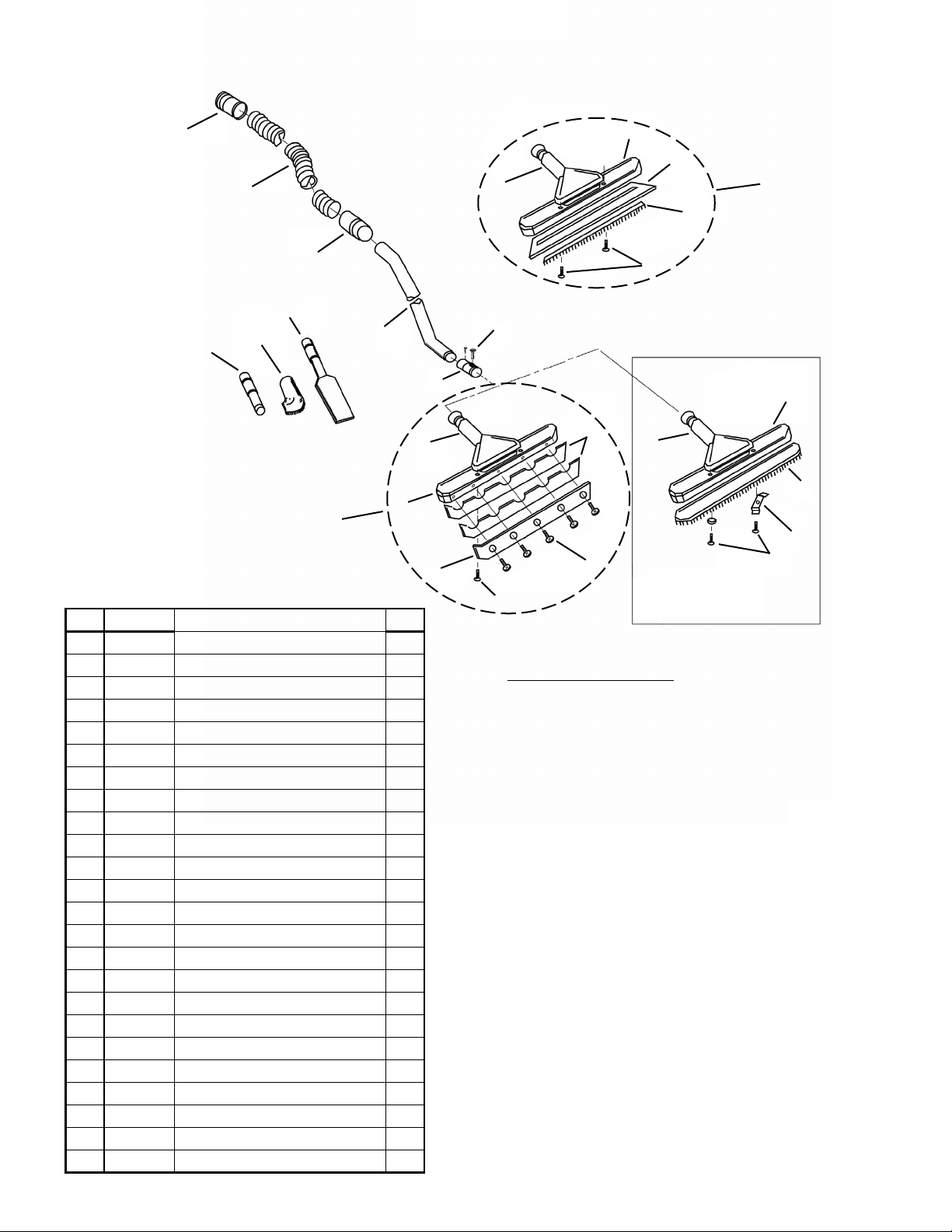
MODELS PV-12, PV-18 & PVS-18
LIMITED WARRANTY
The SSS Wet/Dry Poly Vac has been manufactured, tested and inspected in accordance with specific engineering requirements, and is
WARRANTED by the manufacturer to be free from defects in workmanship and materials.
This warranty is, however, subject to the following qualifications, conditions and limitations which are set forth to provide you and all users
of the SSS Wet/Dry Poly Vac with information concerning the duration, extent, availability and applicability of this Limited Warranty, the
procedure to be taken to obtain its performance and other information concerning the manufacturer’s warranty policy.
1. TO WHOM EXTENDED AND DURATION OF ITEMS COVERED
This warranty extends to the original consumer purchaser from the date it
was purchased and for the items and periods as follows:
Five (5) years parts, one (1) year labor - Polyethylene Tank
One (1) year parts & labor - All other components unless excluded below.
2. PARTS NOT COVERED BY WARRANTY
Certain parts of the SSS Wet/Dry Poly Vac require replacement in the or-
dinary course of use due to normal wear by reason of their characteristics.
This warranty does not cover wear parts and accessories of the machine
such as electrical cords, carbon motor brushes, floor brushes, hoses, tools,
filters, casters, wheels, etc.
3. EXCEPTIONS AND EXCLUSIONS FROM WARRANTY
The SSS Wet/Dry Poly Vac is required to be used on electric current as
indicated on the nameplate. Otherwise damage, defects, malfunctions or
other failures of the SSS Wet/Dry Poly Vac arising from use on electric
current not as indicated are excepted and excluded from this warranty.
Defects, malfunctions, failure or damage of the SSS Wet/Dry Poly Vac
caused by improper, unreasonable or negligent use or abuse while in the
possession of the consumer are likewise excluded from this warranty.
If repair is done on your SSS Wet/Dry Poly Vac by anyone other than
those below designated as authorized to perform such work without first
having obtained factory instructions, the manufacturer, at its sole option,
may determine that this warranty will not apply and that reimbursement
for such repair will not be made because of the failure to comply with such
factory specified instructions.
4. PROCEDURE TO BE TAKEN TO OBTAIN PERFORMANCE
OF WARRANTY
To secure repair of the SSS Wet/Dry Poly Vac or any warranted parts under
this warranty, the following procedure should be taken: The inoperative SSS
Wet/Dry Poly Vac or warranted parts, together with satisfactory evidence
of the purchase date, must be delivered with shipping and delivery charges
prepaid to the Dealer from whom purchased.
If you are unable to locate the Dealer, you may write or otherwise com-
municate with Triple S, 2 Executive Park Drive, Billerica, MA 01862
for instructions before repair service is performed by anyone else. In such
event Triple S will provide either the location of a closely available Triple
S Distributor Service Department or other factory instructions.
Upon compliance with the above procedure, all warranted defects will
be repaired, at no additional charge or costs to the consumer, and the
repaired product returned to the consumer, with all shipping and delivery
charges prepaid.
In following the procedures above set forth PLEASE MAKE CERTAIN
to state the Triple S model, type and serial number as shown on the name
plate of the SSS Wet/Dry Poly Vac.
REPLACEMENT
In the event of the defect, malfunction or failure of your SSS Wet/Dry Poly
Vac or any warranted part to conform with this warranty, the manufacturer
may at its sole option and own expense, replace the SSS Wet/Dry Poly Vac
or any warranted part with another new identical or reasonably equivalent
model or part in lieu of repairing the defect.
5. NO REFUND OF PURCHASE PRICE
Triple S will not, as a matter of its warranty policy, refund the consum-
er’s purchase price.
6. WARRANTY REGISTRATION CARD FOR YOUR SSS WET/
DRY POLY VAC AND REQUESTS FOR INFORMATION
Please fill out the warranty registration card accompanying your SSS
Wet/Dry Poly Vac, giving complete information as requested on the
card, and return to Triple S.
This warranty is in lieu of all other expressed or implied warranties.
This manual suits for next models
2
Table of contents
Other Triple S Vacuum Cleaner manuals

Triple S
Triple S Speedster 1000H Guide

Triple S
Triple S BPV-40 Installation and operation manual

Triple S
Triple S SC-19 Installation and operation manual

Triple S
Triple S PS-2 Guide

Triple S
Triple S SV-12 Installation and operation manual

Triple S
Triple S Panther 18C User manual

Triple S
Triple S LAV-30 Installation and operation manual

Triple S
Triple S AF9 User manual

Triple S
Triple S LAV-30 Installation and operation manual

Triple S
Triple S PRO TWIN DELUXE 14 Installation and operation manual