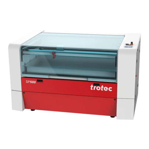
Trotec SP2000 User manual

www.troteclaser.com
SP2000
Pre-installation Guide
IV 8034_2.0_EN (01/2017)
ENGLISH

2 / 30 IV 8034_2.0_EN (01/2017)
www.troteclaser.com
Trotec Laser GmbH
Linzer Straße 156
A –4600 Wels
AUSTRIA
Trotec Laser GmbH
Freilingerstraße 99
A –4614 Marchtrenk
AUSTRIA
Tel.: +43-(0)7242-239-0
www.troteclaser.com
Technical
Changes
Technical specifications are subject to change without notice.
Trotec Laser GmbH reserves the right to improve or modify any of the products without
prior notice.
Copyright
This documentation with all illustrations is intellectual property of Trotec Laser GmbH.
The entire documentation is given to the user for personal use only. Reproduction,
translation or any distribution to third parties is not permitted without the prior consent of
Trotec Laser GmbH. Any breach of law will be prosecuted.

SP2000/Content
IV 8034_2.0_EN (01/2017) 3 / 30
www.troteclaser.com
CONTENT
1General .............................................................................................................................................. 5
1.1 Information about this manual .................................................................................................... 5
1.1.1 Complementary documentation ....................................................................................... 5
1.2 Explanation of symbols............................................................................................................... 6
2Safety................................................................................................................................................. 7
2.1 Laser classification ..................................................................................................................... 7
2.2 Responsibilities of the operator .................................................................................................. 8
3Side preparation............................................................................................................................... 9
3.1 Packaging................................................................................................................................... 9
3.1.1 Packaging Version 1 ........................................................................................................ 9
3.1.2 Packaging Version 2 ........................................................................................................ 9
3.1.3 Cooling system............................................................................................................... 10
3.1.4 Exhaust (optional) .......................................................................................................... 10
3.2 Delivery..................................................................................................................................... 10
3.2.1 Delivery state and transport ........................................................................................... 10
3.2.2 Transport inspection and reporting of defects................................................................ 11
3.2.3 Temperature and humidity ............................................................................................. 11
3.2.4 Required tools for unloading and transport.................................................................... 11
3.2.5 Transport conditions....................................................................................................... 12
3.3 Storage ..................................................................................................................................... 13
3.3.1 Temperature and humidity ............................................................................................. 13
3.3.2 Storage conditions.......................................................................................................... 13
3.4 Operating environment............................................................................................................. 14
3.4.1 Temperature and humidity ............................................................................................. 14
3.4.2 Subsoil conditions .......................................................................................................... 14
3.4.3 Environmental conditions ............................................................................................... 14
3.5 Space requirement ................................................................................................................... 15
3.5.1 Space requirement for installation.................................................................................. 15
3.5.2 Space requirement of the machine ................................................................................ 15
3.5.3 Space requirement of the cooling system...................................................................... 16
3.5.4 Machine and component layout ..................................................................................... 17
4Requirements.................................................................................................................................. 18
4.1 Supply connections................................................................................................................... 18
4.1.1 Plug type......................................................................................................................... 19
4.2 requirements of the machine.................................................................................................... 19
4.3 Water cooling system requirements......................................................................................... 20
4.3.1 Electrical requirements of the water cooling systems.................................................... 20
4.3.2 Ideal water quality .......................................................................................................... 20
4.4 Exhaust system requirements .................................................................................................. 21
4.4.1 Electrical requirements of the exhaust system............................................................... 21
4.4.2 Table and laserhead exhaust system ............................................................................ 22
4.5 Compressed air requirements .................................................................................................. 23
4.6 Computer requirements............................................................................................................ 23
5Setup and installation.................................................................................................................... 24
5.1 Required personnel .................................................................................................................. 24


SP2000
Content
4 / 30 IV 8034_2.0_EN (01/2017)
www.troteclaser.com
6Technical Data................................................................................................................................ 25
6.1 Machine dimensions and weight .............................................................................................. 25
6.1.1 Front view....................................................................................................................... 25
6.1.2 Side view........................................................................................................................ 25
6.1.3 Top view......................................................................................................................... 26
6.1.4 Maschine weight............................................................................................................. 26
6.2 Operation panel exterior dimension.......................................................................................... 27
6.2.1 Side, front and top view.................................................................................................. 27
6.3 Travelling exhaust exterior dimensions.................................................................................... 28
6.3.1 Front –and side view ...................................................................................................... 28
6.3.2 Top view......................................................................................................................... 28
6.4 Exhaust with sound-insolating enclosure (optional) ................................................................. 29
7Appendix ......................................................................................................................................... 30
7.1 Acceptance form....................................................................................................................... 30

SP2000
General
IV 8034_2.0_EN (01/2017) 5 / 30
www.troteclaser.com
1 General
1.1 Information about this manual
PLEASE READ THIS MANUAL CAREFULLY BEFORE USE
KEEP THE MANUAL FOR FURTHER CONSULTATION
This manual describes how to operate the machine properly and safely. Be sure to follow the safety
instructions given here, as well as any local accident prevention regulations and general safety
regulations applicable to the field of usage.
1.1.1 Complementary documentation
Complementary documentation can be found on the supplied DVD.
Operation Manual
SP2000_Operationmanual_EN
Software Operation Manual
Trotec JobControl®
JobControl_Operationmanual_x.x.x_Vx.x

SP2000
General
6 / 30 IV 8034_2.0_EN (01/2017)
www.troteclaser.com
1.2 Explanation of symbols
Important technical safety notes and instructions in this manual are marked with symbols. These
instructions for workplace safety must be complies with and followed. Here special attention must be
paid in order to avoid accidents, injury to persons or material damage.
DANGER
This symbol indicates information noncompliance wherewith result in death or serious
injury.
WARNING
This symbol indicates information noncompliance wherewith may result in death or
serious injury.
WARNING
This symbol warns of potentially dangerous situations related to electric voltage. Failure to
observe the safety instructions leads to risk of serious injury or death. Care is to be taken
in particular during maintenance and repair work.
WARNING
This symbol warns of potentially dangerous situations related to the laser beam. Failure to
observe the safety instructions leads to risk of serious injury.
Material damage
This symbol indicates information noncompliance wherewith may lead to material
damage, functional failures and/or machine breakdown.
Info
This symbol marks tips and information which are to be observed to ensure efficient and
failure-free operation of the machine.

SP2000
Safety
IV 8034_2.0_EN (01/2017) 7 / 30
www.troteclaser.com
2 Safety
2.1 Laser classification
The here described machine is equipped with an enclosed laser pointer and a sealed carbon dioxide
laser source that emits invisible and intense laser radiation with a wavelength of 10.6 microns.
Laser classification according to DIN EN 60825-1 "Safety of Laser Products":
- SP2000 laser machine Class 2 (US: Class II) due to the key safety devices and
enclosed laser pointer
- Laser source Class 4 (US: Class IV)
- Enclosed laser pointer Class 2 (US: Class II)
WARNING
Laser radiation of Class 2 (US: class II)
Lasers of Class 2 (US: Class II) are safe, but can cause irritation of the eyes if the natural
avoidance reaction (staring into the beam deliberately) or eyelid closure reflex is suppressed.
- Do not suppress the eyelid closure reflex.
- Do not stare directly into the beam.
- Close eyes, turn away.
- Never look at the laser beam directly with an optical instrument, e.g. a lens.
WARNING
Laser radiation of Class 4 (US: class IV)
Exposure to laser radiation of Class 4 (US: Class IV) can cause injury to the eyes and skin.
- The skin and eyes must not be exposed to direct or reflected or scattered radiation.
- Wear suitable laser safety protection glasses.
- When dealing with Class 4 (US: Class IV) laser machines, it is necessary to appoint a
trained laser safety officer to evaluate potential hazards and to ensure that appropriate
control measures are implemented.
It is the responsibility of the operator to comply with the national official and statutory
regulations for the operation of a class 4 (US: class IV) laser system or laser system with
a build in laser source of class 4 (US: class IV).

SP2000
Safety
8 / 30 IV 8034_2.0_EN (01/2017)
www.troteclaser.com
2.2 Responsibilities of the operator
The operator has the following responsibilities:
- It is the responsibility of the operator to comply with the national official and statutory
regulations for the operation of a class 4 (US: class IV) laser system or laser system with a
build in laser source of class 4 (US: class IV).
- In addition to the safety notes and instructions stated in this manual, consider and observe the
local accident prevention regulations and general safety regulations that apply at the operation
site of the machine.
- A CO2fire extinguisher must always be at hand, as the laser beam can ignite flammable
materials.
- If the machine is used industrially, the operator is subject to the legal obligations concerning
industrial safety.
- All personnel involved in installation, set-up, operation, maintenance and repair of the machine
must have read and understood this Manual and in particular the “Safety” section. The
personnel must be trained and informed about all the functions and potential dangers of the
machine.
- The user is recommended to prepare company internal instructions considering the
occupational qualifications of the personnel employed in each case, and the receipt of the
instruction/Manual or the participation in the introduction/training should in each case be
acknowledged in writing.
- Keep the manual in the immediate vicinity of the machine so that it is accessible at all times to
all persons working on or with the machine.
- Authority for the individual activities relating to the application of the machine (e.g. installation,
operation, maintenance and cleaning) must be clearly defined and observed, so that no
unclear competencies result under the aspect of safety. This applies in particular to work to be
performed on the electrical equipment that may only be performed by qualified specialists.
- Maintenance and repair work as specified in the present manual must be carried out regularly.
- For all activities concerning installation, set-up, start-up, operation, modifications of conditions
and methods of operation, maintenance, inspection and repair, the switch-off procedures that
may be provided in the Manual must be observed.
- Provide appropriate personal protection equipment (e.g. protective goggles according to
wavelength and laser power).
- The operator is responsible for the safety-related state of the machine.
- Do not store any flammable materials in the working area or in the immediate vicinity of the
device. Particularly, residues of processed materials have to be removed to prevent any fire
hazard.
- The operator must ensure cleanliness and accessibility at and around the machine by
corresponding instructions and controls.

SP2000
Side preparation
IV 8034_2.0_EN (01/2017) 9 / 30
www.troteclaser.com
3 Side preparation
3.1 Packaging
3.1.1 Packaging Version 1
No
Machine parts
Packaging
(L x W x H) /mm (inch)
Weight /
kg (pound)
Type
1
Machine with cover
3340 x 2620 x 1220
(131.5 x 103.1 x 48)
2500
(5511.6)
wooden crate
2
Operating console
990 x 810 x 1425
(38.9 x 31.8 x 56.1)
200
(440.9)
wooden crate
3
Laser tube
1470 x 400 x 500
(57.8 x 15.7 x 19.7)
250
(551)
wooden crate
4
Table system (for each table)
1890 x 965 x 690
(74.4 x 37.9 x 27.2)
250
(551)
wooden crate
5
Cooling system
800 x 1000 x 1100
(31.5 x 39.4 x 43.3)
150
(330,7)
wooden crate
6
Traveling exhaust
600 x 800 x 144
(23.6 x 31.5 x 5.7)
50
(110,2)
pallet
3.1.2 Packaging Version 2
No
Machine parts
Packaging
(L x W x H) /mm (inch)
Weight /
kg (pound)
Type
1
Machine and x-axis
3190 x 2270 x 1510
(125.6 x 89.4 x 59.4)
1360
(53.5)
wooden crate
2
Cover and traveling exhaust
3390 x 1160 x 955
(133.5 x 45.7 x 37.6)
575
(22.7)
wooden crate
2
Laser tube
1560 x 540 x 680
(61.4 x 21.3 x 26.8)
145
(5.7)
wooden crate
3
Table system (for each table)
1890 x 965 x 690
(74.4 x 38 x 27.2)
200
(7.9)
wooden crate
4
Operating console
990 x 810 x 1425
(39 x 31.9 x 56.1)
150
(6)
wooden crate

SP2000
Side preparation
10 / 30 IV 8034_2.0_EN (01/2017)
www.troteclaser.com
3.1.3 Cooling system
No
Cooling system
(according laser
power)
Dimension (L x W x H) /
mm (inch)
Weight /
kg (pound)
Weight /
(parts)
kg (pound)
Type
1
400 W
1000 x 800 x 600
(39.37 x 31.49 x 23.6)
220
(485)
190
(419)
palette /
carton box
2
200 W
760 x 610 x 500
(29.92 x 24 x 19.68)
110
(242.5)
90
(198.4)
palette /
carton box
3
100 W
710 x 545 x 455
(27.95 x 21.45 x 17.91)
85
(187.4)
65
(143.3)
palette /
carton box
3.1.4 Exhaust (optional)
No
Machine
Dimension (L x W x H) /
mm (inch)
Weight /
kg
Weight /
(machine)
kg (pound)
Type
1
VENT 3000 Set
(with sound-
insulating enclo-
sure)
1200 x 800 x 700
(47.24 x 31.49 x 27.56)
212
(467.4)
170
(375)
transport
box
2
Piping
1200 x 800 x 1450
(47.24 x 31.49 x 57.08)
84
(185.2)
47
(103.6)
transport
box
3.2 Delivery
3.2.1 Delivery state and transport
Unless otherwise agreed, the machine/machine parts and additional accessories get delivered in
wooden crates.
Store the machine/machine parts sealed in the original packaging and shortly before installation
transport the sealed packaging units to the production site.
Unpacking the machine/machine parts is carried out by a Trotec technician at the productions site.
If it is not possible to transport the sealed packaging units to the production site due to confined space
conditions, a Trotec technician will unpack the machine parts at the storage place and will then
transport the parts to the production site.

SP2000
Side preparation
IV 8034_2.0_EN (01/2017) 11 / 30
www.troteclaser.com
3.2.2 Transport inspection and reporting of defects
Upon receipt, immediately inspect the delivery to ensure that it is complete and has not suffered any
damage. If any transport damage is visible, do not accept the delivery, or accept it only with
reservation. Record the scope of the damage on the transport documents/delivery note. Initiate the
complaint process. For all defects that are not discovered upon delivery, be sure to report them as
soon as they are detected, since damage claims must be filed within a certain period, as mandated by
law.
3.2.3 Temperature and humidity
Ambient temperature for
transportation
-10 °C to 40 °C (-50 °F to 104 °F)
Humidity
max. 85% (non-condensing)
3.2.4 Required tools for unloading and transport
Unloading the packaged
machine parts
Transport the unpacked
machine parts
Type
forklift
pallet truck
Weight
weight ≥ 1.5 t
weight ≤ 1.5 t
Fork extension
approx.
2 m (78.74 inch)
approx.
2 m (78.74 inch)

SP2000
Side preparation
12 / 30 IV 8034_2.0_EN (01/2017)
www.troteclaser.com
3.2.5 Transport conditions
Conditions:
- Observe the packaging symbols:
Symbol
Meaning according to ISO/DIN
Symbol
Meaning according to ISO/DIN
vor Nässe schützen/
keep dry
oben/
this way up
zerbrechliches Packgut/
fragile, handle with care
nicht stapeln/
do not stack
- Note the shock watch sign

SP2000
Side preparation
IV 8034_2.0_EN (01/2017) 13 / 30
www.troteclaser.com
3.3 Storage
3.3.1 Temperature and humidity
Storage temperature:
0 °C to 30 °C (32 °F to 86 °F)
Relative humidity:
max. 60%
3.3.2 Storage conditions
Conditions:
- Keep the machine sealed in its original packaging until it is assembled/installed.
- Do not stack the wooden crates or boxes.
- Keep the storage location dry, free of dust, caustic materials, vapors and combustible
materials.
- Store in a storage room or packaged with adequate weather protection.
- Avoid exposure of the machine to shocks or vibrations.
- Avoid extreme temperature fluctuations.
- Take particular care when packing away electronic components.
- Apply a coat of oil to all bare-metal machine parts, when storing for a longer period.
- Regularly check the overall condition of all parts and of the packaging.

SP2000
Side preparation
14 / 30 IV 8034_2.0_EN (01/2017)
www.troteclaser.com
3.4 Operating environment
3.4.1 Temperature and humidity
Operating temperature:
15 °C to 25 °C (59 °F to 77 °F)
Air humidity:
40% –70% (non-condensing)
3.4.2 Subsoil conditions
Conditions:
- Planarity ±5 mm (±0.1969 inches)
- Solid, firm and vibration-free soil
- Easy-care and clean floor
- Bearing capacity of the subsoil ≥1000 kg/m2/ 10 kN/m2(208.85 psf)
- Machine point load 500kg/m² / 5 kN/m2(102.4 psf)
- Monolithic subsoil conditions underneath the laser machine
- No special substrate preparation required
3.4.3 Environmental conditions
Conditions:
- Provide sufficient illumination at the workplace
- Ensure a dust-free environment (II° according to IEC60947-1)
- Shielding from EMC
- Freedom of interfering electrical installations, hoses and pipe lines
- Power supply free of fluctuations

SP2000
Side preparation
IV 8034_2.0_EN (01/2017) 15 / 30
www.troteclaser.com
3.5 Space requirement
Ensure there is shielding or sufficient clearance to or from the wall and neighboring objects.
3.5.1 Space requirement for installation
Space required
Area
Total
60m² (645 square feet)
3.5.2 Space requirement of the machine
Space required
Area
Maschine incl. safety distance (excluding
operating panel, exhaust and loading/unloading
area)
28 m² (302 square feet)

SP2000
Side preparation
16 / 30 IV 8034_2.0_EN (01/2017)
www.troteclaser.com
3.5.3 Space requirement of the cooling system
Objects
Distance
Laser
1 m (39.4 in)
Neighboring objects/wall
0,5 m (19.68 in)
3.5.3.1 Dimensions of the water cooling systems
Laser power
60 W
WC *
100 W
WC *
200 W
WC *
400 W
WC *
L x B x H [mm]
(L x B x H [inch])
710 x 545 x 455
(27.9 x 21.5 x 17.9)
710 x 545 x 455
(27.9 x 21.5 x 17.9)
760 x 610 x 500
(29.9 x 24.0 x 19.7)
715 x 715 x 1545
(28.2 x 28.2 x 60.8)
* WC = Wassergekühlt

SP2000
Side preparation
IV 8034_2.0_EN (01/2017) 17 / 30
www.troteclaser.com
3.5.4 Machine and component layout
Ensure there is shielding or sufficient clearance to or from the wall and neighboring objects.
Layout
Cooling system
Note cable length of 4 m.
Operation panel
Note cable length of 2 m.
Due to the length of the console cable set the console can
only be placed as shown in the graph below.
Exhaust
HH

SP2000
Requirements
18 / 30 IV 8034_2.0_EN (01/2017)
www.troteclaser.com
4 Requirements
4.1 Supply connections
Abbr.
Connection
Dimension
Cable/hose
Info
Volume
P
Power supply
Flexible
cable
3 m
See chapter
"Electrical
requirement"
I
Operating console interface
Flexible
cables
(compiled)
2 m
A
Compressed air
(3 one hand universal quick-
lock coupling included)
Couplings for
hose
Ø 6 mm
Ø 9 mm
Ø 10 mm
Flexible
hose)*
-
>240 l/min at
6 bar
EH
Exhaust laserhead
Inner Ø 76 mm
(laser side)
Outer Ø 80 mm
(exhaust side)
Flexible
hose
3 m
100 m³/h at
4450 Pa
ET
Exhaust table
Outer Ø 200 mm
(both sides)
Flexible
hose
3 m
2500 m³/h at
800 Pa
C
Cooling system
(not included in the drawing -can be
placed anywhere but not higher as
machine level)
½" < 200W
1" 200-400W
Flexible
hose
4 m
Depending on
cooling system
* Item NOT included in scope of delivery, OPTIONAL
P
I
A
EH
HH
ET

SP2000
Requirements
IV 8034_2.0_EN (01/2017) 19 / 30
www.troteclaser.com
4.1.1 Plug type
1 Phase
3 Phase
4.2 requirements of the machine
Laser power
60 W
WC *
100 W
WC *
200 W
WC *
400 W
WC *
Voltage
380/400 VAC
3 phase
380/400 VAC
3 phase
380/400 VAC
3 phase
380/400 VAC
3 phase
Fuse
3 x 16A (slow-blow)
3 x 16A (slow-blow)
3 x 16A (slow-blow)
3 x 16A (slow-blow)
Power
consumption
1600 W
3100 W
4500 W
8400 W
Ground fault
circuit
interrupter
necessary
necessary
necessary
necessary
* WC = water cooled
Inadequate or inappropriate power sources can lead to machine damage and are not
covered by any liability.
Verify that the electrical outlet is capable of providing the proper voltage, frequency and
amperage required by the laser machine described in this manual.
Electrical noise, unstable power supply as well as voltage spikes in power supply can
cause interference and possible damage to the electronics of the laser machine.
Use an individual circuit for the laser machine and the PC and an individual circuit for the
exhaust system. Install your computer on the same circuit as the laser machine to
prevent electromagnetic interactions.
Furthermore it is highly recommended that you use a surge suppression plug to protect
your computer equipment.
If electrical power fluctuations, brownouts or power outages are a problem in your area,
an electrical line stabilizer, UPS (Uninterruptible Power Supply) or backup generator are
required. When installing any of these devices, ensure that they meet the electrical
requirements of the laser machine.

SP2000
Requirements
20 / 30 IV 8034_2.0_EN (01/2017)
www.troteclaser.com
4.3 Water cooling system requirements
4.3.1 Electrical requirements of the water cooling systems
Laser power
60 W
WC *
100 W
WC *
200 W
WC *
400 W
WC *
EU
US
EU
US
EU
US
EU
US
Voltage
230V
-
230V
115V
230V
230V
400V
400V
Fuse
16A
(slow-
blow)
-
16A
(slow-
blow)
16A
(slow-
blow)
16A
(slow-
blow)
16A
(slow-
blow)
16A
(slow-
blow)
16A
(slow-
blow)
Power
consumption
1900 W
-
1900 W
1900 W
2700 W
2700 W
6600 W
6600 W
Frequency
50/60Hz
-
50/60Hz
60Hz
50Hz
60HZ
50/60Hz
50/60Hz
* WC = Wassergekühlt
4.3.2 Ideal water quality
pH-value:
7-9
Alkalinity (°dH):
<1
Conductivity:
<300 µS/cm
Chloride content:
<20 mg/L
Hardness (°dH):
7,5-8,5
Organic germs:
<1000 KBE/ml
Other manuals for SP2000
1
Table of contents
Other Trotec Cutter manuals

Trotec
Trotec SpeedMaker 300 User manual

Trotec
Trotec Speedy 500 User manual

Trotec
Trotec Q500 User manual

Trotec
Trotec SP500 User manual

Trotec
Trotec SpeedMarker 300 User manual

Trotec
Trotec Speedy 500 User manual

Trotec
Trotec Rayjet 300 User manual

Trotec
Trotec SP500 User manual

Trotec
Trotec SP1500 User manual

Trotec
Trotec Q400 User manual
Popular Cutter manuals by other brands

Caslon
Caslon ProCrease Operation and maintenance manual

Makita
Makita CC301DZJ instruction manual

Milwaukee
Milwaukee C12 PC Operator's manual

Wolfcraft
Wolfcraft TC 710 PM Translation of the original operating instructions

Bosch
Bosch GWS 24-300 PROFESSIONAL operating instructions

UCHIDA
UCHIDA AEROCUT G2 Operation manual