Trotec SP1500 User manual

SP1500 Operation Manual

2 / 53 8018_SP1500 V2.2_EN (03/2018)
Copyright© by Trotec Laser GmbH
All rights reserved.
Anyone who reproduces, copies or distributes this document, or parts of it, without the approval
of Trotec Laser GmbH is subject to prosecution.
We do not assume liability for any errors contained in this documentation.
We reserve the right to make technical changes.
Trotec Laser GmbH
Linzer Strasse 156,
A-4600 Wels, OÖ.
AUSTRIA
Tel.: +43-(0)7242-239-0
Fax: +43-(0)7242-239-7380
trotec@troteclaser.com
www.troteclaser.com

3 / 53 8018_SP1500 V2.2_EN (03/2018)
Table of Contents
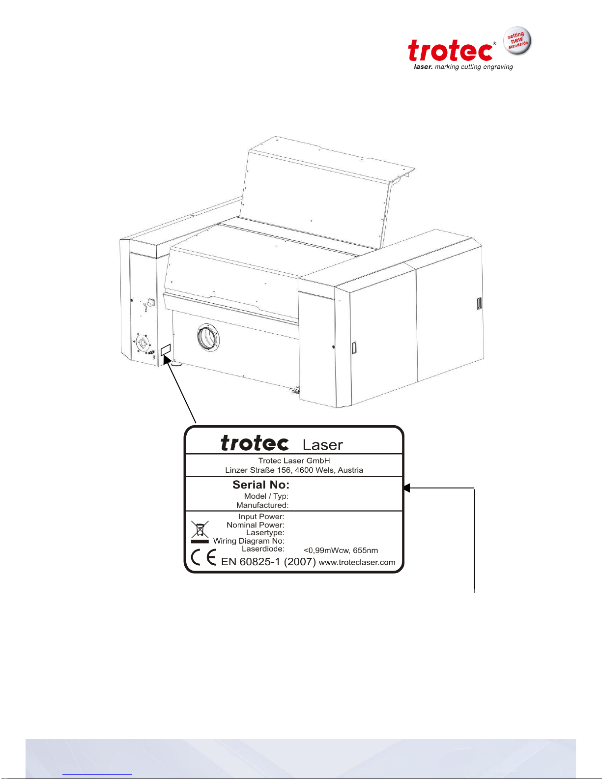
1 Manufacturing label........................................................................................................5
2 Product Components .....................................................................................................6
3 Preface.............................................................................................................................7
3.1 General .................................................................................................................................7
3.2 Product Tracking ...................................................................................................................8
4 Technical Data ................................................................................................................9
4.1 General Description...............................................................................................................9
4.2 Intended Use.........................................................................................................................9
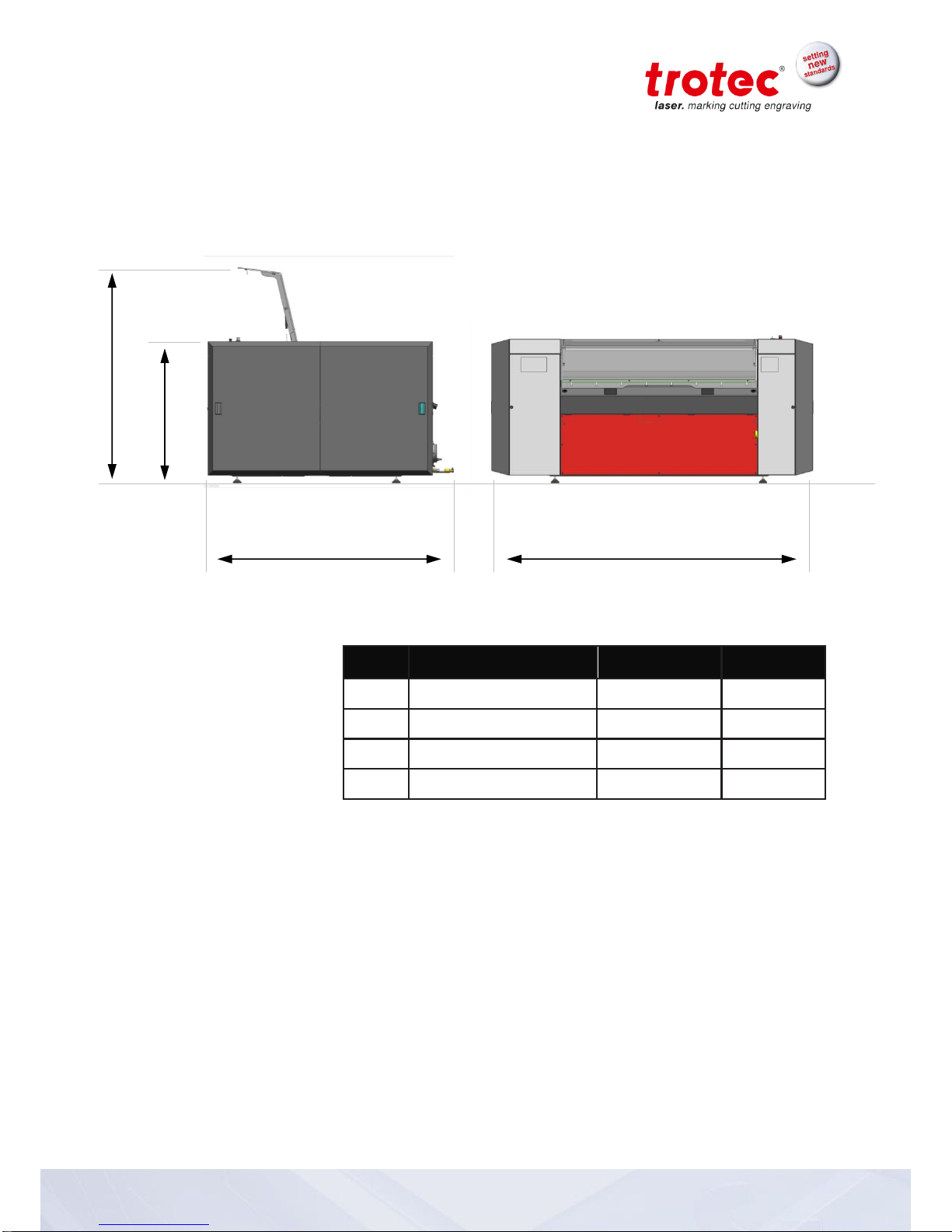
4.3 Dimensions..........................................................................................................................10
4.4 Mechanical Design..............................................................................................................11
4.5 Control System....................................................................................................................11
4.6 Laser Tubes ........................................................................................................................11
4.7 Laser Safety........................................................................................................................12
4.8 Ambient Conditions .............................................................................................................12
4.9 Options................................................................................................................................12
4.10 Electrical Connection.........................................................................................................13
4.10.1 Electrical connection for laser system .........................................................................13
4.10.2 Electrical connection for water cooling (option) ...........................................................13
4.11 Materials............................................................................................................................14
5 Safety.............................................................................................................................15
5.1 Safety Instructions...............................................................................................................15
1.1 Intended user group.........................................................................................................15
1.2 Operating instructions / Safety equipment........................................................................15
5.2 General Safety Instructions .................................................................................................16
2.1 General............................................................................................................................16
2.2 Laser................................................................................................................................19
2.3 Transport .........................................................................................................................20
5.3 Secondary Risks .................................................................................................................21
3.1 General............................................................................................................................21
3.2 Crushing hazard...............................................................................................................21
5.4 Signage...............................................................................................................................22
6 Transport - Storage - Setup .........................................................................................24
6.1 Forklift transport ..................................................................................................................24
6.2 Shipping conditions .............................................................................................................26
6.3 Unloading, inspection and damage reporting.......................................................................26
6.4 Storage conditions...............................................................................................................26
6.5 Storage Location.................................................................................................................26
6.6 Installation Site....................................................................................................................27
6.7 Space Requirements...........................................................................................................27
6.8 Necessary Feed Lines.........................................................................................................27
6.9 Setup...................................................................................................................................28
6.10 Connections ......................................................................................................................29
6.10.1 Cooling System...........................................................................................................30
7 Machine view.................................................................................................................31
8 Operation.......................................................................................................................32
8.1 Key pad –Overview ............................................................................................................32

4 / 53 8018_SP1500 V2.2_EN (03/2018)
8.2 Key pad –Description .........................................................................................................33
8.3 Workpiece Removal Door....................................................................................................36
8.4 Tables .................................................................................................................................37
8.4.1 Cutting Table (Standard Table).....................................................................................37
8.4.2 Vacuum Table...............................................................................................................37
8.5 Operation ............................................................................................................................38
8.6 Changing the lens................................................................................................................39
9 Maintenance..................................................................................................................44
9.1 Cleaning optics on the Laser Head......................................................................................44
9.2 Cleaning the Mirrors............................................................................................................45
9.3 Cleaning the Exhaust hose connector .................................................................................46
9.4 Maintenance plan................................................................................................................47
10 Appendix .....................................................................................................................48
10.1 EU –Declaration of conformity..........................................................................................48
10.2 Acceptance report .............................................................................................................49
10.3 Acceptance report .............................................................................................................50
10.4 Response Form.................................................................................................................51
10.5 How to create a Service File..............................................................................................52

5 / 53 8018_SP1500 V2.2_EN (03/2018)
1 Manufacturing label
You find the manufacturing label with the CE-sign on the back side of the machine.
Enter the serial number, model and year of manufacture from the manufacturing label here.
This information is important for troubleshooting problems with the product and for ordering
replacement parts.

6 / 53 8018_SP1500 V2.2_EN (03/2018)
2 Product Components
Lenses 2.5“ / 5“
(7.5“ optional)
RS232-cable (TroCAM / i-Cut)
(7.5“ optional)

7 / 53 8018_SP1500 V2.2_EN (03/2018)
3 Preface
3.1 General
This operating manual is intended to simplify the following for you:
Learning about the machine, and
Utilizing the machine’s capabilities according to its
intended use.
The operating manual contains important notes on how to operate
the machine:
Safely,
Properly, and
Economically
Following the operating instructions helps you to:
Avoid hazards and risks,
Minimize repair costs and downtimes, and
Increase the reliability and service life of your machine.

8 / 53 8018_SP1500 V2.2_EN (03/2018)
3.2 Product Tracking
We have a legal duty to track our products after delivery to our
customers.
In particular, this relates to:
Recurring faults in functions
Anything that is unclear, e.g. in operation, maintenance
or instructions
Any accidents that occur
Other unusual observations
Recommendations for improvement, requests
This information serves as a basis for potential corrections and/or
changes to the product, and it is therefore of great interest to us.
We request that you inform us of any such events and offer us
your recommendations. This is the only way that we can improve
our products as necessary, and to make them as safe and reliable
as possible.

9 / 53 8018_SP1500 V2.2_EN (03/2018)
4 Technical Data
4.1 General Description
All electronic components are integrated in the machine.
All necessary connections are made on the back side of the SP1500.
Controls for the SP1500 are located on the keypad.
The SP1500 is equipped with an interlock safety system. When
the interlock is activated, only setup tasks can be performed on the
SP1500.
The machine has a manual table changing system that enables use of the
optimal table for specific jobs.
4.2 Intended Use
The Trotec SP1500 is designed for engraving and cutting of the
materials listed in this document.

10 / 53 8018_SP1500 V2.2_EN (03/2018)
4.3 Dimensions
Weight –depends on product model ............... 1200 - 1300kg
(2646 - 2867 lbs)
Item
Description
Dimension
Units
A
Length
2829 (112)
mm (inch)
B
Width
2197 (87)
mm (inch)
C
Height, closed
1293 (51)
mm (inch)
D
Height, open
1950 (77)
mm (inch)
C
D
B
A

11 / 53 8018_SP1500 V2.2_EN (03/2018)
4.4 Mechanical Design
Working area
1500 x 1250 mm (59 x 49 in)
Feed area
1700 x 1600 mm (66 x 62 in)
Max. height of work piece
30 / 53 / 75 mm (1.18 / 2.08 / 2.95 in)
(3 work table levels)
185 mm (7.28 in) without work table
(flatness cannot be guaranteed without work table)
Speed of motion system
165 cm/s (65 in/sec)
Acceleration
9,55 m/s² (375 in/sec²)
Motor
Brushless DC servomotor
Encoder
Increment measuring system
Lenses
2,5“ and 5.0” (Standard), 7.5” (optional)
Lenses and all reflective mirrors are air-flushed and
therefore protected from soiling (preinstalled air pump)
Max. area load of workpiece
table
25 kg (55 lbs) over entire working area
Precision
±0,1 mm (±0.004 inch) over entire working
area
(depends on material)
Repeatability
< ±15 µm
(< ±0.00059 inch)
4.5 Control System
Laser power
Adjustable 0 –100% (Typically 10-100%)
Hardware Interface
USB, RS-232 (RS-232 mandatory for TroCAM and i-Cut)
Software Interface
ASCII, HPGL, Trotec Protocol
4.6 Laser Tubes
Laser tubes
Sealed off CO2 laser, maintenance free,
Laser power of 60-400W
Wavelength
10,6 µm

12 / 53 8018_SP1500 V2.2_EN (03/2018)
4.7 Laser Safety
Laser class
CDRH Laser Safety; CE tested
Laser class 2
Interlock
Dual interlock safety system
4.8 Ambient Conditions
Prescribed ambient temperature of +15° to +25°C (+59° to +77°F)
Humidity of 40% to max. 70%, no condensation,
dust-free environment (2nd degree per IEC60947-1)
4.9 Options
CCD-camera
Registration marks and compensation system „i-Cut“;
max. working area: 1100 x 700 mm (43 x 27.5 in)
Gas-Kit (for compressed air
respectively process gas)
Considered for control of compressed air and process
gas (free of mechanical dust, water and oil) max. flow
rate 150 l/min (40 gpm) with max. 10 bar (145 psi) max.
limit 4 bar on working head push fitting connection with
out diameter) connection on the machine with hose out
diameter of 6mm (0.23 in) resp. standard fitting for
compressed air.
Vacuum table
Strong vacuum effect for thin or corrugated materials
(3500 m³/h at 500 Pa)
TroCAM
(refer to TroCAM brochure)
CAD / CAM software for perfect cutting results;
inclusively nesting-function, lead-in/lead-out, tool paths
Extraction System lead /follow-
up time
Lead- and follow-up time fully adjustable

13 / 53 8018_SP1500 V2.2_EN (03/2018)
4.10 Electrical Connection
4.10.1 Electrical connection for laser system
Laserpower
60 W
100 W
200 W
400 W
Voltage
208/230 V,
1 phase
208/230 V,
1 phase
380/400 V,
3 phases
380/400 V,
3 phases
Fuse
16 A, slow
20 A, slow
3 x 20 A, slow
3 x 25 A, slow
Frequency
50/60 Hz
50/60 Hz
50/60 Hz
50/60 Hz
Phases
L, N, PE
L , N, PE
L1, L2, L3, N, PE
L1,L2,L3,N, PE
Power
2,6 kW
3,5 kW
5,5 kW
9,5 kW
4.10.2 Electrical connection for water cooling (option)
EU
Laserpower
60 W
100 W
200 W
400 W
Required refrigerating capacity [W]
500
2300
4000
8000
Chiller type
Chilly 08-S
Chilly 25-S
Chilly 45-S
CWK 90-S
Refrigerating capacity [W]
890
2400
5300
9500
Rate of flow l/min
7,2
10
16
30
Pressure in bar
2,9
2,7
3,5
3,4
Supply voltage
1x230V
50/60Hz
1x230V
50/60Hz
1x230V
50Hz
3x400V
50/60Hz
Power Requirement
900
1800
3000
5900
Supply voltage
L, N, PE
L, N, PE
L, N, PE
L1, L2, L3,
N, PE
US
Laserpower
60 W
100 W
200 W
400 W
Required refrigerating capacity [W]
500
2300
4000
8000
Chiller type
Chilly 08-S
Chilly 25-S
Chilly 35-S
CWK 90-S
Refrigerating capacity [W]
890
2400
4500
11000
Rate of flow l/min
8
10
15,2
36
Pressure in bar
3,7
3,5
3,7
4,8
Supply voltage
1x115V
60Hz
1x115V
60Hz
1x230V
50/60Hz
3x400V
50/60Hz
Power Requirement
900
1800
3000
5900
Supply voltage
L, N, PE
L, N, PE
L, N, PE
L1, L2, L3,N,
PE

14 / 53 8018_SP1500 V2.2_EN (03/2018)
4.11 Materials
Caution when processing conductive materials (carbon fibers,…)! Conductive
dust or particles in the ambient air might damage electrical components and lead
to short circuits.
Bear in mind that those defects are NOT warranted.
Material
Engraving
Cutting
Marking
Acrylic
●
●
Painted metal
●
Delrin
●
●
Stainless steel (with Thermark)
●
Anodized aluminum
●
Veneer
●
●
Handicrafts
●
●
Glass
●
Wood
●
●
Gum rubber
●
●
Ceramic
●
●
Cork
●
●
Plastics
●
●
Laser rubber
●
Leather
●
●
MDF
●
Melamine
●
●
Micro porous rubber
●
●
Paper
●
●
Polyester
●
●
Stone
●
PC (Polycarbonate)
●
●
Other materials only with written approval by Trotec
The following materials are not recommended for processing:
Polyurethane PUR, Polyvinyl chloride PVC, Polyvinyl butyral PVB, Polytetrafluorethylene PTFE
and materials containing epoxy or phenolic resins
Caution:
Trotec assumes no responsibility for any consequences of laser processing in any
application such as medical or pharmaceutical applications.

15 / 53 8018_SP1500 V2.2_EN (03/2018)
5 Safety
5.1 Safety Instructions
Operating personnel must read and understand the operating instructions, and especially the
“Safety” chapter, before operating the equipment. We recommend that the operator create internal
instructional documentation for equipment safety and operation and to acknowledge receipt of
these instructions/operating manual and participation in training/education in writing (see
documents in the Appendices)
1.1 Intended user group
The machine may only be operated by authorized persons.
Authorities must be clearly defined and observed, so that no unclear competencies result under the
aspect of safety. This applies in particular to work performed on the electrical equipment that may
only be performed by specially trained professionals.
Activity
Intended group of users
Control/operation
Trained personnel
Other activities
(e.g. error correction, maintenance)
Specially trained personnel or
hired tradesmen
1.2 Operating instructions / Safety equipment
The safety zone is defined by the operator. Instructions and guidelines must be observed and
followed!
Top view
No.
Description
1
EMERGENCY-OFF pushbutton
2
Key switch
3
ON-OFF switch
4
Safety covers
1
2
4
3

16 / 53 8018_SP1500 V2.2_EN (03/2018)
5.2 General Safety Instructions
2.1 General
Hazard due to improper use of the machine!
Improper use may lead to hazards and bodily injury and damage to assets.
Prohibit or prevent improper use.
Hazard due to disregard of safety instructions!
Improper activities at the machine may lead to death, bodily injury and/or damage
to the machine.
Before startup read and observe the operating manual and safety
instructions!
Hazard due to faulty behavior by untrained persons!
Improper activities at the machine may lead to death, bodily injury and/or damage
to the machine.
Inform personnel about machine functions and potential risks and
record this in the training record.
Observe legal regulations related to operation of machines and
accident prevention regulations.
Hazard due to poor lighting, poor housekeeping and moisture!
Shadows, reflections and poor housekeeping increase the risk of an accident.
Light the work area well, and always keep it clean and dry.
Hazard due to missing, defective or bypassed safety equipment or machine
parts!
Nonfunctioning or missing safety equipment or machine parts may lead to death,
bodily injury and/or damage to the machine.
Carefully check safety equipment and machine parts for proper
operation.
In case of a functional fault or defect, immediately take prescribed
actions to correct the problem.
Hazard due to operator error (especially in setup mode)!
Adjustment and control with insufficient knowledge of the machine may lead to
death, bodily injury and/or damage to the machine.
Before startup read and observe the operating manual and safety
instructions!
Hazard due to unsupervised operation of the machine!
Unsupervised operation may lead to fire resulting in death, bodily injury and/or
damage to the machine.
Never operate the machine without supervision!

17 / 53 8018_SP1500 V2.2_EN (03/2018)
Hazard due to reckless actions!
Reckless actions may lead to death, bodily injury and/or damage to the machine.
Make sure that no personnel remain in the hazardous area or at the
machine.
Do not leave any foreign objects in the machine (tools, etc.).
Hazard due to operator error by unauthorized persons!
Adjustment and control of the machine by persons with inadequate knowledge of
machine operation may lead to death, bodily injury and/or damage to the
machine.
Never inadvertently actuate the machine.
Turn the main switch off when the machine is not being used.
Hazard during faulty work process!
Deviations in machine processing and work results may be an indication of
hazardous conditions (jammed product, loose guides, etc.).
Observe machine movements for proper operation and check work
results on a regular basis.
In case of deviations, initiate prescribed actions.
Hazard due to premature actuation!
Premature actuation of the machine may lead to death, bodily injury and/or
damage to the machine.
Do not reach into hazardous areas until you have turned off the
main switch and placed a service sign on it.
Hazard due to inadequate cleaning or functional checks!
Inadequate cleaning or functional checks result in machine damage.
Accumulation of dirt could impair mechanical functions.
Regularly check machine and connection lines for damage and
wear. In case of damage, immediately initiate prescribed actions.
Keep machine, handles and switches free of oil, grease, dirt and
moisture.
Hazard due to unsuitable tools!
The use of improper tools could result in a risk of bodily damage and/or damage
to the machine. Poor housekeeping leads to elevated accident risk.
Use proper tools for maintenance jobs.

18 / 53 8018_SP1500 V2.2_EN (03/2018)
Hazard due to missing machine signage!
The risk of machine operator error results from making incorrect assumptions.
Replace missing machine signage.
Hazard due to fault that cannot be corrected!
A fault that cannot be corrected may lead to injury and/or damage to the
machine.
Turn off the machine and call customer service!
Hazard due to improper disposal (waste, production materials)!
Improper disposal of waste materials can lead to environmental damage.
Recycle recyclable materials in separated and clean state. Dispose
of waste in accordance with applicable legal regulations.
Hazard due to inferior replacement parts or parts from other companies!
The use of inferior replacement parts or parts from other companies impairs
machine safety and invalidates the supplied Conformity Declaration (CE).
Replace wear parts or damaged machine, safety or electrical
components with original replacement parts. Only use the
accessories or auxiliary devices identified in the operating manual.
Hazard due to unsuitable work clothing or lack of protective equipment!
Risk of injury due to catching on machine parts, falling loads, inhalation of dust
particles
and noise.
Wear suitable work clothing.
Wear safety glasses.
Wear hearing protection (mandatory for noise levels >85 dB(A))

19 / 53 8018_SP1500 V2.2_EN (03/2018)
2.2 Laser
The machine is:
- Safety class 2
Hazard due to laser radiation without protective measures!
Lack of protective measures can result in:
- Burns on the corneas of the eyes,
- Skin burns, and
- Fire hazard for clothing
Never operate machine without protective equipment
Unapproved modification or disassembly of the laser is prohibited
Never manipulate the laser unit
Do not bypass the interlock system
Hazard in processing unapproved material!
Processing of materials not listed and approved in this operating manual is
prohibited.
Processing medical technology and pharmaceutical products!
Trotec assumes no responsibility for any consequences or the suitability of laser
processing for any applications, especially those in the medical technology or
pharmaceutical fields.
Hazard when working with the cutting table!
If not all of the partition plates are used in the cutting table, there is a risk of fire
due to reflection of the laser beam.
Insert anti-reflective material beneath the partition plates.

20 / 53 8018_SP1500 V2.2_EN (03/2018)
2.3 Transport
Hazard of loads impacting persons or objects!
Falling, tipping or sliding loads may lead to death, bodily injury and/or damage to
the machine.
Never let loads impact persons.
Set up unloading station before lifting loads. Avoid unnecessarily
long periods of lifting.
Do not lift loads until you have a clear view of the travel route.
Choose travel routes that are as unobstructed as possible.
Hazard due to lifting equipment operator error by untrained personnel!
Improper operation of lifting equipment may lead to death, bodily injury and/or
damage to the machine.
Operation of lifting equipment only by trained personnel.
Wear protective helmet, safety shoes and gloves.
Table of contents
Other Trotec Cutter manuals

Trotec
Trotec Q500 User manual

Trotec
Trotec Speedy 500 User manual

Trotec
Trotec Q400 User manual

Trotec
Trotec Speedy 500 User manual

Trotec
Trotec SpeedMarker 300 User manual

Trotec
Trotec SpeedMaker 300 User manual

Trotec
Trotec SP2000 User manual

Trotec
Trotec SP2000 User manual

Trotec
Trotec SP500 User manual

Trotec
Trotec SP500 User manual