Lincoln Electric ESSENTIAL OXYCUTTING Mounting instructions

AUTOMATIC CUTTING INSTALLATION
ESSENTIAL
OXYCUTTING
SAFETY INSTRUCTIONS FOR USE AND MAINTENANCE
INSTALLATION N° 0708 5005NG/ 0708 5015NG
EDITION : EN Instructions for use REF : 8695 4985
REVISION : D
DATE : 09-2018 Original instructions

Thank for the trust you have expressed by purchasing this equipment, which
will give you full satisfaction if you follow its instructions for use and
maintenance.
Its design, component specifications and workmanship comply with
applicable European directives.
Please refer to the enclosed CE declaration to identify the directives
applicable to it.
The manufacturer will not be held responsible where items not recommended
by themselves are associated with this product.
For your safety,there follows a non-restrictive list of recommendations or
requirements, many of which appear in the employment code.
Finally we would ask you kindly to inform your supplier of any error which
you may find in this instruction manual.

8695 4985
ESSENTIAL OXYCUTTING I
CONTENTS
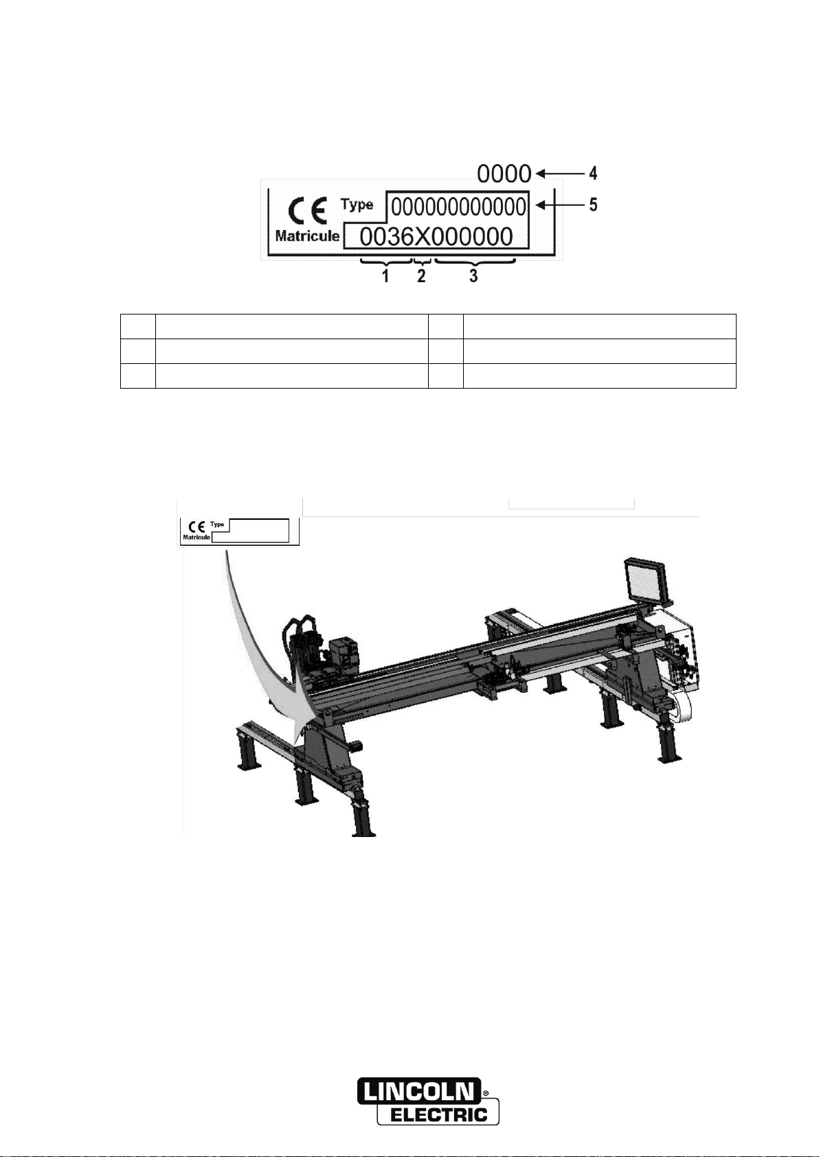
A - IDENTIFICATION.........................................................................................................................1
B - SAFETY INSTRUCTIONS............................................................................................................3
1 - GENERAL SAFETY INSTRUCTIONS................................................................................3
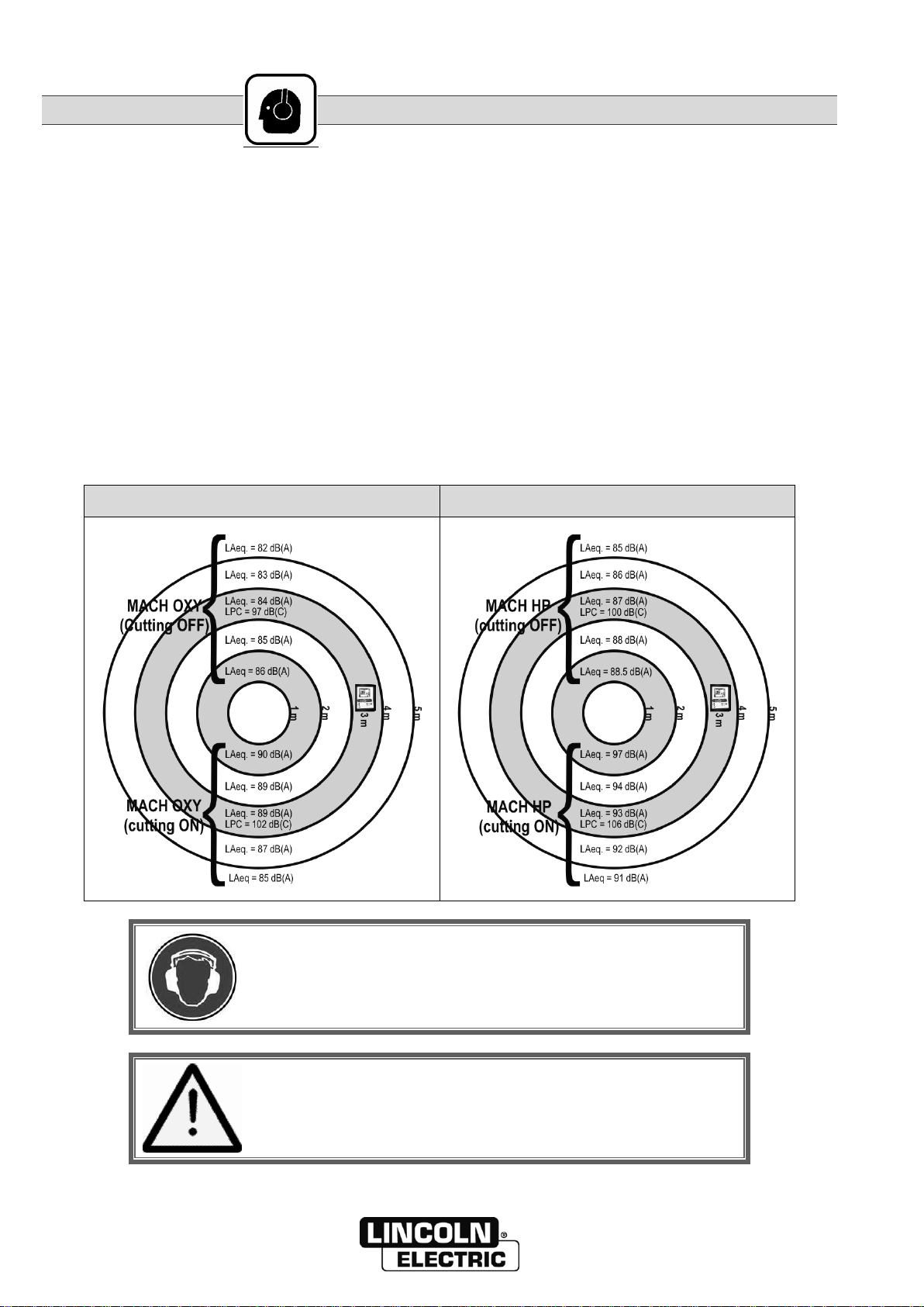
2 - AIRBORNE NOISE .............................................................................................................4
3 - ELECTRICAL SAFETY.......................................................................................................5
4 - USE OF PERSONAL PROTECTIVE EQUIPMENT............................................................5
5 - INSTRUCTIONS FOR THE USE OF GAS .........................................................................5
6 - CONDITIONS FOR USE.....................................................................................................6
7 - RISK OF HEATING.............................................................................................................7
C - DESCRIPTION .............................................................................................................................9
1 - POSSIBILITIES OF THE ESSENTIAL OXYCUTTING INSTALLATION............................9
2 - INSTALLATION ON LINCOLN ELECTRIC MACHINE.......................................................10
3 - ESSENTIAL OXY CUTTING GAS ASSEMBLY (REF. A)...................................................12
4 - CYCLE FUNCTION ASSEMBLY........................................................................................13
5 - ESSENTIAL OXYCUTTING SOLENOID VALVE ASSEMBLY (REF. B)............................13
6 - LONGITUDINAL BUNDLES (FL)........................................................................................14
7 - TRANSVERSE BUNDLES (FT)..........................................................................................14
8 - TOOL HOLDER (REFERENCE P) .....................................................................................14
9 - TORCH OPTION (REFERENCE OC).................................................................................15
10 - FUEL GAS REGULATION KIT .........................................................................................15
D - MONTAGE INSTALLATION........................................................................................................17
1 - CONDITIONS OF INSTALLATION.....................................................................................17
2 - CONNECTION....................................................................................................................19
E - OPERATOR MANUAL.................................................................................................................21
1 - OPERATOR CONTROLS...................................................................................................21
2 - ADJUSTMENTS..................................................................................................................22
3 - GAS SUPPLY CHANGE.....................................................................................................22
4 - CYCLE ................................................................................................................................23
F - MAINTENANCE............................................................................................................................25
1 - SERVICING.........................................................................................................................25
2 - TROUBLESHOOTING........................................................................................................27
3 - SPARE PARTS...................................................................................................................31
PERSONAL NOTES ..........................................................................................................................38

8695 4985
II ESSENTIAL OXYCUTTING
INFORMATIONS
DISPLAYS AND PRESSURE GAUGES
The measuring devices or displays for voltage, current, speed, pressure, etc., whether analog or digital, should be
considered as indicators
For operating instructions, adjustments, troubleshooting and spare parts see safety instructions for use and
maintenance
ISEE N° : 8695 7050 : Safety instructions
8695 4986 : Optional Essential torch ignition
8695 4987 : Optional Essential sensing
MACH HP torch option instruction manual
MACH OXY torch option instruction manual
8695 4673 : OXY VXK bevelling unit option
REVISIONS
REVISION B 10/16
DESIGNATION
PAGE
Creation in several languages
REVISION C 09/18
DESIGNATION
PAGE
To change logos
REVISION D 09/18
DESIGNATION
PAGE
Update
E-23

8695 4985 / C
ESSENTIAL OXYCUTTING A-1
A - IDENTIFICATION
Please enter the number of your equipment in the following box.
Quote this information in all correspondence.
1
Manufacturing factory code
4
Year manufactured
2
Manufacturing year code
5
Product type
3
Product serial no.

A - IDENTIFICATION 8695 4985 / C
A-2 ESSENTIAL OXYCUTTING

8695 4985 / C
ESSENTIAL OXYCUTTING B-3
B - SAFETY INSTRUCTIONS
1 - GENERAL SAFETY INSTRUCTIONS
Before using the process, make sure you read the manual,
particularly the general safety instructions and those specific to
this process.
The machine must be operated by a person trained in its use and
hazards.
For general safety instructions, please refer to the specific
manual supplied with the equipment, reference 8695 7050
Special security instructions are also recommended in the
documentation of the options or the extraction table.

B - SAFETY INSTRUCTIONS 8695 4985 / C
B-4 ESSENTIAL OXYCUTTING
2 - AIRBORNE NOISE
1 - Measurement Site Qualification
The machine was tested in the
LINCOLN ELECTRIC FRANCE
ZI rue Lavoisier, BP009
79200 PARTHENAY FRANCE.
central assembly building
This site has been qualified by APAVE (Nord Ouest)
5 rue de la Johardière
44800 Saint Herblain FRANCE
This qualification was the subject of Report n°12296847/2
2 - Measurements
MACH OXY
MACH HP
The use of a helmet is required with a noise level above 80dB, for
the operator and for persons located nearby.
The noise generated by the process can cover external sound
warnings.

8695 4985 / CB - SAFETY INSTRUCTIONS
ESSENTIAL OXYCUTTING B-5
3 - ELECTRICAL SAFETY
The flame cutting gas cabinet is supplied with 230V power. Risk
of electric shock or electrocution. It is locked with a removable
key.
After the work, lock the cabinet once again before switching on
the power.
Any work on the cabinet must be carried out by approved
personnel. The emergency stop does not shut down the power
supply of the manifold box.
The remainder of the flame cutting installation is powered with 24VDC, +/-12VDC, 24VAC. The igniter manages
high voltage at low intensity.
4 - USE OF PERSONAL PROTECTIVE EQUIPMENT
In the operating phase, and also in the adjustment phase, appropriate personal protection is required (see
document 8695 7050 for more details).
Standard EN 169 requires the use of shade 7 dark glass for the outputs from this process.
5 - INSTRUCTIONS FOR THE USE OF GAS
See section 3, Safe use of gas of the document 8695 7050, particularly the use of oxygen, propane and acetylene.
Oxygen is an oxidant; it activates combustion.
Acetylene is corrosive to copper: do not use brass with more than 70% copper content
Fuel gases are particularly flammable materials
The machine is not designed for operating in an explosive atmosphere.

B - SAFETY INSTRUCTIONS 8695 4985 / C
B-6 ESSENTIAL OXYCUTTING
By definition, fuels are highly flammable. The machine does not generate ATEX zones in normal use or in the event
of potential fuel leaks, if the conditions of installation, maintenance use and checking are followed. However, such
potential leaks can be involved in the overall calculation of ATEX zoning of a plant or workshop. Upon request, we
can supply the characteristics of our machine for such rating.
All our fittings and valves are placed in the open air. To avoid hazards, it is thus indispensable for the machine to be
installed in a large and well ventilated workshop, and the sheet to cut must necessarily be placed on a extraction
table that removes burnt gas and also unburnt fuel gas that may be present in the vicinity of the torches.
When the machine is not in use, the gas supplies must be shut
We have used the following hypotheses for the calculation of ATEX zoning:
- The machine may not be used in workshops with a volume less than 2000m3
- The maximum gas supply pressure data stated in these instructions must be followed
- The machine may not be used in workshops with air renewal less than 6/hour
- The checking of leaks from valves and fittings is required every month.
If these conditions are not met, please contact us.
For cutting/welding workshops, a minimum air renewal rate of 15/hour is recommended.
6 - CONDITIONS FOR USE
The installation is designed to operate with an appropriate extraction table (please call us for rating). Regularly
check the effectiveness of the extraction.
Under the standard EN ISO 15012-4 , the following speeds are required for oxycutting in respect of the table:
- 1m/s for thicknesses below 100mm
- 1.2m/s for thicknesses between 100 and 200mm
The installation is designed to operate with only one type of fuel gas. Please contact us for all gas type changes.
The installation is designed for cutting steel. Take particular precautions for the cutting of other materials (painted
steel, film-wrapped steel etc.) indicated by the manufacturer of the material.
No smoking and no disposing of debris or any combustible
material in the cutting table or on the sheet.
For example, if oil is used on the sheet, it must not be
combustible.
Adjust the method so that any impurities from the process are
not thrown more than two metres around the torch.
The installation is designed to operate under the monitoring of an operator.
The installation is designed for working at an ambient temperature from 0 to 35°C. The machine is designed for
operating inside a workshop. If the machine must operate outside these conditions, please contact us.
Switch off the energy to the machine before maintenance.

8695 4985 / CB - SAFETY INSTRUCTIONS
ESSENTIAL OXYCUTTING B-7
7 - RISK OF HEATING
When the machine cuts pieces:
- that are small (e.g. where one dimension is less than 100 mm),
- nested closely,
- with several torches set close to each other (e.g. 150 - 500 mm)
The sheet temperature may rise (above 300°C for instance). As a
result, the mechanical systems located near and above the
oxycutting nozzles may be exposed to high temperatures and be
damaged rapidly (components, pipes, wires).
Heating of parts also disrupts sensing, and thus adversely affects the cutting quality.
THE SOLUTION MAY CONSIST IN :
- modifying the cutting program to distance the succession of cuts while cutting the pieces,
- and/or using a cutting table with fume extraction so as to carry away as many calories as possible from the bottom
of the sheet (so as to avoid the rise of calories above the sheet).
If these measures do not deliver the expected result, the customer should ask for assistance from the
manufacturer.

B - SAFETY INSTRUCTIONS 8695 4985 / C
B-8 ESSENTIAL OXYCUTTING

8695 4985 / C
ESSENTIAL OXYCUTTING C-9
C - DESCRIPTION
1 - POSSIBILITIES OF THE ESSENTIAL OXYCUTTING INSTALLATION
This is a complete installation made up of a series of
industrial equipment (manifold box, solenoid-valve
assembly, torches), specially designed to allow
automatic thermal cutting with oxycutting.
Oxycutting is a process where metal is cut off by the
localised and continuous combustion of a jet of pure
oxygen.
NB: The speed and quality pair can be selected
differently depending on the end destination of
the cut parts.
Quality and productivity requirements: closer
metallurgical, dimensional or geometrical tolerances,
surface conditions, speed etc. make it necessary to
use modern guiding machines.
The cutting values and speeds depend on the type of torch and gas used.
Gas usable with all torches:
- Propane
- Acetylene
- Natural gas
Oxycut Machoxy torch:
Cutting capacity: 6 to 200mm
Mid sheet cutting possible up to 100mm
Mach HP torch:
Cutting capacity: 6 to 200mm
Mid sheet cutting possible up to 100mm

C - DESCRIPTION 8695 4985 / C
C-10 ESSENTIAL OXYCUTTING
2 - INSTALLATION ON LINCOLN ELECTRIC MACHINE
This installation may be used in an integrated manner on a machine supplied by us. The main functions are
accessible by the NC. This installation can manage the plasma cutting function for a maximum of 2 torches, and
the oxycutting function for a maximum of 4 torches depending on the modules selected.
.

8695 4985 / CC - DESCRIPTION
ESSENTIAL OXYCUTTING C-11
ESSENTIAL OXYCUTTING INSTALLATION
ITEM
DESIGNATION
SPECIFIC
INSTRUCTIONS
A
Essential oxy cutting gas assembly
-
B
Essential oxycutting solenoid valve assembly
-
C
Cycle function assembly
-
OP
Sensing option
8695 4987
OA
Ignition option
8695 4986
OC
Torch option
Supplied with the
torch
FL
Longitudinal bundles
-
FT
Transverse bundles
-
G1
Fuel
-
G2
Oxygen (Heating and Cutting)
-
I
Programming interface
8695 4944
P
Tool holder
Supplied with the
tool holder

C - DESCRIPTION 8695 4985 / C
C-12 ESSENTIAL OXYCUTTING
3 - ESSENTIAL OXY CUTTING GAS ASSEMBLY (REF. A)
This box can power 1 to 4 torches.
You can use one gas assembly for cutting up to thickness:
-200 mm with 1 torch
-80 mm for 2 torches
-60 mm for 3 torches
-50mm for 4 torches
Beyond that, another gas assembly must be installed.
A machine may have only one gas assembly, and thus 4 torches.
The functions of the assembly are as follows:
-Regulating the gas pressure going to the torches
-Flushing the cutting and heating oxygen line at the end of cutting/the program.
There is a specific box model for the use of acetylene.
For other fuel gases, the propane model is used.
The box is supplied wired in the machine, as in the electrical diagram. If the electrical cable is replaced, please
contact us.

8695 4985 / CC - DESCRIPTION
ESSENTIAL OXYCUTTING C-13
4 - CYCLE FUNCTION ASSEMBLY
These cycle functions are integrated into the main cabinet of the machine. They are intended for:
-Controlling the disconnecting and analogue valves on the gas assembly.
-Controlling the valves that are on the solenoid valve assembly on each torch
-Controlling ignition, if the option is installed
-Controlling the sensing function and processing feedback from sensing, if the option is installed
-Controlling the tool holder position (vertical movement)
5 - ESSENTIAL OXYCUTTING SOLENOID VALVE ASSEMBLY (REF. B)
This assembly is present for each installed torch. It is assembled on the tool holder carriage.
The commands come from the oxy cutting gas assembly to which it is connected.
It includes the controls of solenoid valves dedicated to each torch, and the igniter controls.
There is a specific solenoid valve assembly model for the use of acetylene.
For other fuel gases, the propane model is used.

C - DESCRIPTION 8695 4985 / C
C-14 ESSENTIAL OXYCUTTING
6 - LONGITUDINAL BUNDLES (FL)
Longitudinal bundles relating to oxycutting are standardised:
-Heating and cutting oxygen pipe, blue
-Fuel pipe: red/orange for acetylene, propane, natural gas, orange for other fuel gases (flamal)
-Air pipe: optional if the sensing option is present
7 - TRANSVERSE BUNDLES (FT)
Transverse bundles relating to oxycutting are standardised:
-Blue heating and cutting oxygen pipe: from gas assembly to solenoid valve assembly
-Fuel pipe: red/orange for acetylene, propane, natural gas; orange for the other fuel gases, from the gas
assembly to the solenoid valve assembly
-Solenoid valve control bundle: from the gas assembly to the solenoid valve assembly
-Tool holder control bundle: from the gas assembly to the tool holder
-Tool holder power bundle: from main cabinet to tool holder
-Air pipe: optional if the sensing option is present
8 - TOOL HOLDER (REFERENCE P)
The tool holder is used for raising and lowering the torch. There is one tool holder per torch.
It is powered from the main cabinet.
It has a torch holder ring that can be turned for bevel cutting or for vertical adjustment.
The motor commands come from the oxy cutting gas assembly to which it is connected.
Refer to the special documentation of the tool holder for more details.

8695 4985 / CC - DESCRIPTION
ESSENTIAL OXYCUTTING C-15
9 - TORCH OPTION (REFERENCE OC)
The function of the torch is to diffuse and adjust the gas flows so as to achieve high quality cutting. The torch is
fixed to the tool holder.
The Essential flame cutting installation is designed for working with Mach Oxy and Mach HP torches.
Refer to the torch documentation for more details about the torches and associated options (consumables, angle
adapters, strip cutting etc.)
10 - FUEL GAS REGULATION KIT
If the customer’s fuel gas network is unstable, we recommend the use of a gas regulation kit that includes a
pressure reducer valve.
The kit is fitted on the fuel gas line before the Essential oxy cutting solenoid valve assembly.
There is a specific kit for propane, and another one for acetylene.

C - DESCRIPTION 8695 4985 / C
C-16 ESSENTIAL OXYCUTTING
Table of contents
Other Lincoln Electric Cutter manuals

Lincoln Electric
Lincoln Electric MASTERPIPE Mini Profiler Operating instructions

Lincoln Electric
Lincoln Electric OPTITOME2 HPC III User manual

Lincoln Electric
Lincoln Electric Torchmate 5100 Series User manual

Lincoln Electric
Lincoln Electric Torchmate 5100 Series Operating instructions

Lincoln Electric
Lincoln Electric Torchmate 4400 User manual

Lincoln Electric
Lincoln Electric PRO-CUT 60 User manual

Lincoln Electric
Lincoln Electric LINC-CUT S 1020w User manual

Lincoln Electric
Lincoln Electric Growth Series User manual

Lincoln Electric
Lincoln Electric OPTITOME II Series Mounting instructions

Lincoln Electric
Lincoln Electric Torchmate 5100 Series User manual