manuals.online logo
Brands
  1. Home
  2. •
  3. Brands
  4. •
  5. TRQ
  6. •
  7. Lighting Equipment
  8. •
  9. TRQ PH V2 AT ECO LED Seres User manual

TRQ PH V2 AT ECO LED Seres User manual

SELF CONTAINED EMERGENCY LIGHT
SERIE SIRAH PH V2 AT ECO LED
Characteristics:
- Supply 230V~ 50/60Hz.
- Power: <5W.
- Maintained or non maintained (selectable by JUMPER). Maintained: with JUMPER. Non maintained: without JUMPER.
- Test button and Telemando (optional by order).
- Self test. Automatic and manual verification test.
- Green LED indicates main presence and correct operation of the equipment (Left LED).
- Red LED indicates failure (Right LED).
- Intelligent control of battery charge: 2 load levels (full charge and maintenance charge).
- Battery Ni Cd.
- Protection end of Battery Discharge.
- Battery charging: 24 hours.
- PCB LED 2835 white, high luminosity, working life > 50000 hours.
- Colour temperature 6000K 7000K.
- White Opal diffuser.
- Grade IP42 / IP65 depending on the model.
- Connection via 6 or 8 mm cable (IP42 model).
- Connection via PVC pipe 16 or 20mm (IP65 model).
- Class II luminary.
- Dimensions: 261x124x56mm (models IP42) and 271x146x75mm (models IP65).
- CE marked as per directives 2014/35/UE and 2014/30/UE of EMC.
- Manufactured according to norms UNE EN 60598 2 22.
IP42 models IP65 models Emergency lamp Battery Ni Cd
Autonomy  Luminous flux
Lumen
P
H
75
V2
AT
ECO LED
E
P
H
75
V2
AT
ECO LED
PCB
24
LED 28
35
1.2V 0.9
1Ah
1 hour
75
P
H
100
V2
AT
ECO LED
E
P
H
100
V2
AT
ECO LED
PCB
24
LED 28
35
1.2V 0.9
1Ah
1 hour
100
P
H
150
V2
AT
ECO LED
E
P
H
150
V2
AT
ECO LED
PCB
24
LED 28
35
3.6
V 0.8
1A
h
1 hour
150
P
H
200
V2
AT
ECO
LED
E
P
H
200
V2
AT
ECO LED
PCB
24
LED 28
35
3.6
V 0.8
1A
h
1 hour
230
P
H
300
V2
AT
ECO LED
E
P
H
300
V2
AT
ECO LED
PCB
24
LED 28
35
3.
6
V
1
.
2
Ah
1 hour
320
PH
400 V2 AT ECO LED
E
P
H
4
00
V2
AT
ECO LED
PCB
24
LED 28
35
3.
6
V
1
.
2
Ah
1 hour
400
P
H
102
V2
AT
ECO LED
E
P
H
102
V2
AT
ECO LED
PCB
24
LED 28
35
3.
6
V
1
.
2
Ah
2 hours
100
P
H
152
V2
AT
ECO LED
E
P
H
152
V2
AT
ECO LE
D
PCB
24
LED 28
35
3.
6
V
1
.
2
Ah
2 hours
150
P
H
202
V2
AT
ECO LED
E
P
H
202
V2
AT
ECO LED
PCB
24
LED 28
35
3.
6
V
1
.
2
Ah
2 hours
230
P
H
302
V2
AT
ECO LED
E
P
H
30
2
V2
A
T
ECO LED
PCB
24
LED 28
35
3.
6
V
1
.
6
Ah
2 hours
300
P
H
103
V2
AT
ECO LED
E
P
H
103
V2
AT
ECO LED
PCB
2
4
LED 28
35
3.
6
V
1
.
2
Ah
3
hours
100
P
H
153
V2
AT
ECO LED
E
P
H
153
V2
AT
ECO LED
PCB
24
LED 28
35
3.
6
V
1
.
2
Ah
3 hours
150
PH
203
V2
AT ECO LED
EPH
203
V2
AT ECO LED
PCB
24
LED 28
35
3.
6
V
1
.
6
Ah
3
hours
230
Installati n:
- Switch off the main power.
- Remove the cover and install the luminary and select the M/NM mode with the JUMPER.
- Make electrical connections and switch on the power. The Green LED will go ON and LED lamp will go ON (Maintained mode).
- The luminary will not respond to its autonomy till 1st 24 hours as the batteries are supplied discharged.
Self-test:
The equipment makes an automatic test of operation verifying the LED LAMP and the BATTERY.
- Monthly test (once a month for 30 sec.). Green LED blinking slowly.
- Annual test (once a year for 1 hour). Green LED blinking fast.
Test results:
1. GREEN LED ILLUMINATED: Power ON and status OK.
2. RED LED BLINKING FAST: LED lamp failure (Short circuit LED or open circuit LED).
3. RED LED BLINKING SLOWLY: Battery failure (open battery or disconnected).
4. RED LED ILLUMINATED: Battery failure (defective or low battery, does not comply with autonomy).
RESET: Disconnect the battery some seconds to do a RESET and remove the fault alarm.
Manual test verificati n:
The equipment makes a manual test of operation when press the button Test or Telemando (press ON).
1. Pressing from 1 to 3 sec., simulates emergency operation (mains failure).
2. Pressing from 4 to 5 sec., run the monthly verification test.
3. Pressing from 6 to 7 sec., run the annual verification test.
4. In a main failure situation (emergency function) pressing more than 7 sec., LEDs go OFF.
Maintenance:
Before doing any maintenance operation, please make sure that the main supply is switched off and the luminary is in STAND BY position.
The batteries should be changed once their duration gets inferior to the assigned.
The luminaries should be checked at least once a year.
The batteries and LED PCB should be re cycled or eliminated in an adequate way.
C nnecti n diagram:
IP42 IP65
Lighting Technologies TRQ, S. L.
IP42 m dels
JUMPER
Maintained: Jumper ON
Non maintained: Jumper OFF
IP65 m dels
 Break the round area of the base and place the rubber hose for the entrance of the PVP pipe.
 Mount the emergency on the wall using the 2 screws supplied with rubber washer to maintain the IP65 grade.
 Connect the power supply cables (230V) to the terminal strip.
 Reassemble the opal diffuser with 4 screws.

Remove the cover by using a screwdriver
lifting the cover upwards.

Install, cut the rubber & pass the cable to make connections.
FULLY RECESS IN FALSE
CEILING
Plaster: X=277mm Y=133mm
Plasterboard: Use the frame (ST-
28) with the clips ST 21
SEMI RECESS IN FALSE CEILING
Plaster: X=251mm Y=115mm
Plasterboard: use clips ST 21

Unscrew 4 screws and remove the opal diffuser

Remove the reflector using a screwdriver

This manual suits for next models

26

Other TRQ Lighting Equipment manuals

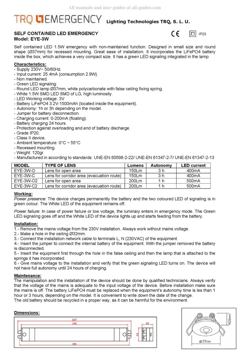
TRQ EYE-3W User manual

TRQ

TRQ EYE-3W User manual

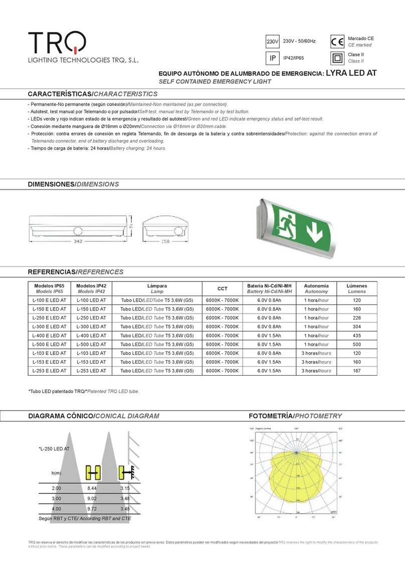
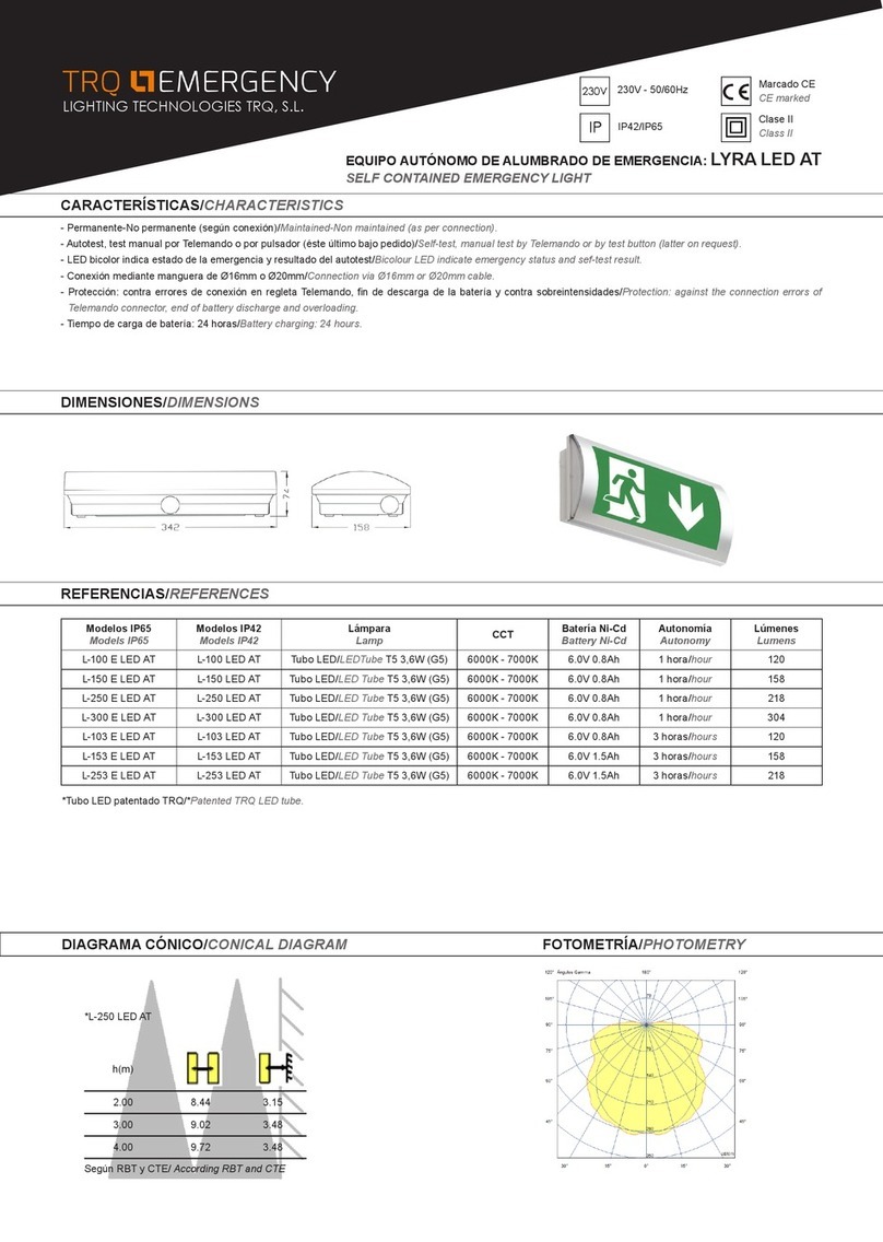
TRQ LYRA L-100 E LED AT User manual

TRQ

TRQ LYRA L-100 E LED AT User manual

TRQ K-501 User manual

TRQ

TRQ K-501 User manual

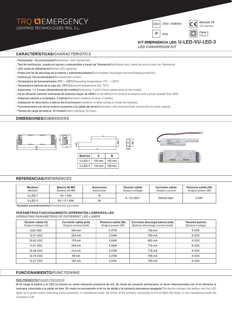
TRQ U-LED-1 User manual

TRQ

TRQ U-LED-1 User manual

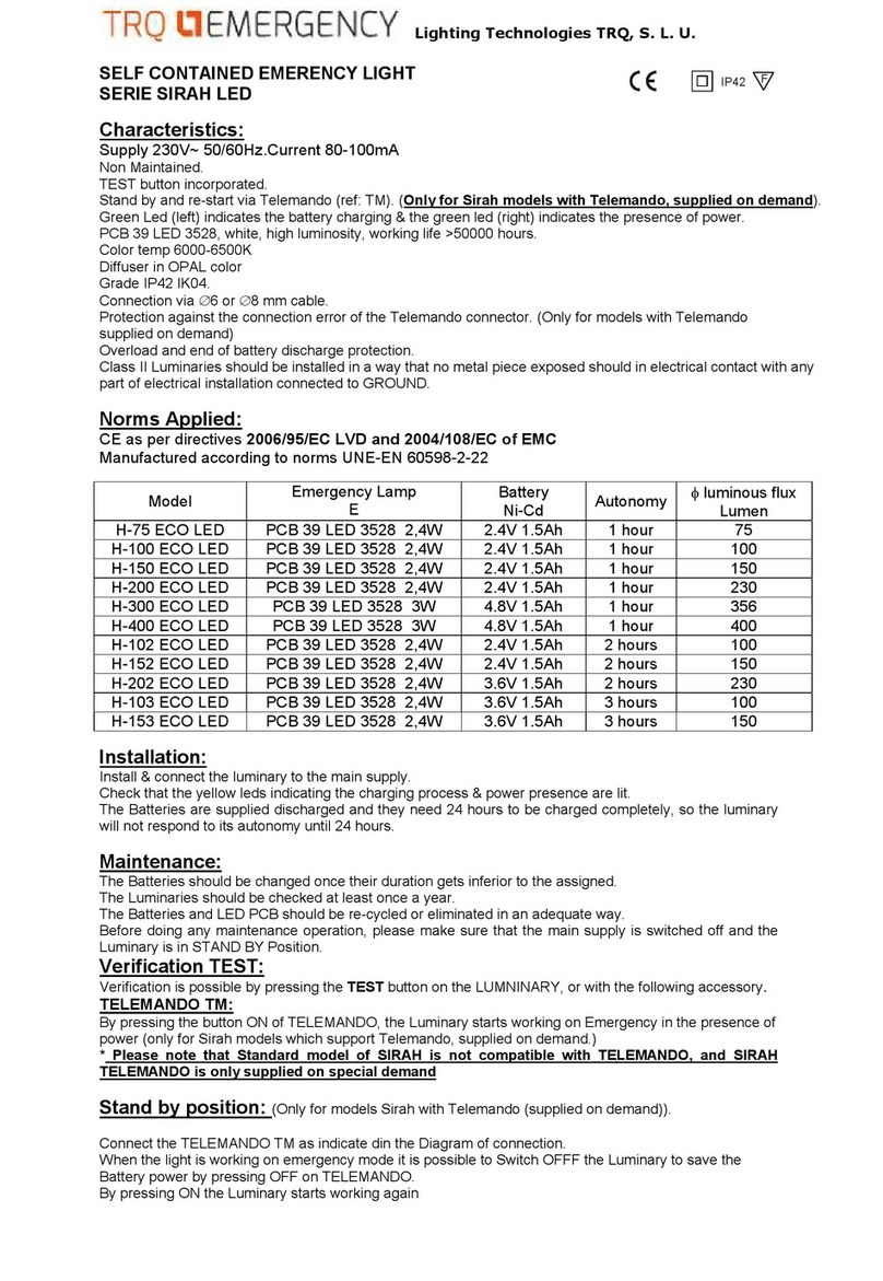
TRQ SIRAH LED Series User manual

TRQ

TRQ SIRAH LED Series User manual

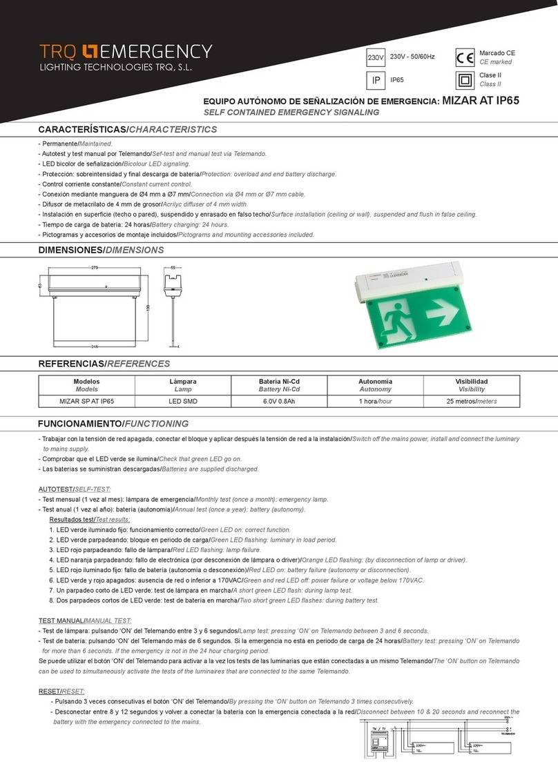
TRQ MIZAR SP AT IP65 User manual

TRQ

TRQ MIZAR SP AT IP65 User manual

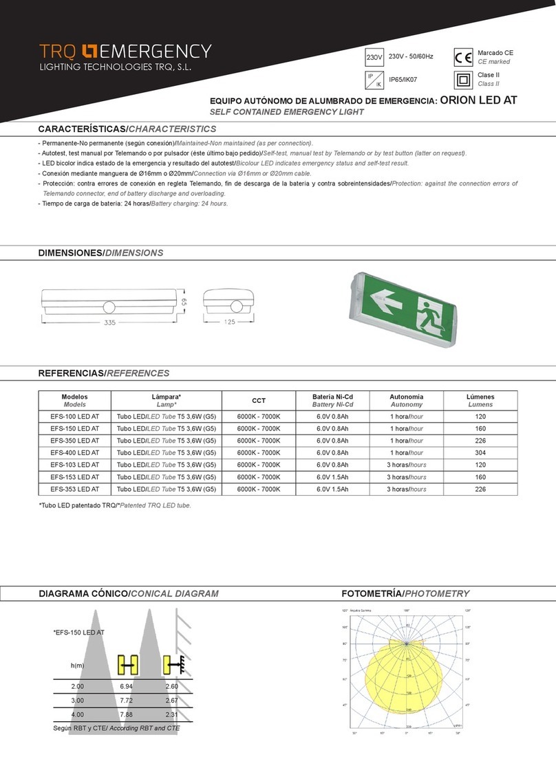
TRQ EMERGENCY ORION EFS-100 LED AT User manual

TRQ

TRQ EMERGENCY ORION EFS-100 LED AT User manual

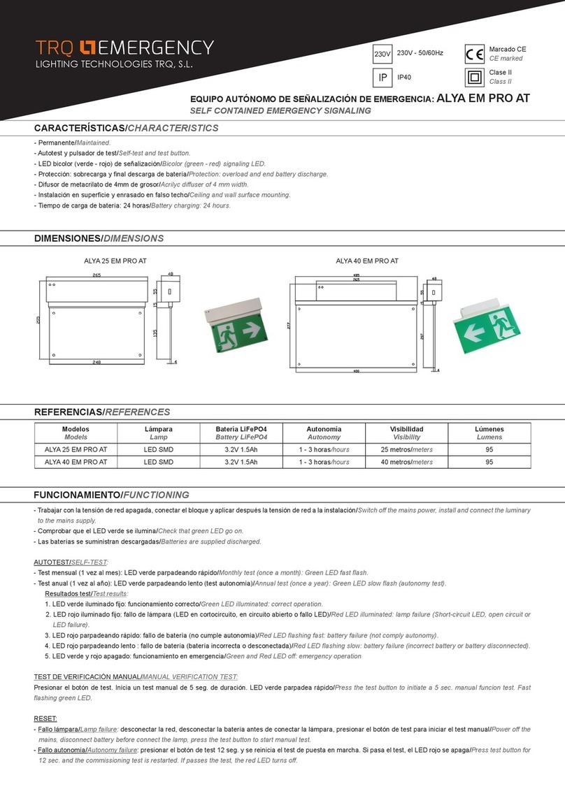
TRQ ALYA 25 EM PRO AT User manual

TRQ

TRQ ALYA 25 EM PRO AT User manual

TRQ SOL Series User manual

TRQ

TRQ SOL Series User manual

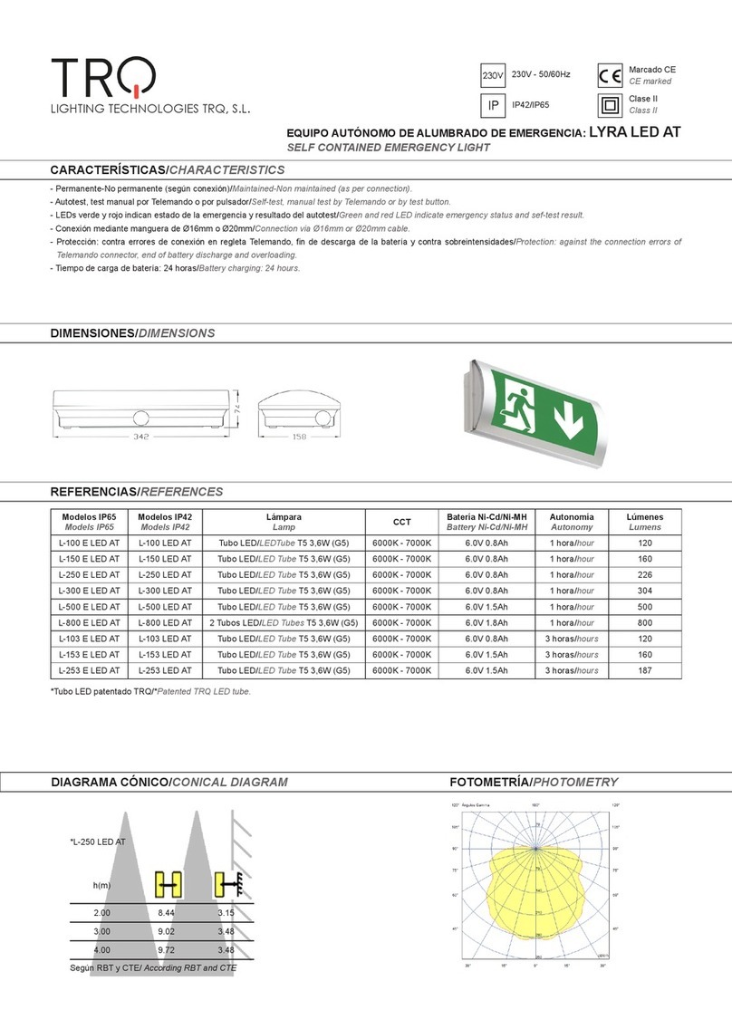
TRQ L-100 E LED AT User manual

TRQ

TRQ L-100 E LED AT User manual

TRQ L-500 E LED AT User manual

TRQ

TRQ L-500 E LED AT User manual

Popular Lighting Equipment manuals by other brands

Ledj TRI LED-56 CAN user manual

Ledj

Ledj TRI LED-56 CAN user manual

LANSING LIGHTING JCL50F manual

LANSING LIGHTING

LANSING LIGHTING JCL50F manual

Dolan-Jenner Fiber-Lite PL800 Series Operation manual

Dolan-Jenner

Dolan-Jenner Fiber-Lite PL800 Series Operation manual

Flight Light HL490 installation manual

Flight Light

Flight Light HL490 installation manual

Anslut 019937 operating instructions

Anslut

Anslut 019937 operating instructions

Utilitech DLS30-06F27D1E-WH-F1 Package Contents

Utilitech

Utilitech DLS30-06F27D1E-WH-F1 Package Contents

Beamz professional WH180RGB instruction manual

Beamz professional

Beamz professional WH180RGB instruction manual

Portland Ecolux Solar Installation/Wiring Instructions

Portland

Portland Ecolux Solar Installation/Wiring Instructions

Dialight VIGILANT Series manual

Dialight

Dialight VIGILANT Series manual

SCHOTT VisiLEDs MC Series operating instructions

SCHOTT

SCHOTT VisiLEDs MC Series operating instructions

Sulion 112320 manual

Sulion

Sulion 112320 manual

Beamz BSS50 instruction manual

Beamz

Beamz BSS50 instruction manual

Well Red Coronet Safety, Assembly and Use

Well Red

Well Red Coronet Safety, Assembly and Use

Flair 10358747 Mounting instructions

Flair

Flair 10358747 Mounting instructions

Dialight HBXREF22 manual

Dialight

Dialight HBXREF22 manual

Feniex Fusion L-6016 instruction manual

Feniex

Feniex Fusion L-6016 instruction manual

wofi 333801 9100 Series quick start guide

wofi

wofi 333801 9100 Series quick start guide

EuroLite LED PAR-64 RGBW 48x3W IP65 user manual

EuroLite

EuroLite LED PAR-64 RGBW 48x3W IP65 user manual

manuals.online logo
manuals.online logoBrands
  • About & Mission
  • Contact us
  • Privacy Policy
  • Terms and Conditions

Copyright 2025 Manuals.Online. All Rights Reserved.