TRU-BOLT 1742006 User manual

M1742002 1742006 V1
Bluetooth Square Electronic Deadbolt

INDEX
I. INSTALLATION INSTRUCTIONS
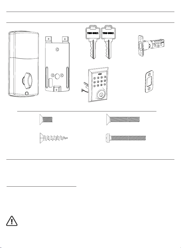
Package Contents / Tools Required.....................................................Page 1
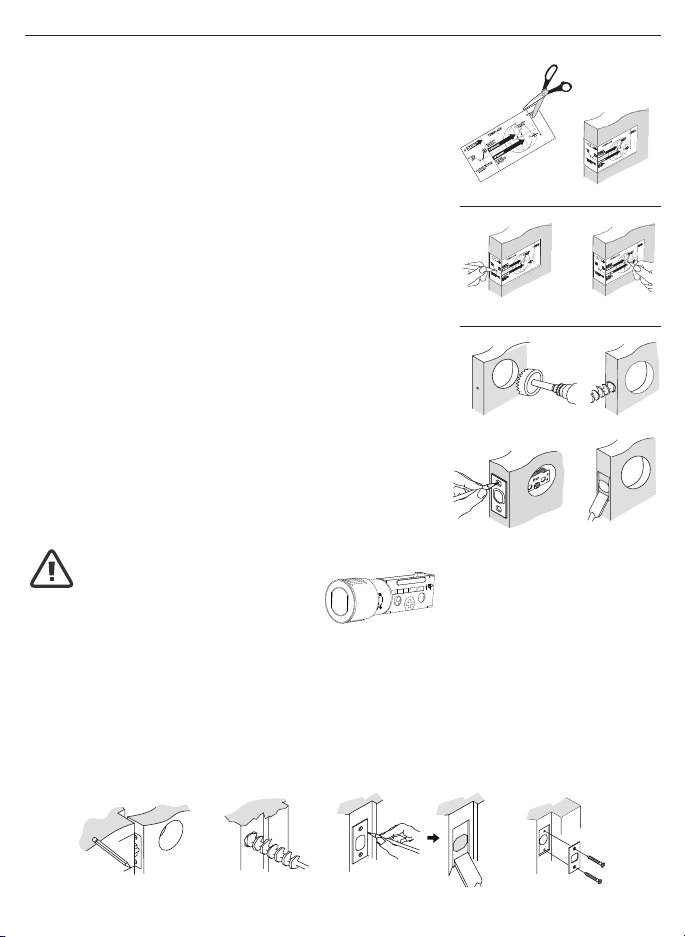
Prepare Door and Jamb.........................................................................Page 2
Adjusting Deadbolt Latch Set...............................................................Page 3
Installing Deadbolt Latch Set............................................................... Page 4
Preparing Interior Assembly.................................................................Page 5
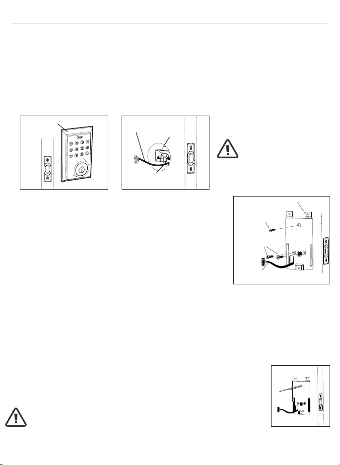
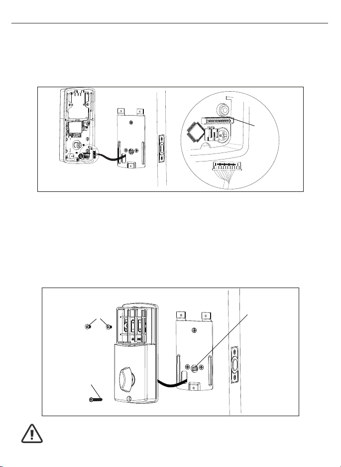
Installing Exterior Assembly..................................................................Page 6
Installing Interior Assembly...................................................................Page 7-8
II. MOBILE APPLICATION INSTRUCTIONS
My Key Mobile™ Application Installation & Use / App Setup............Page 9
Add & Remove Locks / Using the App.................................................Page 10-11
Lock Settings..........................................................................................Page 11
eKey / Passcodes / Users / Records...................................................Page 12-15
Main Menu..............................................................................................Page 16
III. PHYSICAL KEYPAD OPERATION AND INSTRUCTIONS
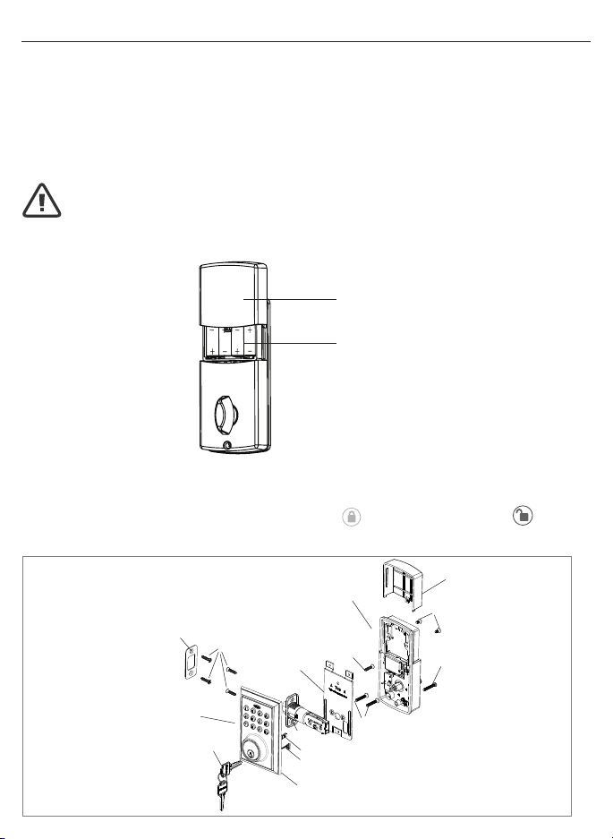
Exterior Assembly Overview.................................................................Page 17
Turn On/Off Auto Lock Function / Sound Off / Sound On /
Restore Factory Settings.....................................................................Page 18
Add Administrator / Customize Passcodes Received from the App /
Enable/Disable Auto-Lock / Vacation Mode /
Disable Vacation Mode.........................................................................Page 19
IV. ASSISTANCE
Consumer Friendly Message Guide / Programming Records..........Page 20
Installation Trouble Shooting ..............................................................Page 21
Template ................................................................................................Page 23-24
Consumer Assistance...........................................................................Page 25
FCC Regulatory Compliance................................................................Page 26
Limited Warranty....................................................................................Page 27

Page 1
I. INSTALLATION INSTRUCTIONS
PACKAGE CONTENTS
TOOLS REQUIRED
Tools Required for Installation on Pre-drilled Doors:
• Phillips Screwdriver
NOTE: DO NOT USE a drill.
Tools Required for Installation
on Doors That Require Drilling:
• Drill
• Tape Measure
• Pencil
• 2-1/8” (54mm) Drill Hole Saw
• 1” (25mm) Drill
• 1/16” (2mm) Drill
• Chisel
• Hammer
• Phillips Screwdriver
DO NOT RETURN TO STORE! If any parts are missing or damaged,
please call Customer Service toll free at 1-800-860-1677 (Toll Free, M-F 7am – 5pm PST)
Online installation videos can be viewed at TruBoltLocks.info
Exterior Assembly
Entry keys (2 ea.)
Mounting Plate
Interior Assembly
Deadbolt Strike Plate
Deadbolt Latch Set (Adjustable)
2-3/8” (60mm) to 2-3/4” (70mm)
Electronic lock requires (4) High Quality
AA Alkaline batteries. When all 4 batteries
are installed in the correct position, hear 2
beeps and the keypad will illuminate blue.
DO NOT TOUCH the keypad until the keypad
stops illuminating.
BATTERIES (NOT INCLUDED)
PAY CLOSE ATTENTION TO ALERTS
3/4” (19mm) Screws - 5 ea. 1” (25mm) Screw - 1 ea.
5/16” (8mm) Screws - 2 ea. 7/8” (22mm) Screws - 2 ea.
A
C
B
D

Page 2
NOTE: For installation on doors with pre-drilled holes skip to page 4.
1. TEMPLATE
a. Cut out template printed on page 15 & 16 of this Manual
(Figure 1a).
b. Fold template and place on door 36” (915mm) from
the ground as marked (Figure 1b).
2. MARK THE DOOR FOR DRILLING
b. Mark center hole on door edge through guide on
template for 1” (25mm) latch bolt (Figure 2a).
a. Mark center hole on door face through guide on
template for 2-3/8” (60mm) or 2-3/4” (70mm)
backset (Figure 2b).
3. DRILL AND CHISEL DOOR
a. Drill 2-1/8” (54mm) hole through door face as marked
for lock set (Figure 3a).
b. Drill 1” (25mm) hole in center of door edge for
Deadbolt Latch Assembly (Figure 3b).
c. Insert Deadbolt Latch Assembly in hole keeping it
parallel to face of door. Mark outline and remove latch
(Figure 3c).
d. Chisel 1/8” (3mm) deep or until latch face is ush
with door edge (Figure 3d).
4. MARK AND DRILL DOOR JAMB
a. Mark center hole on edge of jamb even with the center of the Latch Bolt on door
edge. (Figure 4a).
b. Drill 1” (25mm) hole 1-3/16” (30mm) deep in door jamb on center mark
(Figure 4b).
c. Outline outside edges of Strike Plate (Figure 4c).
d. Chisel 1/8” (3mm) deep for Strike Plate or until ush (Figure 4d).
e. Install Strike Plate using two 3/4” (19mm) screws provided (Figure 4e).
PREPARE DOOR AND JAMB
Figure 4a Figure 4b Figure 4c Figure 4e
Figure 4d
NOTE: For Drive in Latch, drill hole size indicated on template and press
until it is ush with door edge.
UP
Figure 1a
Figure 2a Figure 2b
Figure 3a
Figure 3c
Figure 1b
Figure 3b
Figure 3d

Page 3
ADJUSTING DEADBOLT LATCH SET
NOTE: Deadbolt Latch Set is shipped with the backset set at 2-3/8” (60mm)
Measure the backset (backset is distance between edge of the door and the
center of Lock).
1. TO CONVERT FROM 2-3/8” (60mm) BACKSET TO 2-3/4” (70mm) BACKSET
a. Hold latch with numbers facing forward and thumb pressing on the bolt (Figure 1a).
b. Rotate the cylinder cover clockwise (Figure 1b).
c. Pull and twist the extension plate all the way out (Figure 1c).
d. Rotate the cylinder cover counter clockwise so that the marking aligns with
the 2-3/4” (70mm) position indicator (Figure 1d).
2. TO CONVERT FROM 2-3/4” (70mm) BACKSET TO 2-3/8” (60mm) BACKSET
a. Hold latch with numbers facing forward and thumb pressing on the bolt (Figure 2a).
b. Rotate the cylinder cover clockwise (Figure 2b).
c. Push and twist the extension plate all the way in (Figure 2c).
d. Rotate the cylinder cover counter clockwise so that the marking aligns with
the 2-3/8” (60mm) position indicator (Figure 2d).
Figure 1a Figure 1b
Figure 1c
Your latch is now set 2-3/4” (70mm) backset
Cylindrical Cover Extension Plate
2-3/8”
(60mm) 2-3/8”
(60mm)
2-3/4”
(70mm)
Figure 1d
Figure 2a Figure 2b Your latch is now set 2-3/8” (60mm) backset
Cylindrical Cover Extension Plate
2-3/8”
(60mm) 2-3/8”
(60mm)
Figure 2c
Figure 2d
NOTE: Do not extend Cylindrical Cover past 2-3/4” (70mm)

Page 4
3. INSTALLING THE DEADBOLT LATCH SET (need phillips head screwdriver)
a. Insert Deadbolt Latch Set into door edge hole with the word
“UP” and the arrow on the extension plate facing UP. Cross
shaped spindle connector will be at the bottom of the Deadbolt
Latch Set (Figure 3a).
b. Make sure the face plate sits ush with the door. Do not force
the latch into the mortise ush. Chisel out excess material if
necessary for a ush t.
c. Using two 3/4” (19mm). screws provided, screw the latch into the
door with a hand held screwdriver. DO NOT OVER TIGHTEN.
4. IDENTIFYING YOUR DOOR HANDING
Stand outside the door.
a. If the hinges are on the left your door is Left Handed (Figure 4a and 4b).
b. If the hinges are on the right your door is Right Handed (Figure 4a and 4b).
INSTALLING DEADBOLT LATCH SET
Figure 3a
Deadbolt Latch Extended Deadbolt Latch Retracted
NOTE: Deadbolt Latch must be retracted when installing
NOTE: You are standing outside the door
OUT SWING DOOR IN SWING DOOR
Figure 4a
Left Handed Door
Hinges are on the left side
Left Handed Door
Hinges are on the left side
Right Handed Door
Hinges are on the right side
Right Handed Door
Hinges are on the right side
Figure 4b

Page 5
6. SET THE ENTRY SWITCH FOR LEFT OR RIGHT HANDED DOOR
a. Gently move the switch to “L” for Left Handed Door (Figure 6a).
b. Gently move the Switch to “R” for Right Handed Door (Figure 6b).
7. SET THE INTERIOR KNOB POSITION FOR LEFT OR RIGHT HAND HINGED DOORS
a. The Interior Knob goes in the Horizontal position for Left Handed Doors (Figure 7a).
b. The Interior Knob goes in the Vertical position for Right Handed Doors (Figure 7b).
PREPARING THE INTERIOR ASSEMBLY
NOTE: Make sure deadbolt Latch is retracted
5. UNPACK THE INTERIOR ASSEMBLY
a. Remove the battery cover by sliding the cover upward.
b. Locate the screws holding the Mounting Plate to the Interior Assembly. Remove the
screws to release the Mounting Plate from the Interior Assembly.
Entry Switch
(Left or Right)
Figure 6a-b
Right Handed Door
(Vertical)
Left Handed Door
(Horizontal)
Figure 7a Figure 7b

Page 6
9. SECURING THE EXTERIOR ASSEMBLY TO THE DOOR
a. From the side marked “This side against
door”, route the Control Wire through the
rectangular slot in the Mounting Plate (Figure 9a).
b. Place Mounting Plate against door with tailpiece passing
through the center hole in the three hole set (Figure 9b).
c. Secure the Mounting Plate to the Exterior Assembly using
two 7/8” (22mm) Screws(B) (Figure 9c).
d. Hand tighten with a Phillips Screwdriver leaving loosely
connected (Figure 9d).
e. Check that the Rubber Gasket is properly aligned and correct as necessary
(Figure 8a).
f. Check vertical alignment of the lock (Figure 9f).
g. Tighten securely with a hand held Phillips Screwdriver. DO NOT OVER TIGHTEN
10. OPTIONAL INSTALLATION
a. Using a 1/16” (2mm) drill bit, drill a pilot hole in your door using the
Mounting Plate upper hole as a guide (Figure 10a).
b. Insert one 3/4” (19mm) screw(C) and tighten.
8. INSTALLING THE EXTERIOR ASSEMBLY
Work with the Door Open for easy access.
a. Unpack the Exterior Assembly. Use care to not scratch the green circuit board
during handling and installation.
b. Check that the Rubber Gasket is properly seated on the Exterior Assembly (Figure 8a).
c. Insert the Exterior Assembly onto the door with the tailpiece going through the
Deadbolt Latch Set cross shaped spindle connector in the VERTICAL POSITION.
Route the Control Wire through the door under the Deadbolt Latch Set (Figure 8c).
NOTE: Tailpiece must
be positioned vertically
INSTALLING EXTERIOR ASSEMBLY
Control
Wire
Tailpiece (Vertical)
Latch
Hole
Figure 8c
Figure 10a
NOTE: Lock and unlock using the key to see if
the Deadbolt Latch is opening and closing easily.
Figure 8a
Rubber Gasket
Right handed door view
Mounting Plate
C - 3/4” (19mm) screw
(Optional)
B - 7/8” (22mm)
screws
Control Wire
Figure 9a-f

Page 7
INSTALLING INTERIOR ASSEMBLY
11. ATTACH THE CONTROL WIRE TO THE INTERIOR ASSEMBLY
a. Use care to attach the Control Wire male plug to the Interior Assembly female
socket connector.
b. Carefully insert the male plug, smooth side up, into the female socket on the
interior assembly. DO NOT FORCE! (Figure 11a).
12. ATTACH THE INTERIOR ASSEMBLY TO DOOR
a. IMPORTANT: Make sure the knob is in the vertical position for right hand door and
horizontal position for left hand door.
b. Make sure the tailpiece (Figure 12a) is in the vertical position.
c. Position the Interior Assembly over the vertically positioned tailpiece and carefully
push the Interior Assembly against the door (Figure 12a).
d. Using two 5/16” (8mm) screws and one 1” (25mm) screw, attach
the Interior Assembly to the Mounting Plate. DO NOT OVER TIGHTEN SCREWS
NOTE: Lock and unlock using Interior Knob to see if the
latch is opening and closing easily.
Match
Color
Figure 11a
Vertical Tailpiece
Figure 12a
A - 5/16”(8mm) screws
D - 1”(25mm) screw

Page 8
13. Installing Batteries
a. Slide battery cover up and remove.
b. Insert 4 AA high quality Alkaline batteries into the Battery Compartment in the
direction noted +/- on the Compartment. The Lock will beep 2 times, the keypad
will illuminate blue, and the Tru-Bolt button will ash green twice to signify that
it has received power (Figure 13a).
c. Replace battery cover and slide down on to the Interior Assembly to cover the
batteries (Figure 13b).
14. Testing Lock
a. Always test with the Door Open
b. Test the Lock using the Interior Knob. The bolt should move smoothly in and out.
c. Test the Lock using the Keypad. To lock press and then press “1234”
to unlock.
INSTALLING INTERIOR ASSEMBLY (CONT.)
Battery
Cover
4 AA
Batteries
NOTE: Do not touch the Keypad until the blue light turns off.
Do not use rechargeable batteries or non-alkaline batteries.
Figure 13a-b
INSTALLATION OVERVIEW
Strike Plate
Mounting Plate
C - Optional
3/4”(19mm)
Interior Assembly
Battery Cover
A - 5/16”(8mm) screws
D - 1”(25mm) screw
B - 7/8”(22mm) screws
Latch
Vertical Tailpiece
Exterior Assembly
Rubber Gasket
Control Wire
Keys
C - 3/4”(19mm)
screws

Page 9
II. MY KEY MOBILE™ APPLICATION INSTALLATION & USE
PRIMARY APP ICONS
Messages User
Unlock Users
Save RecordsMenu Dropdown
Edit
Settings eKey Passcode
KEYPAD SYMBOLS
USER TYPES
Administrative User - Able to send & delete eKeys &
Passcodes, change AP , and remove connected lock(s)
Authorized User - Able to send eKeys & Passcodes, can
delete only the eKeys & Passcodes they send
User - Able to use eKeys & Passcodes assigned from
Administrative & Authorized Users
A
AU
U
Download and Install
a. Search “My Key” and download the App on your smart device
b. Find the corresponding icon, and install the App
APPLICATION SETUP OPTIONS
Register an Email Account
a. Click “Email” under Register
b. Follow prompts on screen
c. Click conrmation link in email
Email Sign In
a. Click “Email” under Sign In
b. Follow prompts on screen
Register a Mobile Phone Number
a. Click “Mobile” under Register
b. Follow prompts on screen
c. Select “Get Code”
d. Input received verication code
Mobile Sign In
a. Click “Mobile” under Sign In
b. Follow prompts on screen
You may register using an
email or a mobile number
account.
Administrator
Passcode
AP New
Passcode
NP Received
Passcode
RP
VERY IMPORTANT
Before connecting to a lock
please ensure that Bluetooth
is enabled on your phone and
you are standing in front of the
lock, and it is activated.
Once the door is unlocked
with the App, you will have to
manually lock it. (See page 11
to set the Auto Lock feature)
Ensure that Push Notications
are enabled for the App.
After connecting to a new lock
as an A, the factory default
Passcode will be deleted, and
replaced with a new AP , which
is randomly assigned, and
should be changed in the lock’s
settings immediately.
Add Device
Locks Safes
See page 16 for information on
features and settings for the App.
Registering with a mobile
phone will provide for a more
convenient user experience

Page 10
1. Initially Connecting to a Lock
a. Click the icon on the start screen
b. Select which type of lock you would like to add
c. Click on available lock
d. Follow prompts to name the device
3. Delete a Connected Lock as a A
a. Left slide (iPhone), or press and hold (Android) the
lock’s row until the delete button appears
b. Press the “Delete” button
c. Input your account password (If A)
d. Conrm the delete
2. Initially Connecting to a Lock
a. Click the icon on the start screen
b. Select which type of lock you would like to add
c. Click on available lock
d. Follow prompts to name the device
USING THE APP
Deleting a lock as Awill delete all
keys associated.
The rst phone to pair with a lock
will be the Afor that lock.
Ensure that the lock being paired is
active while connecting.
Once a lock has been paired to an
App, the factory default Passcode,
or the programmed AP associated
with the lock will be changed. (See
page 11)
You must wake up the lock
by touching the physical
keypad while connecting.
The App gives you locking
and unlocking options.
Make sure you enable push
notications. This can be changed in
your smart device settings.
Touch to Unlock can be toggled on
and off in “System Settings”.
Bluetooth can be used with the lock
within a 30ft range of the connected
device.
Only updated deadbolt locks, and
safes can be locked with the App.
Other locks will not be able to be
locked with the App.
2. Touch to Unlock
a. Open the application on your smart device
b. Click on the connected lock you wish to unlock
c. Press , or a number on the physical keypad
to unlock
1. Unlock a Connected Lock with the App
a. Open the application on your smart device
b. Click on the connected lock you wish to unlock
c. Click the icon to unlock the door
ADD/REMOVE LOCKS AS A AAND U
You do not need to be near a lock
in order to delete it from the App.
VERY IMPORTANT
VERY IMPORTANT
3. Lock a Connected Lock with the App
a. Open the App
b. Click on the connected lock you wish to lock
c. Press and hold the icon until the lock
has locked

Page 11
1. Change Lock Name
a. Select “Name” from the list
b. Input the name
c. Press
2. Add Lock to Group
a. Select the Group to place the lock in
b. Conrm the action
3. Assign Admin AP to Locks
a. Click “Admin. Passcode”
b. Input your account password
c. Input the new AP for the lock
d. Press
4. Auto Lock
a. Press “Auto Lock” from the list
b. Toggle Auto Lock On/Off
c. Input the Set Time for Auto Lock
d. Press “OK” to Save changes
5. Toggle Unlock Alert
a. Toggle Unlock Alert at the bottom of the list
LOCK SETTINGS
Lock Settings enable aspects
of locks to be adjusted.
VERY IMPORTANT
USING THE APP
4. View Messages
a. Open the App
b. Select the icon at the top right of the Home screen
c. Select the message you would like to read
6. Upgrade the Connected Lock
a. Press “Lock Upgrade” from the list
b. Check for Updates
c. Press upgrade (in case a pop up notication
appears, follow it to nish the upgrade).
If no groups exist you will have to
create one. Press “Create Group” and
enter the group name.
Changing the Admin. AP in the App
will change the default or current AP
of the physical keypad.
The AP must be 4 or more digits when
changing it from the Lock’s Settings.
Ensure that any device with Auto
Lock enabled is fully and securely
closed to prevent mechanical
damage to the lock
For all the following actions, you
need to: 1) Select the lock you would
like to modify the settings for, then
2) Select the from the top right
corner of the screen.
In order to upgrade you have to
be the AP for the lock, and within
Bluetooth range
The App and the lock have been
successfully connected when
the green light on top of the lock
turns on, indicating that the lock is
upgrading.

Page 12
1. Sending Permanent eKeys as an Aand AU
a. Select the lock you want to send an eKey
b. Select the in the bottom menu
c. Input the User account name to send the key to
d. Press send
e. You will receive a notication once the key has been received
eKeys allow registered
users to send/receive
digital keys.
1. Sending Permanent Passcodes as an Aand AU
a. Select the lock you want to send a Passcode for
b. Select the in the bottom menu
c. Select “Permanent” from the top tabs
d. Press “Generate” to get a new Passcode
e. Input the mobile number, or email address you would
like to send the Passcode to
f. Press “Send by email” or “Send by Msg.”
2. Sending Timed Passcodes as an Aand AU
a. Select the lock you want to send a Passcode for
b. Select the in the bottom menu
c. Select “Timed” from the top tabs
d. Input the time frame
e. Press “Generate” to get a new Passcode
f. Input the mobile number, or email address you would
like to send the Passcode to
g. Press “Send by email” or “Send by Msg.”
2. Sending Limited eKeys as an Aand AU
a. Select the lock you want to send an eKey
b. Select the in the bottom menu
c. Input the User account name you would like to send the key to
d. Input the time frame for the eKey
e. Press send
f. You will receive a notication once the key has been
received, and after it expires
To send an the Receiver must
have a My Key Mobile™ account. The
operation will fail if the Receiver is not
registered, or the wrong information is
input when sending an eKey.
All Passcodes generated, and sent
from your Smart Device must be
input using the physical keypad.
Checking the “Delete all
passcodes” check box will delete
all previous passcodes after the
newly generated passcode is
entered into the keypad.
Bottom Menu
Passcodes generated by
the App can be used on
the physical keypad.
SEND PHYSICAL KEYPAD PASSCODES
EKEY
When sending an eKey, ensure
that the information being input
is the same email or mobile
number the Receiver registered
their account with.
VERY IMPORTANT
VERY IMPORTANT

Page 13
3. Sending Cyclic (Recurring) Passcodes as an A
and AU
a. Select the lock you want to send a Passcode for
b. Select the in the bottom menu
c. Select “Cyclic” from the top tabs
d. Input the time frame
e. Press “Generate” to get a new Passcode
f. Input the mobile number, or email address you
would like to send the Passcode to
g. Press “Send by email” or “Send by Msg.”
4. Sending One-Time Passcodes as an Aand AU
a. Select the lock you want to send a Passcode for
b. Select the in the bottom menu
c. Select “One-Time” from the top tabs
d. Input the active time
e. Press “Generate” to get a new Passcode
f. Input the mobile number, or email address you
would like to send the Passcode to
g. Press “Send by email” or “Send by Msg.”
1. Freeze a Users’ eKey
a. Select the lock with the eKey you want to Freeze
b. Select the in the bottom menu
c. Select the User you would like to Freeze
d. Select “Freeze”
e. Conrm that you would like to Freeze the User
Users can be viewed and
edited by the Aor AU
who added them.
After four incorrect Passcode
entries on the keypad the keypad
will be locked for 60 seconds.
Passcodes can be sent to any SMS
enabled mobile device. They do not
need the App.
Passcodes can be sent to any SMS
enabled mobile device. They do not
need the App.
Ensure that WiFi is connected and
working in order to manage Users
associated with a connected lock
SEND PHYSICAL KEYPAD PASSCODES
USERS
2. Change a Uto AU
a. Select the lock with the eKey you want
to authorize
b. Select the in the bottom menu
c. Select the top eKey tab
d. Select the User you would like to authorize
e. Select “Authorize”
f. Input your account Password
g. Once that User’s account has changed you
will be notied
Only Acan authorize other
Users. An AU can send eKeys and
Passcodes to other Users.
VERY IMPORTANT
VERY IMPORTANT

Page 14
5. Clear User eKeys
a. Select the lock with the eKeys you want to clear
b. Select the in the bottom menu
c. Select the top right icon
d. Select “Clear”
e. Input your account password
f. Conrm the action
Make sure the eKey tab is selected
at the top. This will clear all eKeys
from the lock.
USERS
6. Reset User eKeys
a. Select the lock with the eKeys you want to reset
b. Select the in the bottom menu
c. Select the top right icon
d. Select “Reset”
e. Input your account password
f. Conrm the action
When you reset eKeys, all eKeys
will be removed from the lock.
3. Rename Users
a. Select the lock with the eKey you want
to rename
b. Select the in the bottom menu
c. Select the top eKey tab
d. Select the User you would like to Rename
e. Select “Rename”
f. Input the new name you would like to use
g. Press
4. Edit Time Frame
a. Select the lock with the eKey you want to edit
b. Select the in the bottom menu
c. Select the top eKey tab
d. Select the User you would like to Edit
e. Select on the screen
f. Change the time frame for the User
g. Press
7. Delete a Users’ eKey
a. Select the lock with the eKey you want to delete
b. Select the in the bottom menu
c. Select the User you would like to Delete
d. Select “Delete” from the top tab
e. Conrm that you would like to Delete the User
VERY IMPORTANT

Page 15
Make sure the Passcodes tab is
selected from the top.
To delete Passcodes you must be
near the lock you have selected.
To reset Passcodes the lock must be
within range.
USERS
8. Rename Passcodes
a. Select the lock with the Passcode you want to
rename/name
b. Select the in the bottom menu
c. Select “Passcode” from the top tab
d. Select the Passcode you would like to Rename
e. Select “Rename”(iPhone) or “Name”(Android)
from the top tab
f. Input the new name you would like to use
g. Press
9. Delete Passcodes
a. Select the lock with the Passcode you want to delete
b. Select the in the bottom menu
c. Select “Passcode” from the top tab
d. Select the Passcode to Delete
e. Select ”Delete”
f. Conrm the action
10. Reset Passcodes
a. Select the lock the Passcode is associated with
b. Select the in the bottom menu
a. Select “Passcode” from the top tab
c. Select the Dropdown icon
d. Choose “Reset Passcode” from the top selections
e. Input your account password
f. Conrm the action
1. Check Records
a. Select the lock with the records you want to check
b. Select the in the bottom menu
c. Scroll down to view eKey and Passcode records
Click the top right box
to view records by
eKey, Passcode, or All.
Only Records of eKey
and Passcode use will
appear in the Lock’s
Record history.
RECORDS
VERY IMPORTANT

Page 16
1System Settings
• Go to the System Settings under the “My Key Mobile™” app. Select
below settings as desired.
• Pattern Password - Create a pattern to
unlock the App. Provides extra security
• Beep on Unlocking - Mute or enable a sound when the door is unlocked
• Vibration - Enable or disable the App’s vibration feature
• Touch to Unlock - Enable/disable the ability to touch the physical keypad to
unlock the lock (see page 10 under “Using the App”)
• Manage Groups - Assign locks to groups
• WiFi Gateway - Connect and use the App in
conjunction with an Internet Gateway
• Security Setting - Adjust the following settings
> Reset Lock Verication - Notications of
when the lock is reset
> Send eKey Verication - Notications of
eKeys sent
> Send Passcode Verication - Passcode Notication of when a Passcode
is sent
> Delete AeKey Verication - Notication for deleted AeKey
> Change Management Passcode Verication - Notication when a
Passcode changes
> Authorize Verication - Notications when a Uis authorized
• Sync Data - Pair most recent lock data with the App
• My Reminders - Set personal reminders
2Account Management
• Prole Picture - Change the picture associated with the account by clicking the icon
• Nickname - Create a nickname for the account
• Email/Mobile Number - Add an email/mobile number to the associated account
• Reset Password - Reset your current password to a new password
The Main Menu allows you
to adjust features, and view
information about the App.
1
2
MAIN MENU

Page 17
EXTERIOR ASSEMBLY OVERVIEW
INDICATOR
LIGHT
Green
• Indicates successful programming step
• Indicates unlocking is successful
Red
• Indicates failed programming step
• Indicates locking is successful
Complete all the programming steps in the programming mode within 5 seconds.
Use the key to clear entries in case a wrong button is pushed.
After several incorrect programming steps, the keypad will be disabled for a period of time.
The electronic lock requires four (4)
High Quality AA Alkaline batteries.
When all 4 batteries are installed in the
correct position, you will hear 2 beeps
and the keypad will illuminate blue.
DO NOT TOUCH the keypad until the
keypad stops illuminating.
BATTERIES (NOT INCLUDED)
UNLOCK BUTTON
Lock - Use to lock door
LOCK BUTTON
PROGRAMMING SYMBOLS
New Code (4-9 digits)
NP
Lock / Clear
Programming Code
AP
Received Code (6-9 digits)
RP
Unlock / Programming
PROGRAMMING TIPS
Change the Administrator passcode
AP so it can easily be remembered by
you after connecting to a lock.
Once you connect the App to the
lock, the factory keypad passcode
will be changed to a new code,
which can be found in the
lock’s settings.
By default the factory keypad
passcode is 1234
III. KEY PAD PROGRAMMING - OPTIONAL
Unlock - Used to unlock door
Programming - Used in programming steps
VERY IMPORTANT

Page 18
The Physical Keypad is used
to lock and unlock the door,
and program functions
PROGRAMMING PHYSICAL KEYPAD
The time between inputs can be no
longer than 5 seconds. After which
the programming process will be
terminated.
The batteries need to be installed in
order for the Reset Button to work.
It is preferred that the Adelete the
lock from their device instead of
resetting manually.
If the Aresets the lock manually,
and does not delete the lock from
their device rst, the lock may
not be able to work with that
account again.
If you have connected the lock to
the My Key Application, the default
Passcode “1234” will no longer
work; and you will have to use the
AP from the App, which should be
changed after connecting (see Lock
Settings step 3)
1. Turn On/Off Auto Lock Function
a. Input the AP
b. - Green light and beep
c. 5
d.
e. Input time (20 - 900 seconds, and 00 to turn off)
f. - Green light and beep
2. Sound Off
a. Input the AP
b. - Green light and beep
c. 6
d.
e. 1
f. - Green light and no beep
3. Sound On
a. Input the AP
b. - Green light and no beep
c. 6
d.
e. 2
f. - Green light and beep
4. Restore Factory Settings
a. Press and hold the reset button on the PCB board for three seconds (Remove cover, The reset button is
located inside the back panel, See image below)
b. The old Administrator of the lock deletes the lock from the App (Must be done near lock)
Reset Button OR
VERY IMPORTANT
This manual suits for next models
1
Table of contents
Other TRU-BOLT Door Lock manuals
Popular Door Lock manuals by other brands

Ozone
Ozone MORPHY NXT PLUS user manual

Iseo
Iseo Electa quick start guide

Assa Abloy
Assa Abloy Connect 310 installation instructions

NEAR
NEAR 5050 user manual

Gainsborough
Gainsborough Trilock Traditional Series installation instructions

Gainsborough
Gainsborough Austral Lock Virtus Two Point Hinged Door Mortice... installation guide

DORIC
DORIC VENTUS LouvreLoc installation guide

SECO-LARM
SECO-LARM Enforcer Access SD-962AR-36A installation manual

M-LOCKS
M-LOCKS MiniTech User instructions

Commax
Commax CDL-200P user manual

Iseo
Iseo 214910654 D Series INSTRUCTIONS FOR THE INSTALLATION, USE AND MAINTENANCE

Yale
Yale Real Living Installation and programming instructions