............ www.truemfg.com ............
True Food Service Equipment, Inc.
66
INSTALLATION / OPERATION INSTRUCTIONS
LOCATING
REMOTE UNITS (This section applies to remotes only!)
• Remotecabinetsmustbeorderedasremote.We
donotrecommendconvertingfromastandard
selfcontainedtoremotesystem.
• Allremotecabinetsmustbehardwired.
• Nocastorsavailable.
• Allremotecabinetscomestandardusing404A
refrigerant.
• Allremoteunitscomestandardwith
expansionvalve,liquidlinesolenoid,heated
condensatepan,anddefrosttimerwhen
applicable.
• ContactTRUETechnicalServiceforBTU
requirements.
• Nowiringnecessarybetweencabinetand
condensingunit.
• Allremotecondensingunitspurchasedfrom
TRUEare208/230voltssinglephase.
If you have any questions regarding this section, please
call TRUE at 1-(800)-325-6152.
A. Setunitinitsfinallocation.Besurethereisadequate
ventilationinyourroom.Underextremeheat
conditions,(100°F+,38°C+),youmaywanttoinstall
anexhaustfan.
WARNING
Warranty is void if ventilation is insufficient.
B. ProperlevelingofyourTRUEcooleriscriticalto
operatingsuccess(fornon-mobilemodels).Effective
condensateremovalanddooroperationwillbe
effectedbyleveling.
C. Thecoolershouldbeleveledfronttobackandside
tosidewithalevel.
D. Ensurethatthedrainhoseorhosesarepositionedin
thepan.
E. Freeplugandcordfrominsidethelowerrearofthe
cooler(donotplugin).
F. Theunitshouldbeplacedcloseenoughtothe
electricalsupplysothatextensioncordsarenever
used.
WARNING
Cabinet warranties are void if OEM power cord is tampered
with. TRUE will not warranty any units that are connected to
an extension cord.
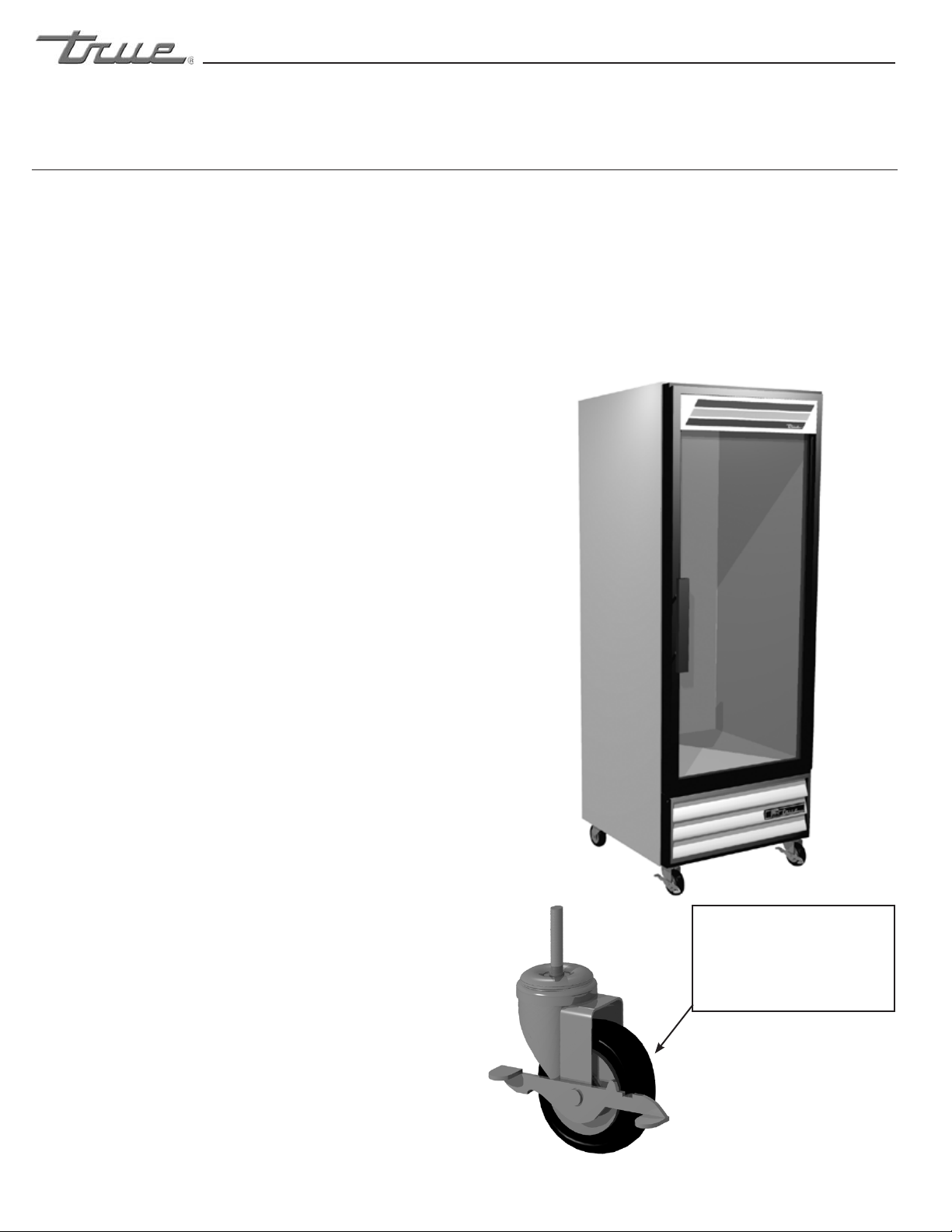
LEVELING
P
NEPCO/CENTRALAB
1227-5
REMOVECOVERMAKEPOWERCONNECTION
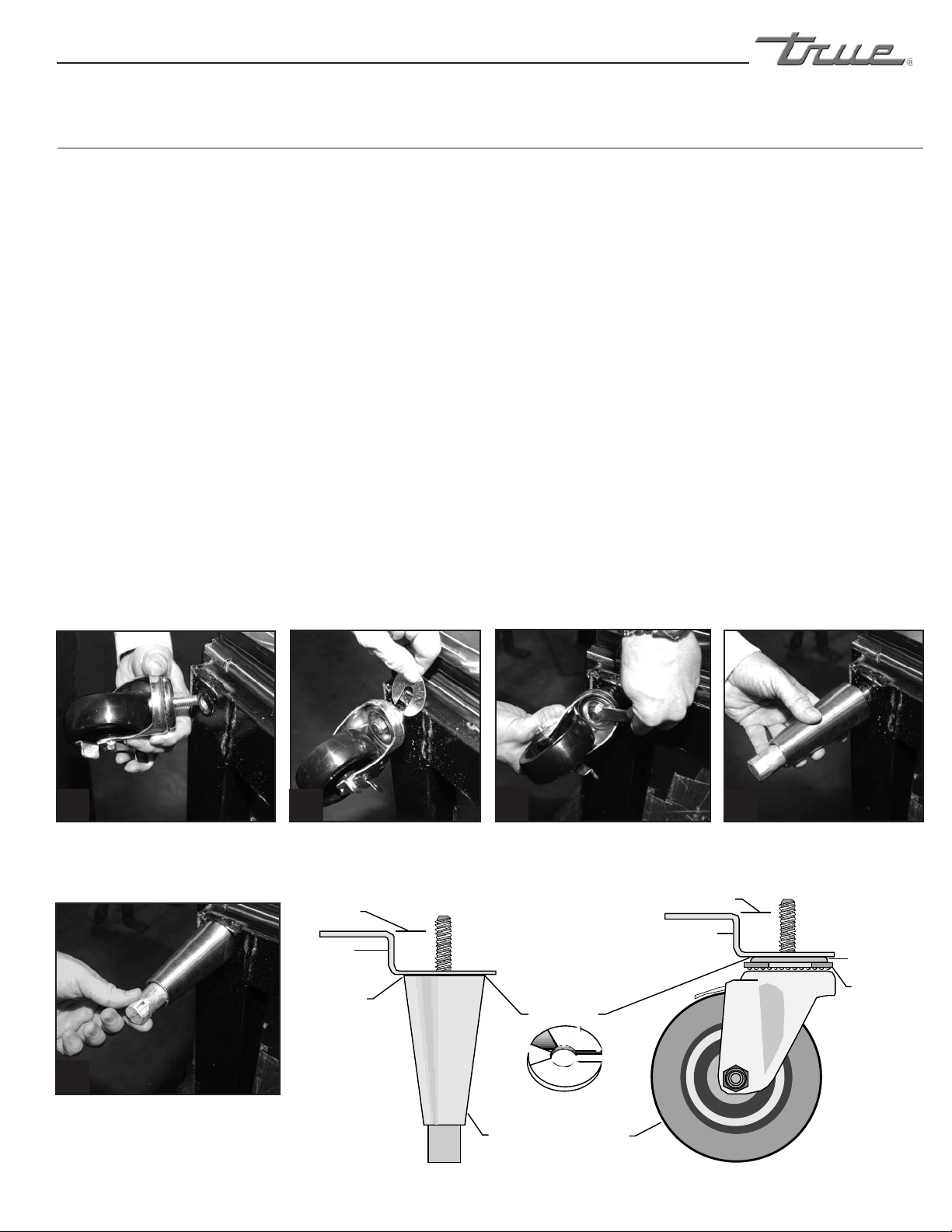
A. Removelouverfromthefrontofcabinetandbackguard
(ifapplicable)fromrearofcabinet(seepage29).
B. Skidboltsarelocatedineachof4cornersinsidecabinet
bottom.(SeephotoA).
C. Removeskidbolts.(SeephotoB).
D. Cutstrapsifapplicable.(SeephotoC).
E. Carefullyliftcabinetoffofskid. Removing skid from bottom of
cabinet.
AB
C
CLEARANCES (For proper cabinet operation, clearance guidelines should be followed)
Refrigerators – 1” at the rear, 0” at the sides, and open at the top (GDM-5, -6, -7, -9 = 1” at the rear, 1” at the sides,
and open at the top).
Freezers – 3” at the rear, 0” at the sides, and open at the top.
WARNING: Be sure there is adequate ventilation in your room. Under extreme heat conditions, (100°F+, 38°C+), you may
want to install an exhaust fan.