True TRM4M-BLK-WHT1-BLKLLLL-NY-4 User manual

TEC_TM_180 | REV. D | EN 12/11/2023 Page 1 of 44
RETAIL MERCHANDISER
OWNER'S MANUAL
TRUE MANUFACTURING CO., INC.
North America – Canada
and Caribbean
Warranty Phone: +1 855 878 9277
Warranty Fax: +1 636 980 8510
Technical Phone: +1 855 372 1368
Warranty Email:
Technical Email:
7:00 – 6:00 CST Monday – Friday.
8:00 – 12:00 Saturday.
Mexico
Phone: +52 555 804 6343/44
service-[email protected]om
9:00 am – 5:30 pm M–F
Latin America
Phone: +52 555 804 6343/44
9:00 am – 5:30 pm M–F
UK, Ireland, Middle East,
Africa and India
Phone: +44 (0) 800 783 2049
service-[email protected]
8:30 am – 5:00 pm M–F
European Union and
Commonwealth of
Independent States
Phone: +41 61 563 0705
service-[email protected]
8:00 am – 5:00 pm M–F
Australia
Phone: +61 2 9618 9999
8:30 am – 5:00 pm M–F
INSTALLATION MANUAL
RETAIL MERCHANDISER
Original Instructions
TRUE MANUFACTURING CO., INC.
2001 East Terra Lane • O’Fallon, Missouri 63366-4434
(636) 240-2400 • FAX (636)-272-2408
International FAX (636)272-7546 • (800)-325-6152
Parts Department (800)-424- TRUE
Parts Department FAX (636)-272-9471
842860-D
TRM4M-BLK-WHT1-BLKLLLL-NY-4 TRM3M-BLK-WHT-1BLKLLL-YN-4
USER ACTION!
TRUE tracks the history of your appliance by its serial number.
For easy reference, record your appliances full model name and
serial number below. This information is on your serial label.
Serial label location varies by appliance.
Model Name:
Serial Number:
WARNING!
Be sure to read and fully understand this document
before installing, operating, maintaining or servicing
this appliance. Failure to do so can result in appliance
failure, property damage, serious injury or death.
Appliance failure, injury or property damage due to
improper installation is not covered by warranty.

TEC_TM_180 | REV. D | EN
P#84286012/11/2023Page 2 of 44
RETAIL MERCHANDISER www.truemfg.com
THANK YOU
FOR YOUR PURCHASE
Preface
Signal & Symbol Definitions..............................................................3
Important Safety Information
Signal & Symbol Definitions..................................................3
Basic Safety & Operation Warnings ....................................4
Personal Injury Warnings........................................................5
Hydrocarbon Refrigerant Warnings....................................6
Appliance Disposal Warnings ...............................................6
Electrical Safety Warnings......................................................7
About Your Appliance & Installation Requirements
Appliance Specifications ........................................................7
Clearances....................................................................................7
Electrical Requirements ..........................................................8
Installation & Setup
Shelf Adjustment.................................................................... 15
Appliance Operation
Startup........................................................................................ 16
Temperature Control & Light Switch Location............ 17
General Sequence of Operation....................................... 18
Electronic Temperature Control Operation
Display Code Definitions..................................................... 19
Lock/Unlock the Control...................................................... 20
Turn Off/On the Control....................................................... 20
View & Change the Set Point............................................. 21
Initiate Manual Defrost ........................................................ 21
Change Display Readout..................................................... 22
Change Displayed Probe Temperature .......................... 23
Maintenance & Servicing
Component Replacement................................................... 25
Recommended Maintenance ........................................... 26
Condenser Coil Cleaning..................................................... 28
General Surface Care & Cleaning ..................................... 30
Stainless Steel Care & Cleaning......................................... 31
8 Tips to Help Prevent Rust on Stainless Steel............. 32
Door Adjustments & Reversal............................................ 33
Optional Acessories
Heated Drain Pan (HDP)....................................................... 39
Warranty
Warranty .................................................................................... 42
Congratulations!
The primary purpose of this document is to assist the installation, maintenance, and servicing of your TRUE
appliance. This document contains information important to safety, operation, maintenance, and servicing. DO NOT
discard this document. TRUE is solely the appliance manufacturer. For assistance finding a qualified technician, please
visit our Service Company Locator at truemfg.com/support/service-locator.
NOTICE!
Your appliance may not exactly match the figures shown in this manual.
Contents

TEC_TM_180 | REV. D | EN 12/11/2023 Page 3 of 44
RETAIL MERCHANDISER www.truemfg.com
Preface
The warning, guidelines, and recommendations within this document are meant to prevent appliance damage, injury, or death. Please
carefully read all warnings, guidelines, and recommendations before proceeding to ensure the continued safe use and maintenance of
your TRUE appliance.
Signal & Symbol Definitions
Below are symbols you may see in this document. Some symbols may not appear.
Signal Word Definitions
DANGER! An imminently hazardous situation which, if not avoided, will result in serious injury or death.
WARNING! A potentially hazardous situation which, if not avoided, can result in serious injury or death.
CAUTION! A potentially hazardous situation which, if not avoided, may result in minor or moderate injury;
an unsafe practice.
USER ACTION! User action alert, follow all recommendations to avoid appliance or product damage.
NOTICE! Important information not related to hazards or risk of personal injury.
Safety Symbols
Safety alert; alerts reader to potential physical
injury hazards. Obey all safety messages following
this symbol to avoid possible injury or death.
Flammable material; fire hazard.
Electrical shock hazard.
Tipping hazard; tip-over hazard.
Sharp element; cut or sever hazard.
Eye hazard; risk of eye injury.
Exploding pressurized cylinder hazard.
Slippery surface hazard.
Crush or cut hazard.
Additional Symbols
Mandatory action alert symbol; alerts reader
to required or recommended actions. Obey all
messages and recommendations following this
symbol to avoid appliance or product damage.
NOTICE ›Important information not related to hazards or
risk of personal injury.
Review and understand the installation manual
before installing, operating, or servicing.
Wear eye protection.
Wear protective gloves.
Secure gas cylinders to prevent falling cylinders.
DO NOT use extension cord.
DO NOT use adaptor plugs.
DO NOT dispose of with other household waste.

TEC_TM_180 | REV. D | EN
P#84286012/11/2023Page 4 of 44
RETAIL MERCHANDISER www.truemfg.com
WARNING!
Be sure to read and fully understand this document before installing, operating, maintaining, or servicing this appliance.
Failure to do so can result in appliance failure, property damage, serious injury, or death. Appliance failure, personal
injury, or property damage due to improper installation is not covered by warranty.
• Failure to install, operate, and maintain the appliance as detailed in this document will negatively affect safety, appliance
performance, component life, and warranty coverage.
• The appliance must be installed in accordance with all applicable laws, codes, and regulations.
• The manufacturer cannot be held responsible for injury or damage resulting from improper, incorrect, and unreasonable
use.
• This appliance is not to be used, cleaned, or maintained by persons (including children) with reduced physical, sensory, or
mental capabilities or lack of experience and knowledge, without proper supervision or instruction.
• DO NOT install or operate equipment that has been misused, abused, neglected, damaged, or altered/modified from
original manufactured specifications.
• DO NOT modify or alter the appliance. Improper alterations can result in electric shock, personal injury, fire, or death.
• DO NOT use electrical appliances inside the food storage compartments of the units unless the appliances are approved by
the manufacturer.
• The appliance owner is responsible for performing a Personal Protective Equipment (PPE) Hazard Assessment and to ensure
adequate protection during maintenance and cleaning procedures.
• Use appropriate tools, safety equipment, and PPE during installation and servicing.
• Only use the appliance for its intended purpose as described in this document. Failure to do so may result in equipment
damage, personal injury, or death.
• Overloading, incorrectly installing, or improperly loading shelves can cause shelf failure (as well as negatively affect the
appliance's operation), resulting in appliance damage, product damage, or personal injury.
• Keep the area surrounding the appliance clean to avoid appliance damage from debris or pests.
Important Safety Information
Basic Safety & Operation Warnings
Follow basic safety precautions, including the following, to reduce risk of personal injury, electric shock, fire, or death.
Important Safety Information

TEC_TM_180 | REV. D | EN 12/11/2023 Page 5 of 44
RETAIL MERCHANDISER www.truemfg.com
DANGER!
DO NOT allow children to play with or in the appliance. Child entrapment or personal injury can occur.
DO NOT store or use the following in the vicinity of this or any other appliance:
• Gasoline or other flammable vapors and liquids
• Combustible or explosive substances, such as aerosol cans with a flammable propellant
• Other volatile or flammable substances
Contact TRUE Manufacturing to locate refrigerant lines and electrical wiring before drilling, cutting or puncturing interior
or exterior walls. Failure to do so could result in damage, personal injury, or death.
WARNING!
Only qualified technicians should install and service the appliance.
• Use appropriate tools, safety equipment, and personal protective equipment (PPE) during installation and servicing.
• DO NOT touch the cold surfaces in the freezer compartment when hands are damp or wet. Skin may stick to extremely cold
surfaces.
This product can expose you to chemicals including Di-(2-Ethyl hexyl) Phthalate (DEHP), which is known to the State of
California to cause cancer and birth defects or other reproductive harm. For more information go to P65warnings.ca.gov.
Slippery Surfaces! Moisture from improper drainage can create slippery surfaces near the appliance. It is your duty to
immediately warn your customers of, and dry, the slippery surface. All wet floor areas must be marked with a wet floor sign.
Sharp edges! Take care when moving, installing, cleaning, servicing, and maintaining the appliance to avoid cuts. Be sure to
take care when reaching under the appliance or handling metal components.
• Keep fingers out of pinch point areas, such as the space between appliance doors and surrounding cabinetry. Take care
closing doors with children nearby.
Tip over hazard! Appliance may pose a tipping hazard when uncrating, installing, or moving the appliance. Take appropriate
safety precautions. Use of tip over restraints may only reduce (not eliminate) the tipping hazard. Never allow children to climb
or hang on drawers, doors, or shelves.
Crush or cut hazard! Keep clear when uncrating, installing, moving, or servicing the appliance.
Risk of electric shock or burn! See "Electrical Safety Warnings" for more information.
Personal Injury Warnings
Only qualified technicians should install and service the appliance. For assistance finding a qualified technician, please visit our Service
Company Locator at truemfg.com/support/service-locator. TRUE is solely the appliance manufacturer and is not responsible for
installation.
Important Safety Information (cont.)

TEC_TM_180 | REV. D | EN
P#84286012/11/2023Page 6 of 44
RETAIL MERCHANDISER www.truemfg.com
DANGER!
Risk of fire or explosion! Flammable refrigerant used.
• All servicing and maintenance must be performed by qualified technicians. This is to minimize the risk of fire or personal
injury due to incorrect parts or improper service.
• Check the serial label to identify the appliance's refrigerant. Serial label location varies by model.
• DO NOT damage the refrigeration system during transportation and installation.
• If the appliance is damaged, verify the refrigeration system's integrity is not compromised before proceeding.
• Never use sharp objects or tools to remove ice or frost. DO NOT use mechanical devices to accelerate defrost.
• Dispose of in accordance with all applicable laws, codes, and regulations. Follow all safety precautions associated with
handling flammable refrigerant.
• DO NOT use electrical appliances inside the food storage compartments of the units unless the appliances are of the type
recommended by the manufacturer.
DANGER!
Risk of child entrapment!
Children can get trapped inside discarded appliances and suffocate. Never dispose
of your appliance without taking precautions to prevent child entrapment, even
if the appliance only sits unattended for a short period of time.
Child entrapment precautions include the following:
• Remove all doors (or drawers for drawer units).
• Leave all interior drawers and shelving in place to make climbing (and fitting)
inside the appliance more difficult.
Risk of fire or explosion! Flammable refrigerant and insulation used. Dispose of in accordance with all applicable laws, codes,
and regulations. Follow all safety precautions associated with handling flammable refrigerant and insulation.
DO NOT dispose of your appliance with household waste.
Hydrocarbon Refrigerant Warnings
TRUE appliances use hydrocarbon refrigerant (R-290/513A/600a). Check the serial label to identify the appliance's refrigerant. Serial label
location varies by model.
Appliance Disposal Warnings
Important Safety Information (cont.)

TEC_TM_180 | REV. D | EN 12/11/2023 Page 7 of 44
RETAIL MERCHANDISER www.truemfg.com
About Your Appliance & Installation Requirements
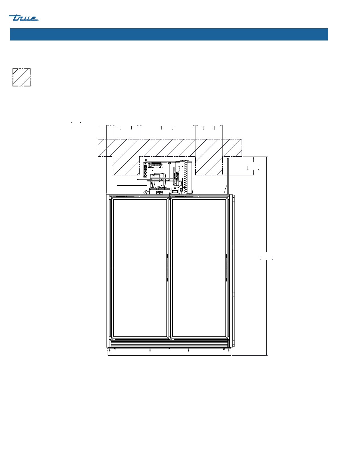
Model Side(s) Top Back
TRM Freezer 0" (0 mm) 6" (152.4 mm) 0" (0 mm)
TRM Refigerator 0" (0 mm) 6" (152.4 mm) 0" (0 mm)
Clearances
Be sure your unit has the required surrounding clearances for ventilation purposes. Keep all ventilation openings in the appliance enclosure
or structure housing the appliance clear of obstruction.
Thank you for choosing TRUE Manufacturing to meet your
refrigeration needs. TRUE highly recommends a qualified
technician and electrician install your appliance to ensure correct
installation. The cost of professional installation is money well
spent. Only qualified technicians should install and service the
appliance.
For assistance finding a qualified technician, please visit our Service
Company Locator at truemfg.com/support/service-locator. TRUE
is solely the appliance manufacturer and is not responsible for
installation.
The appliance owner is responsible for proper installation and
maintaining the appliance as described in this document. Routine
care and maintenance procedures are not covered by TRUE's
warranty.
About Your Appliance & Installation Requirements
USER ACTION!
TRUE is not responsible for damage incurred during
shipment. Always carefully inspect for freight damage
before receiving and installing your appliance. If
there is damage, note all damage on the delivery
receipt, immediately file a claim with the delivery
freight carrier, and contact TRUE. Do not install the
appliance or put it in service.
Appliance Specifications
Some things to know about your appliance are as follows:
• Appliance is not for the storage and/or display of potentially
hazardous foods when the temperature control is set above
41˚F (5˚C).
• Appliance is not suitable for outdoor use, unless otherwise
stated on the serial label.
• Appliance is not suitable for an area where a pressure washer
or hose may be used.
• Always plug the appliance into its own individual dedicated
electrical circuit!
• DO NOT use extension cords or adapter plugs.
• Before connecting your appliance to the power supply,
verify the incoming voltage (±5%) and the amps match the
operation ratings on the appliance's serial label. Correct
improper incoming voltage or amps immediately. Serial label
location varies by model.
• Before connecting your appliance to the power supply, verify
the power supply is correctly grounded. If the power supply
is not grounded, correct immediately.
• Ensure the installation location will provide adequate
clearances and sufficient airflow for the cabinet. See
"Clearances".
• Read and follow all warnings and maintenance instructions.
Failure to do so may result in damage and void the warranty
on your appliance.

TEC_TM_180 | REV. D | EN
P#84286012/11/2023Page 8 of 44
RETAIL MERCHANDISER www.truemfg.com
About Your Applicance & Installation Requirements (cont.)
Electrical Requirements Electrical Requirements
USER ACTION!
Find a copy of the wiring diagram with our serial
number lookup at
truemfg.com/support/serial-number-lookup
Each TRM requires one (1) individual dedicated circuit
See available locations for wall outlets by model in the
following diagrams.
Electrical Specifications
Model Power
Cord Voltage Frequency Phase Circuit Size
TRM2L L6-20P 208/240 V 60 Hz 120 amp
TRM2M L6-20P 208/240 V 60 Hz 120 amp
TRM3L L6-20P 208/240 V 60 Hz 120 amp
TRM3M L6-20P 208/240 V 60 Hz 120 amp
TRM4L L6-30P 208/240 V 60 Hz 130 amp
TRM4M L6-20P 208/240 V 60 Hz 120 amp
Wire gauge chart (115V)
115
Volts Distance in Feet to Center of Load
AMPS 20 30 40 50 60 70 80 90 100 120 140 160
214 14 14 14 14 14 14 14 14 14 14 14
314 14 14 14 14 14 14 14 14 14 14 12
414 14 14 14 14 14 14 14 14 12 12 12
14 14 14 14 14 14 14 12 12 12 10 10
614 14 14 14 14 14 12 12 12 10 10 10
714 14 14 14 14 12 12 12 10 10 10 8
814 14 14 14 12 12 12 10 10 10 8 8
914 14 14 12 12 12 10 10 10 8 8 8
10 14 14 14 12 12 10 10 10 10 8 8 8
12 14 14 12 12 10 10 10 8 8 8 8 6
14 12 12 12 10 10 10 8 8 8 6 6 6
16 12 12 12 10 10 8 8 8 8 6 6 6
18 12 12 10 10 8 8 8 8 8 8 8 5
20 12 12 10 10 8 8 8 6 6 6 5 5
25 10 10 10 8 8 6 6 6 6 5 4 4
30 10 10 8 8 6 6 6 6 5 4 4 3
Wire gauge chart (230V)
230
Volts Distance in Feet to Center of Load
AMPS 20 30 40 50 60 70 80 90 100 120 140 160
514 14 14 14 14 14 14 14 14 14 14 14
614 14 14 14 14 14 14 14 14 14 14 12
714 14 14 14 14 14 14 14 14 14 12 12
814 14 14 14 14 14 14 14 14 12 12 12
914 14 14 14 14 14 14 14 12 12 12 10
10 14 14 14 14 14 14 14 12 12 12 10 10
12 14 14 14 14 14 14 12 12 12 10 10 10
14 12 12 12 12 12 12 12 12 10 10 10 8
16 12 12 12 12 12 12 12 10 10 10 8 8
18 12 12 12 12 12 12 10 10 10 8 8 8
20 12 12 12 12 10 10 10 10 10 8 8 8
25 10 10 10 10 10 10 10 10 8 8 6 6
30 10 10 10 10 10 10 8 8 8 6 6 6
Fig. 1. NEMA plug configurations.
L6-20P L6-30P

TEC_TM_180 | REV. D | EN 12/11/2023 Page 9 of 44
RETAIL MERCHANDISER www.truemfg.com
About your Appliance & Installation Requirements
102 1/2"
2604mm
58 1/2"
1486mm
FOR "Y" SIDE
59 1/2" FOR "N" SIDE
[1511 mm]
3 1/2"
89mm
9 1/2"
241mm
TRM2L - OUTLET LOCATION 02/27/23
Electrical Requirements
= Potential Wall
Outlet Location
TRM2L Outlet Location

TEC_TM_180 | REV. D | EN
P#84286012/11/2023Page 10 of 44
RETAIL MERCHANDISER www.truemfg.com
TRM2M Outlet Location
About your Appliance & Installation Requirements (cont.)
102 1/2"
2604mm
9 1/2"
241mm
3"
76mm
FOR "Y" SIDE
4" FOR "N" SIDE
[101mm]
14"
356mm
29"
737mm
14"
356mm
TRM2M - OUTLET LOCATION 02/27/23
= Potential Wall
Outlet Location

TEC_TM_180 | REV. D | EN 12/11/2023 Page 11 of 44
RETAIL MERCHANDISER www.truemfg.com
About Your Applicance & Installation Requirements (cont.)
3"
76mm
FOR "Y" SIDE
4" FOR "N" SIDE
[101mm]
11"
279mm
66"
1676mm
11"
279mm
9 1/2"
241mm
102 1/2"
2604mm
TRM3L/TRM3M - OUTLET LOCATION 02/27/23
TRM3L/TRM3M Outlet Location
= Potential Wall
Outlet Location

TEC_TM_180 | REV. D | EN
P#84286012/11/2023Page 12 of 44
RETAIL MERCHANDISER www.truemfg.com
9 1/2"
241mm
102 1/2"
2604mm
3"
76mm
FOR "Y" SIDE
4" FOR "N" SIDE
[101mm]
10"
254mm
99"
2515mm
10"
254mm
TRM4L - OUTLET LOCATION 02/27/23
TRM4L Outlet Location
About your Appliance & Installation Requirements (cont.)
= Potential Wall
Outlet Location

TEC_TM_180 | REV. D | EN 12/11/2023 Page 13 of 44
RETAIL MERCHANDISER www.truemfg.com
About your Appliance & Installation Requirements (cont.)
9 1/2"
241mm
102 1/2"
2604mm
3"
76mm
FOR "Y" SIDE
4" FOR "N" SIDE
[101mm]
14"
356mm
30"
762mm
25"
635mm
36"
914mm
13"
330mm
TRM4M - OUTLET LOCATION 02/27/23
TRM4M Outlet Location
= Potential Wall
Outlet Location

TEC_TM_180 | REV. D | EN
P#84286012/11/2023Page 14 of 44
RETAIL MERCHANDISER www.truemfg.com
Installation & Setup
WARNING!
The appliance owner is responsible for performing
a Personal Protective Equipment (PPE) hazard
Assessment and to ensure adequate protection during
maintenance and cleaning procedures.
Use appropriate tools, safety equipment, and PPE
during installation and servicing.
Sharp edges! Take care when moving, installing,
cleaning, servicing and maintaining the appliance to
avoid cuts. Be sure to take care when reaching under
the appliance or handling metal components. Keep
fingers out of pinch point areas, such as the space
between appliance doors and surrounding appliances.
Take care closing doors with children nearby.
WARNING!
Risk of electrical shock or burn! Powering off an
electronic control or setting temperature controls to
the 0 (off) position does not remove power from all
components. Unplug the appliance or turn off the
power supply before installation or servicing.
Tip over hazard! Appliance may pose a tipping hazard
when uncrating, installing or moving the appliance.
Take appropriate safety precautions. Use of tip over
restraints may only reduce (not eliminate) the tipping
hazard. Never allow children to climb or hang on
drawers, doors or shelves.
Crush or cut hazard! Keep clear when uncrating,
installing, moving, or servicing the appliance.

TEC_TM_180 | REV. D | EN 12/11/2023 Page 15 of 44
RETAIL MERCHANDISER www.truemfg.com
Installation & Setup (cont.)
1. Remove the shelf shipping bracket, shelf cable ties, and
shipping tape. See figs. 2 and 3.
2. Lift the shelf assembly and then pull the shelf assembly
forward. See fig. 4.
3. Hook the shelf assembly into the shelf standards at the desired
height.
4. Repeat steps 1-3 for the remaining shelves.
Fig. 1. Plugging (A) and capping (B) a leveling leg hole.
Fig. 3. Shelf cable ties and shipping tape. Not all cable ties or tape shown.
Shelf Adjustment
Fig. 2. Shelf shipping bracket location. One bracket shown.
Fig. 4. Lift the shelf and pull forward.
A
A
B
B
USER ACTION!
DO NOT adjust shelving until AFTER the installation
process is complete. Foam cylinders and caps MUST
be installed in the leveling leg holes. See fig 1. Please
see installation packet for more details

TEC_TM_180 | REV. D | EN
P#84286012/11/2023Page 16 of 44
RETAIL MERCHANDISER www.truemfg.com
Appliance Operation
• The compressor is ready to operate when the appliance is
purchased. All you need to do is plug in the appliance.
• Good air flow inside your TRUE appliance is critical. Take care
to prevent product from pressing against the sides or back
wall and coming within 4" (101.6 mm) of the evaporator
housing. Refrigerated air off the evaporator coil must circulate
throughout the appliance for even product temperatures.
• Excessive tampering with the control could lead to service
difficulties. If replacing the temperature control is ever
needed, be sure to order the replacement from your TRUE
dealer or recommended service agent.
• All covers and access panels must be in place and properly
secured before operating this appliance.
Startup
Appliance Operation
USER ACTION!
Before loading product, run your TRUE appliance
empty for 24 hours to verify proper operation.
Remember, our factory warranty DOES NOT cover
product loss!
WARNING – SPOILAGE!
The owner is solely responsible for
ensuring safe holding temperature
levels for all food items. Failure to do so
may result in unsafe food products. Loss or spoilage
of products in your appliance is not covered by
warranty. In addition to following recommended
installation procedures, run the appliance for 24 hours
prior to usage to verify operation.

TEC_TM_180 | REV. D | EN 12/11/2023 Page 17 of 44
RETAIL MERCHANDISER www.truemfg.com
Appliance Operation (cont.)
Light Switch
In the front right ceiling.
Electronic Temperature Controls
In the front shroud; quantity varies by model
Temperature Control & Light Switch Location

TEC_TM_180 | REV. D | EN
P#84286012/11/2023Page 18 of 44
RETAIL MERCHANDISER www.truemfg.com
Appliance Operation (cont.)
General Sequence of Operation — Refrigerator and Freezer Appliances
When the appliance is plugged in:
• Interior lights will illuminate on glass door models (see Temperature Control & Light Switch location, pg. 17).
• An electronic control with digital display will illuminate (if installed).
• There may be a short delay before the compressor and/or evaporator fan(s) start. This delay may be determined by time or by
temperature, which could be the result of an initial defrost event that will last at least 6 minutes.
• The temperature control/thermostat may cycle the compressor and evaporator fan(s) on and off together. Every appliance will
require a defrost event to ensure the evaporator coil remains clear of frost and ice buildup. Defrost is initiated by a defrost timer
or by the electronic control.
EXCEPTION – Models TSID, TDBD, TCGG, and TMW do not have an evaporator fan(s).
• The temperature control/thermostat senses either an evaporator coil temperature or air temperature, NOT product temperature.
• An analog thermometer, digital thermometer, or electronic control display may reflect the refrigeration cycle swings of up and
down temperatures, NOT product temperature. The most accurate method to determine a appliance's operation is to
verify the product temperature.
• Refrigerators with mechanical temperature controls will defrost during every compressor off-cycle.
• Freezers with mechanical temperature controls will defrost by time initiation as determined by a defrost timer.
EXCEPTION – Models TFM, TDC, THDC and TMW require a manual defrost. The frequency of this manual defrost will depend on
the appliance's usage and ambient conditions.
• An electronic control with a digital display (if installed) will show dEF during defrost.
NOTICE ›The display may have a short delay before showing a temperature after a defrost event has expired and instead
show dEF during a refrigeration cycle.
• Models with an analog or digital thermometer may show higher than normal temperatures during defrost.
• A refrigerator will use the evaporator fans to clear the coil during defrost.
EXCEPTION – Models TSID, TDBD, and TCGG do not have an evaporator fan(s).
• A freezer will use heaters to clear the evaporator coil during defrost.
NOTICE ›The evaporator coil heater and drain tube heater are only energized during defrost. Defrost is terminated when a
specific evaporator coil temperature is reached or by a time duration.
USER ACTION!
For more information regarding a appliance's temperature control adjustment or general sequence of operation,
please see our Temperature Control Adjustment—Sequence of Operation Manual in our resource library at
truemfg.com/service-manuals/sequence-of-operation or scan the QR code.

TEC_TM_180 | REV. D | EN 12/11/2023 Page 19 of 44
RETAIL MERCHANDISER www.truemfg.com
Electronic Temperature Control Operation
dA Door switch alarm
dEF Defrost in progress
EE Data or memory failure
HA Maximum temperature alarm
LA Minimum temperature alarm
oFF Controller in stand-by
P1 Thermostat probe failure
P2 Evaporator probe failure
P3 Auxiliary probe failure
PoF Control is locked
Pon Control is unlocked
Display Code Definitions

TEC_TM_180 | REV. D | EN
P#84286012/11/2023Page 20 of 44
RETAIL MERCHANDISER www.truemfg.com
Electronic Temperature Control Operation (cont.)
Lock/Unlock the Control
Press and hold both the up and down arrows until the
display shows PoF (locked) or Pon (unlocked).
Turning off the control deactivates all electronic
components connected to the control.
Push and hold the power button until the display
shows OFF (stand-by) or the current appliance
temperature (powered).
SET
°C
°F
C
F
AUX
AUX
ECO
SET
°C
°F
C
F
AUX
AUX
ECO
SET
°C
°F
C
F
AUX
AUX
ECO
Turn Off/On the Control
SET
°C
°F
C
F
AUX
AUX
ECO
WARNING!
Risk of electric shock or burn!
Powering off an electronic control or
setting temperature controls to the 0 (off)
position does not remove power from all
components. Unplug the appliance or turn
off the power supply before installation or
servicing.
This manual suits for next models
1
Table of contents
Other True Merchandiser manuals
Popular Merchandiser manuals by other brands

Howard McCray
Howard McCray R-CMS32E-4 Specifications

Hussmann
Hussmann G5 install guide

Structural Concepts
Structural Concepts Reveal NR3651RRSSV Installation and operating manual

Hussmann
Hussmann ASC-LG Installation and operation guide

Hatco
Hatco FLAV-R-SAVOR FSHC-6W1 Installation and operating manual

Hussmann
Hussmann VGK install guide