manuals.online logo
Brands
  1. Home
  2. •
  3. Brands
  4. •
  5. LEGRAND
  6. •
  7. Controllers
  8. •
  9. LEGRAND Wattstopper DCLV2 Service manual

LEGRAND Wattstopper DCLV2 Service manual

Other manuals for Wattstopper DCLV2

1

Other LEGRAND Controllers manuals

LEGRAND Pass & Seymour LightSense PSHCF User manual

LEGRAND

LEGRAND Pass & Seymour LightSense PSHCF User manual

LEGRAND MRD6 v2 User manual

LEGRAND

LEGRAND MRD6 v2 User manual

LEGRAND Celiane 670 89 User manual

LEGRAND

LEGRAND Celiane 670 89 User manual

LEGRAND 0 884 07 User manual

LEGRAND

LEGRAND 0 884 07 User manual

LEGRAND Arteor 5 742 07 User manual

LEGRAND

LEGRAND Arteor 5 742 07 User manual

LEGRAND HA7000 User manual

LEGRAND

LEGRAND HA7000 User manual

LEGRAND 0 676 46 User manual

LEGRAND

LEGRAND 0 676 46 User manual

LEGRAND 5739 12 Instruction Manual

LEGRAND

LEGRAND 5739 12 Instruction Manual

LEGRAND 0 484 22 User manual

LEGRAND

LEGRAND 0 484 22 User manual

LEGRAND PRO 21 7756 22 User manual

LEGRAND

LEGRAND PRO 21 7756 22 User manual

LEGRAND radiant User manual

LEGRAND

LEGRAND radiant User manual

LEGRAND Wattstopper DCLV2 User manual

LEGRAND

LEGRAND Wattstopper DCLV2 User manual

LEGRAND Celiane Series Quick start guide

LEGRAND

LEGRAND Celiane Series Quick start guide

LEGRAND EasyIP VADDIO PCC User manual

LEGRAND

LEGRAND EasyIP VADDIO PCC User manual

LEGRAND ADMHRM4 User manual

LEGRAND

LEGRAND ADMHRM4 User manual

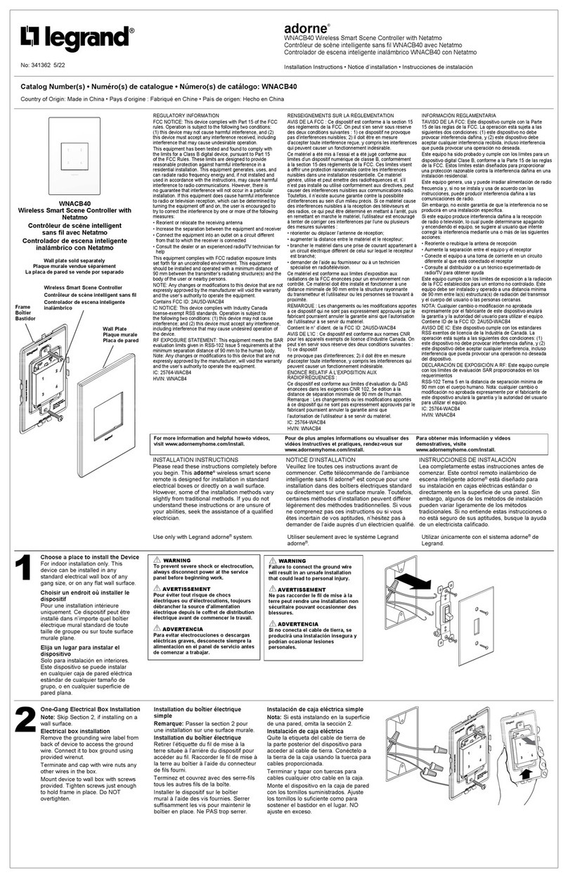
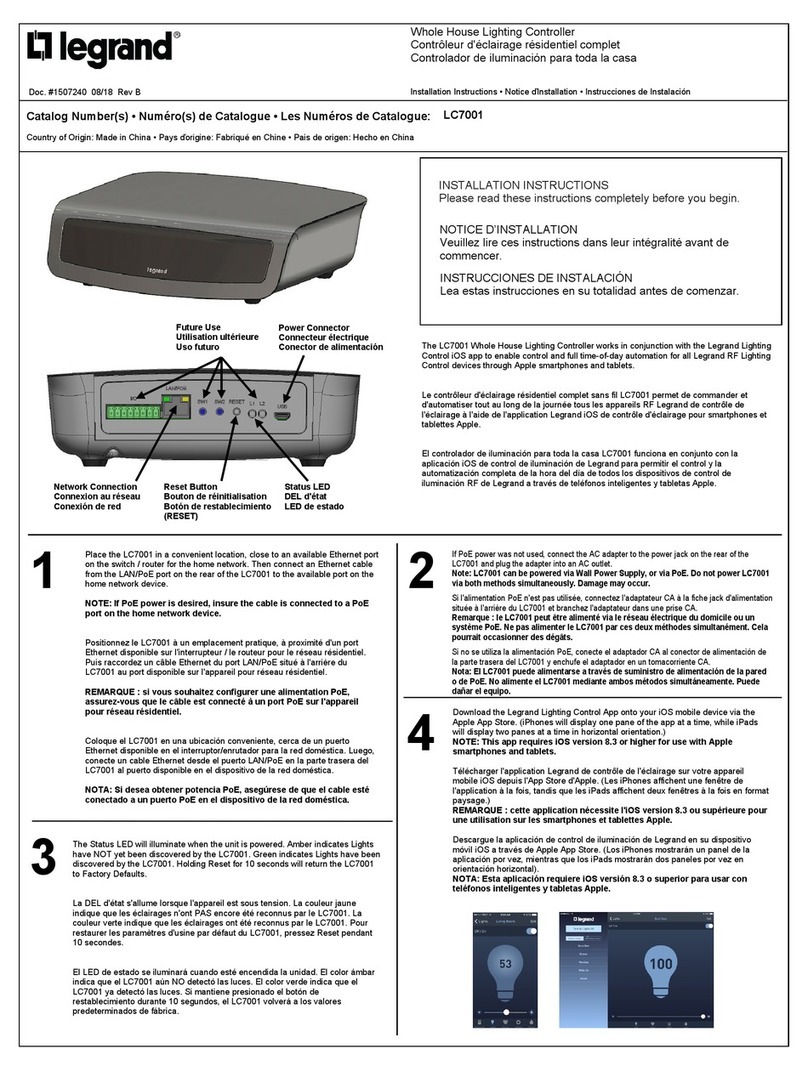
LEGRAND Adorne LC7001 User manual

LEGRAND

LEGRAND Adorne LC7001 User manual

LEGRAND Wattstopper LMJA-8125-SM User manual

LEGRAND

LEGRAND Wattstopper LMJA-8125-SM User manual

LEGRAND Bticino H4652 User manual

LEGRAND

LEGRAND Bticino H4652 User manual

LEGRAND 0 766 22 User manual

LEGRAND

LEGRAND 0 766 22 User manual

LEGRAND 5739 04 Instruction Manual

LEGRAND

LEGRAND 5739 04 Instruction Manual

LEGRAND Wattstopper LMRC-611MCC User manual

LEGRAND

LEGRAND Wattstopper LMRC-611MCC User manual

LEGRAND 0 663 37 User manual

LEGRAND

LEGRAND 0 663 37 User manual

LEGRAND 0 698 74L User manual

LEGRAND

LEGRAND 0 698 74L User manual

LEGRAND ON-Q LC6400 User manual

LEGRAND

LEGRAND ON-Q LC6400 User manual

Popular Controllers manuals by other brands

Sunricher SR-ZV9003T3-RGBW-US Installation

Sunricher

Sunricher SR-ZV9003T3-RGBW-US Installation

Ksenia intro Installation and configuration manual

Ksenia

Ksenia intro Installation and configuration manual

Inovance CAN200 Series manual

Inovance

Inovance CAN200 Series manual

Gauzy LC6 FLEX Controller Installation and operation guide

Gauzy

Gauzy LC6 FLEX Controller Installation and operation guide

Viking SLP-1 Technical practice

Viking

Viking SLP-1 Technical practice

CKD KBX-30E-U Series instruction manual

CKD

CKD KBX-30E-U Series instruction manual

Sharp Energy Sun Flux User manual & installation guide

Sharp Energy

Sharp Energy Sun Flux User manual & installation guide

Yamaha RCX40 user manual

Yamaha

Yamaha RCX40 user manual

AB Quality PowerFlex 400 Frames D-H Service bulletin

AB Quality

AB Quality PowerFlex 400 Frames D-H Service bulletin

Yamaha MJC8 owner's manual

Yamaha

Yamaha MJC8 owner's manual

AL-KO ATC operating instructions

AL-KO

AL-KO ATC operating instructions

Savant SmartControl 2 Deployment guide

Savant

Savant SmartControl 2 Deployment guide

GameSir T3S user manual

GameSir

GameSir T3S user manual

Kostal inveor operating manual

Kostal

Kostal inveor operating manual

Emerson Yarway 20-55 Operating and safety instructions

Emerson

Emerson Yarway 20-55 Operating and safety instructions

CoCo ACM-LV24 Quick installation guide

CoCo

CoCo ACM-LV24 Quick installation guide

Brooks SLA5810/20 Installation and operation manual

Brooks

Brooks SLA5810/20 Installation and operation manual

SIGMA TEK SR 011 Technical manual

SIGMA TEK

SIGMA TEK SR 011 Technical manual

manuals.online logo
manuals.online logoBrands
  • About & Mission
  • Contact us
  • Privacy Policy
  • Terms and Conditions

Copyright 2025 Manuals.Online. All Rights Reserved.

Wattstopper
®
Decorator Style 0-10V Controller
Installation Instructions • Instructions d’Installation • Instrucciones de Instalación
No: 27465 – 06/18 rev. 2
Catalog Number • Numéro de Catalogue • Número de Catálogo: DCLV2
Country of Origin: Made in China • Pays d’origine: Fabriqué en Chine • País de origen: Hecho en China
SPECIFICATIONS
Power Supply .......................................Wattstopper Power Pack
Rating .............................................................. 24VDC, 16mA
Control outputs
For 0–10V Dimming Ballasts:
Sink ................................................................up to 50mA
Maximum voltage.................................................9.5VDC
Minimum voltage................................................0.75VDC
Operating Temperature ....................... 32° to 104°F (0° to 40°C)
DESCRIPTION
The DCLV2 0–10V dimming wallbox controller includes a Manual On feature or partial Auto On.
The DCLV2 must be used with BZ Series power packs and can be combined with occupancy sensors.
Features
• Control electronic ballasts and drivers for LED systems.
• Sink up to 50mA, allowing the product to control up to 100 ballasts wired in parallel (each ballast sourcing 0.5mA).
• 0–10V output ranges at a minimum between 0.75VDC and 9.5VDC.
• Able to receive a sensor input.
• Operating supply voltage 24VDC: Class-2 device powered directly from an external source.
• Wattstopper BZ series for 0-10V ballast control.
INSTALLATION
NOTE: INSTALL IN COMPLIANCE WITH ALL APPLICABLE CODES & STANDARDS.
Failure to follow these instructions may cause personal injury or equipment damage.
The DCLV2 is a Class 2 product. A low voltage cable with the appropriate number of conductors must be installed. For ease of
installation, manufacturer recommends use of a deep wall box.
1. Disconnect power to circuit by turning circuit breaker OFF before installation.
2. Remove the existing wall plate and switch, if one is present. If there is an existing line voltage switch the wiring must be converted
to low voltage in order to use the original wall box location for the DCLV2. Alternatively, the existing line voltage switch may
remain, however a new wall box must be installed for the DCLV2 according to NEC requirements.
3. Install power pack to control the desired lighting circuit.
4. Strip existing wires 1/4”. If two wires will be connected to the same terminal, both wires must be the same gauge. Connect wires
as appropriate for your application. See the wiring diagrams on the following page.
5. Attach the wall plate.
6. Switch the circuit breaker back ON.
2
WARNING: TURN THE POWER OFF AT THE
CIRCUIT BREAKER BEFORE INSTALLING
THE DEVICE OR POWER/SLAVE PACKS.
LOAD TYPES
Use the DCLV2 for these load types:
• 0 to 10V electronic dimming ballasts (Mark 7 or equivalent)
with maximum of up to 50mA.
• Compatible LED systems (verify compatibility with LED control
manufacturer).
TERMINAL BLOCK
The DCLV2 has a wiring terminal block with 7 positions:
124VDC input
2Common
30–10V Violet
4Sensor input
5Control Output
60–10V Gray
7Common
DIMMING MODE
The DCLV2 supports low-voltage DC dimming, using Class 2
wires. Multiple circuits can use the same dimming signal without
additional power equipment.
0–10V Dimming curves
To accommodate various types of ballasts, the DCLV2, executes
a straight proportional relationship between the internal level and
the voltage provided, 0.6VDC to 9.5VDC.
0–10V Dimming (with ON/OFF option)
• When the user ramps up, relay 1 output
switches from 0V to 24VDC. This closes
the power pack relay to supply line
voltage to the light fixtures.
• When the user ramps down and the
0–10V output becomes 0V, relay 1
switches to 0V. This opens the power
pack relay to remove power to the
light fixtures. This allows the ballast to
smoothly ramp down and then be turned
OFF.
NOTE: An ON to OFF transition can take
longer than expected (by about 2
seconds) because the DCLV2 is
dimming down. The OFF to ON
transition is immediate.
WIRING EXAMPLES, LIGHTING CONTROL
Neutral
Hot
White
Black Red
Red
Fixture
**Ground
Red
Black
Blue
Orange
Brown
Gray
Low Voltage Wires
24VDC
0–10V
Control
0–10V
Common
Red
VioletGray
Black
Power Pack
BZ Series
DCLV2
Blue
Sensor
Blue
0-10V wiring diagram
Neutral
Hot
White
Black Red
Red
Fixture
Sensor
Ceiling/Wall
24VDC
Any
**Ground
Red
Black
Blue
Orange
Brown
Gray
Low Voltage Wires
24VDC
0–10V
Sensor
Control
0–10V
Ground
Common
Red
VioletGray
Black
Black
Control Output
+24VDC
Red
Common
Power Pack
BZ Series
DCLV2
Blue
Blue
Blue
Sensor input wiring diagram
Ballast ON/OFF control wiring diagram
To control a simple ON/OFF system do not connect the 0-10V output on
the DCLV2.
Neutral
Hot
White
Black Red
Red
Fixture
**Ground
Red
Black
Blue
Orange
Brown
Gray
Low Voltage Wires
24VDC
Control
Common
Red
Black
Power Pack
BZ Series
DCLV2
Blue
Sensor
Blue
',00(5%27720),1*(5
'&2',00(5723),1*(5
NOTES
Any BZ series power pack will work with the DCLV2, but the
following should be noted
• The Orange, Brown, and Gray wires on the BZ-150 and
BZ-250 are not used and should be capped
• The Manual/Auto On switch on the BZ-150 and BZ-250
should be left in the Auto-On position. Manual functionality is
handled by the DCLV2.
• The BZ-200 and BZ-250 must be grounded to ensure signal
integrity,not for safety ground.
3
SETTING THE OPERATING MODE
By default, Manual On mode is enabled. Auto On is disabled.
To enable Auto On mode:
1. Press and hold the top and bottom of the paddle for two seconds to enter LEARN
mode.
2. Release the paddle.
3. Press and hold RAISE for two seconds, until the device confirms the new mode by
flashing its LED red, for 1.5 seconds.
4. Press and hold LEARN again (for two seconds) to exit the setup/binding mode and
return to normal operation.
To switch back to Manual On mode:
1. Press and hold the top and bottom of the paddle for two seconds to enter LEARN
mode.
2. Release the paddle.
3. Press and hold LOWER for two seconds, until the device confirms by flashing its LED
green, for 1.5 seconds.
4. Press and hold LEARN again (for two seconds) to exit the setup/binding mode and
return to normal operation.
NOTE: For both Manual On and Auto On, if the top of the paddle is momentarily pressed
when the load is already ON, the load will go to 100%.
Partial On Mode
By default, when the sensor triggers occupancy, the DCLV2 will normally set the load to the dimming level that it was at when Manual
On or Auto On is enabled. This is referred to as Partial On. To set the fixed value for Partial On:
1. Press and hold the top and bottom of the paddle for two seconds to enter LEARN mode.
2. Release the paddle.
3. Use the paddle to set the desired dimming level for the fixed amount.
4. Press and hold LEARN again (for four seconds) to exit the setup/binding mode and return to normal operation.
NOTE: By default, or after a reset, Partial On is enabled with a fixed value of 50%.
To disable the Partial On feature:
1. Turn OFF the Load.
2. Press and hold the top and bottom of the paddle for two seconds to enter LEARN mode.
3. Release the paddle.
4. Press and hold LEARN again (for four seconds) to exit the setup/binding mode and return to normal operation.
Alternatively, you can use this second method to disable Partial On:
1. Press and hold the top and bottom of the paddle for two seconds to enter LEARN mode.
2. Release the paddle.
3. Press the bottom of the paddle till the load is off.
4. Press and hold LEARN again (for four seconds) to exit the setup/binding mode and return to normal operation.
Retrigger Mode
When in Manual On mode, and the connected sensor registers a vacancy and turns the load OFF, an automatic 30 second retrigger
mode is enabled. If the sensor registers occupancy, the load will return to its previous level. After the 30 second retrigger period, when
the sensor registers occupancy, the load will respond based on the Manual On or Auto On setting from the DCLV2.
Resetting to Factory Defaults
Facory default for the DCLV2 is Manual On with Partial On enabled at 50%. To reset:
1. Press and hold the top and bottom of the paddle for 10 seconds
2. The green LED will blink and the lights will turn off, inidicating the the reset is complete.
',00(5%27+),1*(56
'&2',00(5723),1*(5
',00(5%27720),1*(5
LEARN
LOWER
Green LED confirms
Manual On mode.
RAISE
Red LED confirms
Auto On mode.
800.879.8585
www.legrand.us/wattstopper
No. 27465 – 06/18 rev. 2
© Copyright 2018 Legrand All Rights Reserved.
© Copyright 2018 Tous droits réservés Legrand.
© Copyright 2018 Legrand Todos los derechos reservados.
Wattstopper warranties its products to be free
of defects in materials and workmanship for a
period of five (5) years. There are no obligations
or liabilities on the part of Wattstopper for
consequential damages arising out of, or in
connection with, the use or performance of this
product or other indirect damages with respect
to loss of property, revenue or profit, or cost of
removal, installation or reinstallation.
Wattstopper garantit que ses produits sont
exempts de défauts de matériaux et de fabrication
pour une période de cinq (5) ans. Wattstopper
ne peut être tenu responsable de tout dommage
consécutif causé par ou lié à l’utilisation ou
à la performance de ce produit ou tout autre
dommage indirect lié à la perte de propriété, de
revenus, ou de profits, ou aux coûts d’enlèvement,
d’installation ou de réinstallation.
Wattstopper garantiza que sus productos
están libres de defectos en materiales y mano
de obra por un período de cinco (5) años. No
existen obligaciones ni responsabilidades por
parte de Wattstopper por daños consecuentes
que se deriven o estén relacionados con el
uso o el rendimiento de este producto u otros
daños indirectos con respecto a la pérdida
de propiedad, renta o ganancias, o al costo
de extracción, instalación o reinstalación.
WARRANTY INFORMATION INFORMATIONS RELATIVES ÀLAGARANTIE INFORMACIÓN DE LAGARANTÍA