Trumpf HELION S User manual

XENION®HELION®Surgical Lighting System
Service Manual

7200791 Service Manual for the HELION®XENION®Surgical Lighting System GB
2
To the Service technician,
Please read through this service manual with great care and com-
ply with the safety information and requirements for servicing.
CE markingCE marking
CE markingCE marking
CE marking
This item of equipment is a Class I medical device as defined by
the European Medical Device Directive (MDD) 93/42/EEC, June
1993, Appendix IX.
The manufacturer declares that this product conforms to the fun-
damental requirements according to MDD Appendix I and docu-
ments this by means of the CE marking.
What equipment forms the subject of this service manual?What equipment forms the subject of this service manual?
What equipment forms the subject of this service manual?What equipment forms the subject of this service manual?
What equipment forms the subject of this service manual?
The surgical lighting system with the following variants:
• 1 to 4-fold suspension with the following types of lamp:
HELION®with halogen lamp:
• HELION S; HELION M/M+; HELION L/L+.
XENION®with metal vapour lamp:
• XENION M/M+; XENION L/L+.
And the following optional equipment:
• TFT flat screens 15“and 19“,
• HELION M/M+; L/L+; XENION M+ with fixed focus camera.
• TruVidia camera system.
TT
TT
Technical Customer Service is at your disposal,echnical Customer Service is at your disposal,
echnical Customer Service is at your disposal,echnical Customer Service is at your disposal,
echnical Customer Service is at your disposal,
• if you have any questions on disassembly, repairs or settings,
or
• if you would like to re-order spare parts.
How to contact usHow to contact us
How to contact usHow to contact us
How to contact us
• TRUMPF KREUZER Medizin Systeme GmbH + Co. KG
• Benzstrasse 26
• 82178 Puchheim, Germany
• Telephone: +49 / (0)89 / 8 09 07 - 0
• Fax: +49 / (0)89 / 8 09 07 - 2 22
• Telephone: +49 / (0) 180 / 2 25 41 35
• Fax: +49 / (0) 36 71 / 58 61 75
© TRUMPF KREUZER, 2004
• Edition: 03/2005, Version 1 (15.03.2005)
www.Trumpf-med.com
Conformity
Sales
Service
Visit us on the Internet

7200791 Service Manual for the HELION®XENION®Surgical Lighting System GB 3
• The information contained in this service manual and parts
thereof are the intellectual property of TRUMPF KREUZER
Medizin Systeme GmbH + Co. KG and is protected by na-
tional and international copyright and other laws for the pro-
tection of intellectual property.
• Any duplication, reproduction, translation, microfilming stor-
age - in either electronic or magnetic form - processing as
electronically or magnetically stored data, copying or distribu-
tion of these documents and/or the information contained
herein or parts thereof without the prior written approval of
TRUMPF KREUZER Medizin Systeme GmbH + Co. KG is hereby
strictly prohibited.
TRUMPF KREUZER Medizin Systeme GmbH + Co. KG shall
assume no liability whatsoever on the basis of, or in associa-
tion with, the use of said information prohibited in this manner
by any person or company.
• TRUMPF KREUZER Medizin Systeme GmbH + Co. KG reserves
the right to amend, delete or modify in any other manner all
information contained herein at any time and on any grounds
without prior notice.
We are constantly engaged on the further development of our
products and reserve the right to make changes to the scope
of supply in terms of design, equipment or technology.
• TRUMPF KREUZER Medizin Systeme GmbH + Co. KG explic-
itly reserves all rights under the copyright laws.
• The German-language version of this service manual shall be
binding as regards translations into foreign languages.
• The HELION®and XENION®lamps are registered trademarks
of TRUMPF KREUZER Medizin Systeme GmbH + Co. KG.
• All trademarks mentioned in this service manual are the sole
property of the respective manufacturers.
Notes relating to this documentation
Copyright
We reserve the right to
make changes
Copyrights
Translations
Trademarks

7200791 Service Manual for the HELION®XENION®Surgical Lighting System GB
4
Contents
11
11
1Important Information for the Service TImportant Information for the Service T
Important Information for the Service TImportant Information for the Service T
Important Information for the Service Technicianechnician
echnicianechnician
echnician ............
............
...... 88
88
8
1.1 Information for the service technician .......................... 8
1.2 Tools and equipment required .................................... 8
1.3 Proper servicing ........................................................ 9
1.4 Warranty and liability ................................................. 9
1.5 Disposal ................................................................... 9
22
22
2YY
YY
Your Safety is Important to Usour Safety is Important to Us
our Safety is Important to Usour Safety is Important to Us
our Safety is Important to Us ..............................................................
..............................................................
...............................1010
1010
10
2.1 Symbols used in this service manual ......................... 10
2.2 Symbols on the equipment ....................................... 10
2.3 Overview of the most important safety information ..... 11
33
33
3Observe these WObserve these W
Observe these WObserve these W
Observe these Work Rork R
ork Rork R
ork Rulesules
ulesules
ules........................................................................
........................................................................
.................................... 1313
1313
13
44
44
4TT
TT
Table - Table - T
able - Table - T
able - Troubleshooting and Proubleshooting and P
roubleshooting and Proubleshooting and P
roubleshooting and Possible Rossible R
ossible Rossible R
ossible Remediesemedies
emediesemedies
emedies............
............
......1414
1414
14
55
55
5Changing the LChanging the L
Changing the LChanging the L
Changing the Lampamp
ampamp
amp ..........................................................................................
..........................................................................................
............................................. 1717
1717
17
5.1 Changing the lamp of the HELION S ........................ 17
5.2 Changing the lamp of the HELION M/M+ / L/L+ ..... 17
5.3 Changing the lamp of the XENION M/M+ ............... 18
5.4 Changing the lamp of the XENION L/L+ .................. 19
66
66
6Setting the LSetting the L
Setting the LSetting the L
Setting the Luminous Fuminous F
uminous Fuminous F
uminous Fieldield
ieldield
ield ........................................................................
........................................................................
.................................... 2020
2020
20
6.1 Setting the luminous field for the
HELION M/M+ / L/L+ ........................................... 20
6.2 Setting the luminous field for the XENION M/M+ ...... 21
6.3 Setting the luminous field for the XENION L/L+ ......... 22
6.4 Setting the luminous field for the XENION M
with fixed focus camera ........................................... 22
77
77
7RR
RR
Replacing the Feplacing the F
eplacing the Feplacing the F
eplacing the Filter Glass Assemblyilter Glass Assembly
ilter Glass Assemblyilter Glass Assembly
ilter Glass Assembly ............................................
............................................
......................2323
2323
23
88
88
8TT
TT
Testing the Servomotor for theesting the Servomotor for the
esting the Servomotor for theesting the Servomotor for the
esting the Servomotor for the
HELION M/M+ L/L+HELION M/M+ L/L+
HELION M/M+ L/L+HELION M/M+ L/L+
HELION M/M+ L/L+ ....................................................................................
....................................................................................
.......................................... 2424
2424
24
8.1 Testing the polarity of the servomotor ........................ 24
8.2 Testing the servomotor ............................................. 25
99
99
9TT
TT
Testing the Input Vesting the Input V
esting the Input Vesting the Input V
esting the Input Voltagesoltages
oltagesoltages
oltages ..........................................................................
..........................................................................
..................................... 2626
2626
26
9.1 Testing the input voltage of the transformer ............... 26
9.2 Testing the mains fuse for the building
power supply .......................................................... 26

7200791 Service Manual for the HELION®XENION®Surgical Lighting System GB 5
Contents
1010
1010
10 TT
TT
Testing the Electrics of the Support Systemesting the Electrics of the Support System
esting the Electrics of the Support Systemesting the Electrics of the Support System
esting the Electrics of the Support System ..........................
..........................
.............2727
2727
27
10.1 Testing the voltage at the sliding contact in the extension
arm........................................................................ 27
10.2 Replacing the sliding contact in the extension arm/
Testing the slip ring on the central column ................. 28
10.3 Dismantling the light head ....................................... 29
10.4 Testing the cables in the spring arm that lead to the
contact block
in the extension arm ................................................ 29
10.6 Testing the cables in the extension arm...................... 30
10.7 Replacing the cables in the extension arm ................. 31
10.8 Dismantling the central column ................................ 31
10.9 Replacing the slip ring ............................................. 32
1111
1111
11 TT
TT
Testing the Electrics of theesting the Electrics of the
esting the Electrics of theesting the Electrics of the
esting the Electrics of the
HELION M / L LHELION M / L L
HELION M / L LHELION M / L L
HELION M / L Lampamp
ampamp
amp........................................................................................
........................................................................................
............................................ 3333
3333
33
11.1 Testing the voltage at the focus unit .......................... 33
11.2 Testing the voltages and cables in the lamp ............... 34
1212
1212
12 TT
TT
Testing the Electrics of theesting the Electrics of the
esting the Electrics of theesting the Electrics of the
esting the Electrics of the
HELION M+ / L+ LHELION M+ / L+ L
HELION M+ / L+ LHELION M+ / L+ L
HELION M+ / L+ Lampamp
ampamp
amp ............................................................................
............................................................................
...................................... 3636
3636
36
12.1 Testing the voltage at the focus unit .......................... 36
12.2 Testing the operating voltages, fuse and
cables in the lamp ................................................... 37
12.3 When the dimmer is defective .................................. 39
1313
1313
13 TT
TT
Testing the Electrics of theesting the Electrics of the
esting the Electrics of theesting the Electrics of the
esting the Electrics of the
XENION M/M+ / L/L+ LXENION M/M+ / L/L+ L
XENION M/M+ / L/L+ LXENION M/M+ / L/L+ L
XENION M/M+ / L/L+ Lampamp
ampamp
amp ............................................................
............................................................
..............................4040
4040
40
13.1 Testing the operating voltages, fuses and
cables in the lamp ................................................... 40
13.2 When the dimmer is defective .................................. 42
1414
1414
14 FF
FF
Functional Check, Hand-unctional Check, Hand-
unctional Check, Hand-unctional Check, Hand-
unctional Check, Hand-Over and CustomerOver and Customer
Over and CustomerOver and Customer
Over and Customer
InstructionInstruction
InstructionInstruction
Instruction ......................................................................................................................
......................................................................................................................
........................................................... 4343
4343
43
14.1 Important Information .............................................. 43
14.2 Inspection intervals and authorised staff .................... 43
14.3 Monitoring activities ................................................ 44
14.4 Testing the function of the lamps............................... 48

7200791 Service Manual for the HELION®XENION®Surgical Lighting System GB
6
15 T15 T
15 T15 T
15 Technical Descriptionechnical Description
echnical Descriptionechnical Description
echnical Description ....................................................................................
....................................................................................
.......................................... 5050
5050
50
15.1 Data sheets ............................................................ 50
15.2 Circuit diagrams and set values ................................ 52
15.2.1 HELION M/M+; HELION L/L+; HELION XL+ .. 52
15.2.2 XENION M/M+; XENION L/L+........................ 53
15.2.3 XENION M / M+ ............................................ 54
15.2.4 XENION L/L+ ................................................. 55
15.2.5 HELION M+; HELION L+
with wall control panel ..................................... 56
15.2.6 XENION M/M ; XENION L/L+
with wall control panel ..................................... 57
15.2.7 24 V power supply AC/DC HELION M/M+;
HELION L/L+ ; HELION XL+;
XENION M/M+; XENION L/L+........................ 58
15.2.8 TruVidia combination
with HELION M/M+; HELION L/L+; HELION XL+;
XENION M/M+; XENION L/L+ lamps ............... 59
15.2.9 7-pole plug -> cardanic suspension
TruVidia 8-pole DIN socket ............................... 60
15.2.10 5-pole plug TFT LCD monitor with cardanic suspen-
sion; (optional DC/DC converter) ...................... 61
15.2.11 TFT LCD monitor .............................................. 62
15.2.12 TFT LCD monitor
with monitor power supply unit .......................... 63
15.2.13 Plug connector -> TruVidia spring arm .............. 64
15.2.14 Plug connector -> spring arms
3-pole / 5-pole / 7-pole................................... 65
15.2.15 HELION M/L light head .................................... 66
15.2.16 HELION M/L light head
with fixed focus camera .................................... 67
15.2.17 HELION M/L light head
with TruVidia .................................................... 68
15.2.18 HELION M+/L+ light head .............................. 69
15.2.19 HELION M+/L+ light head
with wall control panel ..................................... 70
15.2.20 HELION M+/L+ light head
with fixed focus camera .................................... 71
15.2.21 HELION M+/L+ light head
with TruVidia .................................................... 72
15.2.22 HELION M+/L+ light head
with fixed focus camera and wall control panel... 73
Contents

7200791 Service Manual for the HELION®XENION®Surgical Lighting System GB 7
Contents
15.2.23 XENION M light head ...................................... 74
15.2.24 XENION M light head
with wall control panel ..................................... 75
15.2.25 XENION M light head
with fixed focus camera .................................... 76
15.2.26 XENION M light head
with TruVidia .................................................... 77
15.2.27 XENION L light head ........................................ 78
15.2.28 XENION L light head
with wall control panel ..................................... 79
15.2.29 XENION L light head
with TruVidia .................................................... 80
15.2.30 XENION M+ light head.................................... 81
15.2.31 XENION M+ light head
with wall control panel ..................................... 82
15.2.32 XENION M+ light head
with fixed focus camera .................................... 83
15.2.33 XENION M+ light head
with TruVidia .................................................... 84
15.2.34 XENION M+ light head
with fixed focus camera and wall control panel... 85
15.2.35 XENION L+ light head ..................................... 86
15.2.36 XENION L+ light head
with wall control panel ..................................... 87
15.2.37 XENION L+ light head
with TruVidia .................................................... 88
15.2.38 HELION/XENION transformer connector ........... 89
15.3 Test report .............................................................. 90
16 T16 T
16 T16 T
16 Technical Dataechnical Data
echnical Dataechnical Data
echnical Data........................................................................................................
........................................................................................................
.................................................... 9191
9191
91

7200791 Service Manual for the HELION®XENION®Surgical Lighting System GB
8
1 Important Information for the Service Technician
Only for trained and authorised
fitters
Servicing in accordance with
this service manual
Use original parts only
In case of problems
Defective parts
Repairs outside the scope of
the repair order
No unauthorised or
temporary repairs
1.11.1
1.11.1
1.1 Information for the service technicianInformation for the service technician
Information for the service technicianInformation for the service technician
Information for the service technician
This service manual is intended only for service technicians
trained and authorised by TRUMPF KREUZER Medizin Sys-
teme GmbH + Co. KG.
• Servicing must be carried out in steps according to this service
manual.
• The safety, reliability and performance of the equipment is only
ensured where TRUMPF KREUZER original parts are used.
• If, when dismantling, making repairs or settings, you encoun-
ter problems which are not covered by this service manual or
not covered in sufficient detail, you should immediately con-
tact your nearest TRUMPF KREUZER Customer Service Centre
for your own safety and that of the hospital staff and patients.
Only carry out repairs that you are familiar with from your
training and which are included in this service manual.
• Replace any defective parts with TRUMPF KREUZER original
parts.
If it should be necessary to replace parts outside the scope of
the repair order, discuss this work with the customer first.
• Unauthorised or temporary repairs are not permitted even if
requested by the customer.
Comply with all the requirements from the current laws, regu-
lations and standards.
• For information and to order spare parts please contact
TRUMPF KREUZER Service
(Telephone: +49 / (0) 180 / 225 4135).
1.21.2
1.21.2
1.2 TT
TT
Tools and equipment requiredools and equipment required
ools and equipment requiredools and equipment required
ools and equipment required
• Basic equipment:
- fitter’s tool set,
- cordless screwdriver
• Measuring instruments:
- luxmeter (for measuring light intensity),
- voltmeter (for making electrical measurements).
• For fitting/dismantling heavy components:
- Lifting equipment with a permitted load of at least 200 kg. The
lift must correspond at least to the height of the ceiling.
- Ladder with necessary length.
• Accessories:
- cable ties

7200791 Service Manual for the HELION®XENION®Surgical Lighting System GB 9
1.31.3
1.31.3
1.3 PP
PP
Proper servicingroper servicing
roper servicingroper servicing
roper servicing
Observe the following rules when carrying out service work:
• Put the cables back in their original installation position.
Check the cables when positioning the lamp etc. to ensure
they are not severed or squashed.
• Install or renew all safety devices such as covers, cable ties,
cable holders, cable shields, ground, equipotential bonding
and earth connections.
• Check cables that have been detached or been renewed against
the circuit diagrams in this service manual to ensure they have
been properly connected.
• Check that the earth connections comply with the current stand-
ards in your country.
• Carry out a functional check according to Chapter 14:
“Functional Check, Hand-Over and Customer Instruction”.
1.41.4
1.41.4
1.4 WW
WW
Warranty and liabilityarranty and liability
arranty and liabilityarranty and liability
arranty and liability
TRUMPF KREUZER Medizin Systeme GmbH + Co. KG assumes
no liability for the reliable and proper functioning of the
surgical lighting system if:
• installation, modifications and repairs are not performed by
TRUMPF KREUZER service technicians or persons authorised
by TRUMPF KREUZER.
• The electrical installation of the respective equipment does not
comply with the regulations currently applicable.
• The surgical lighting system is used other than for its intended
purpose as stated in the operating instructions.
1.51.5
1.51.5
1.5 DisposalDisposal
DisposalDisposal
Disposal
• Please dispose of the packaging materials according to the
applicable guidelines for disposal.
• Observe that it is compulsory to recycle removed components,
particularly electronic components and cables.
1 Important Information for the Service Technician
Check the installation position
of the cables
Installing safety devices
Before the functional check
Check the PE connections
Carry out functional check

7200791 Service Manual for the HELION®XENION®Surgical Lighting System GB
10
2 Your Safety is Important to Us
DANGER
WARNING
CAUTION
NOTE
Electric shock
Falling load
Sudden release
of spring arm
Biohazard
Laser radiation
Danger of
tripping
2.12.1
2.12.1
2.1 Symbols used in this service manualSymbols used in this service manual
Symbols used in this service manualSymbols used in this service manual
Symbols used in this service manual
Important information is shown in this service manual and
on the equipment using symbols and key words.
Signal words such as DANGER, WARNING or CAUTION in-
dicate the level of risk. This is visually emphasised by the
different triangle symbols.
The signs have the following meanings:
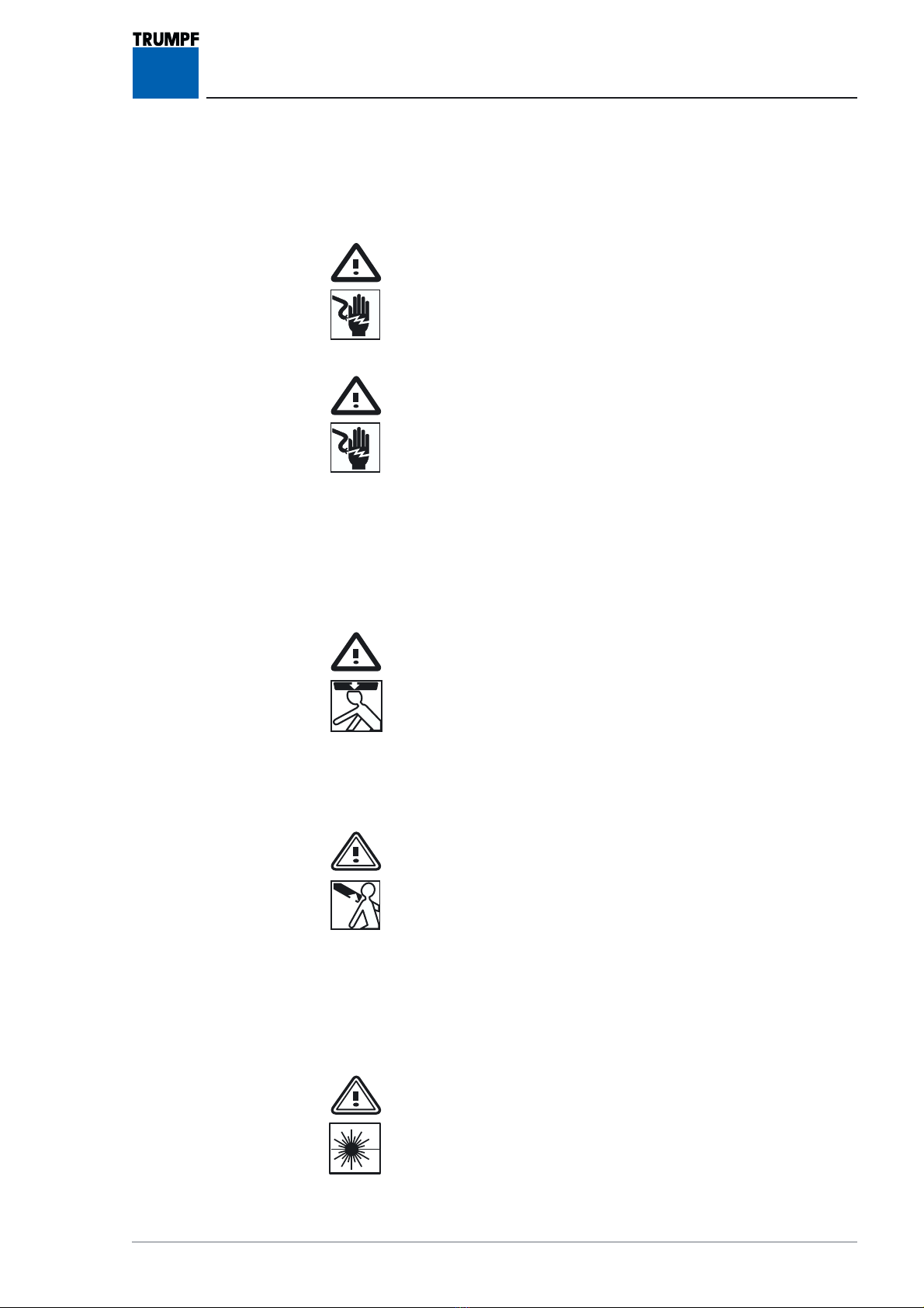
Failure to comply will certainly result in
severe or even fatal injury.
Failure to comply may result in
severe or even fatal injury.
Failure to comply may result in
minor or moderate injury or damage to property.
Offers tips on usage and handy information.
Danger of an electric shock which may result in severe or even
fatal injury.
Danger of a falling load when in the installation area under a light
system or following incorrect installation.
Danger of sudden release of the spring arm when dismantling the
lamps.
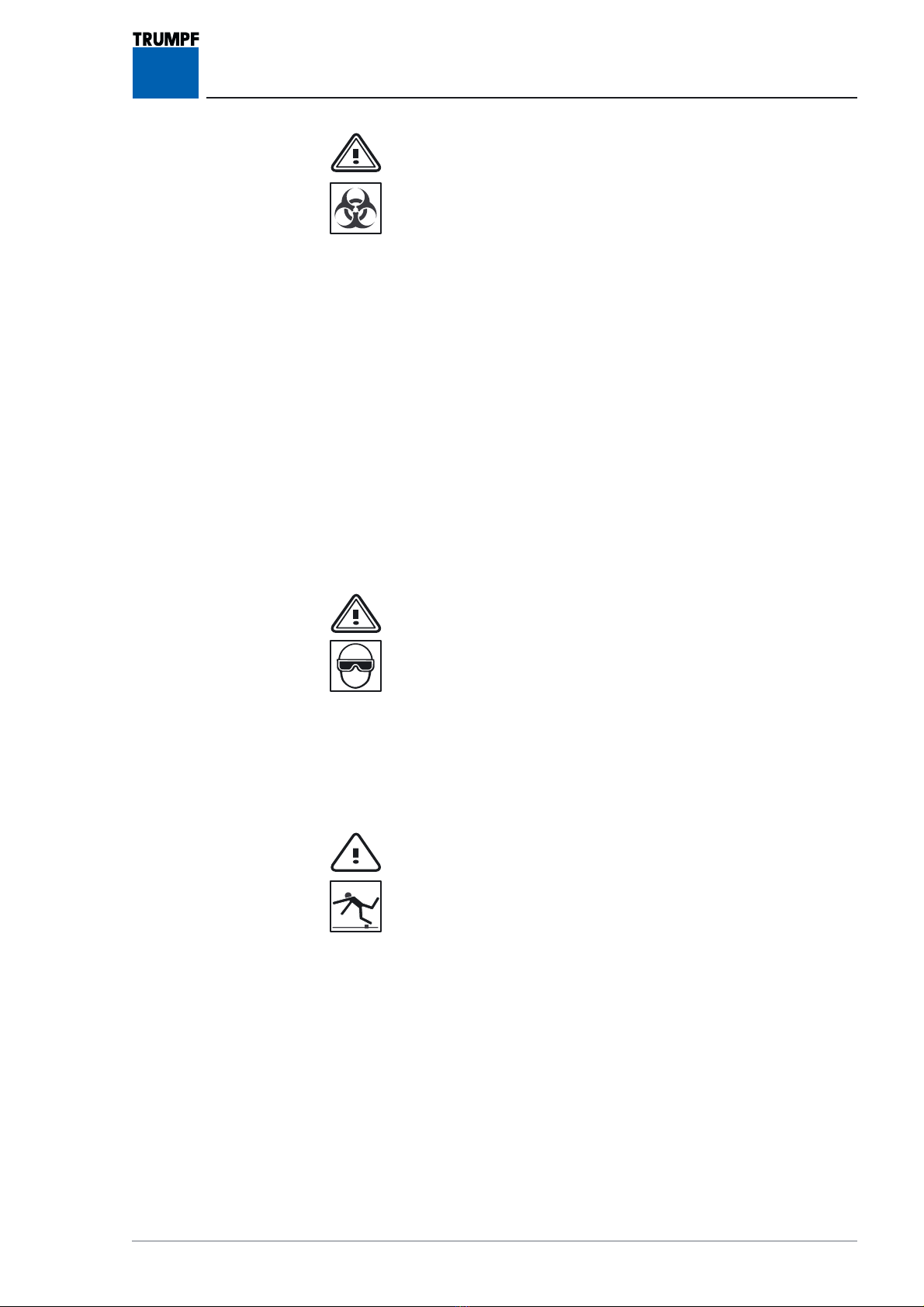
Danger of infection due to the lighting system not being cleaned
and disinfected.
Danger of eye damage due to the optional laser (Class 2) in the
central hand grip.
Danger of tripping and falling over tools or components in the
hospital staff’s path.
2.22.2
2.22.2
2.2 Symbols on the equipmentSymbols on the equipment
Symbols on the equipmentSymbols on the equipment
Symbols on the equipment
ATTENTION! Comply with operating instructions.
CE conformity marking with
number 0123 of notified body.
7200791 Service Manual for the HELION®XENION®Surgical Lighting System GB 11
2.32.3
2.32.3
2.3 Overview of the most important safety informationOverview of the most important safety information
Overview of the most important safety informationOverview of the most important safety information
Overview of the most important safety information
Hazards from electric shockHazards from electric shock
Hazards from electric shockHazards from electric shock
Hazards from electric shock
DANGER – power supply and emergency power supply:
During all servicing the building power supply and the emergency
power supply must be de-energised all-pole disconnection and
prevented from being switched back on again.
DANGER – Electric shock - High voltage 300 V:
The ballast in XENION lamps produces a starting voltage of
300 V:
When carrying out measurements in the lamps and when the power
is switched on:
• cordon off the installation site,
• avoid all contact with conductive parts.
FF
FF
Falling lighting system partsalling lighting system parts
alling lighting system partsalling lighting system parts
alling lighting system parts
DANGER – Falling lighting system parts:
During servicing it is not permitted to stand under the lighting sys-
tem.
Sudden release of spring armSudden release of spring arm
Sudden release of spring armSudden release of spring arm
Sudden release of spring arm
WARNING - Sudden release of spring arm:
• The spring arm is under high tension. If the lamp is not re-
moved in the uppermost spring arm position, the spring arm
releases suddenly, springing upwards, and can cause serious
injury.
• Only dismantle the lamp when the spring arm is in the upper-
most position.
Eye damage due to the optional laserEye damage due to the optional laser
Eye damage due to the optional laserEye damage due to the optional laser
Eye damage due to the optional laser
WARNING – Laser radiation (LASER CLASS 2) -
Do not look directly at the beam from the central hand grip:
Laser radiation does not constitute a danger to persons who are
not anaesthetised, due to the blink reflex.
Nevertheless, to avoid damaging your eyes you should not look
directly at the laser beam.
2 Your Safety is Important to Us

7200791 Service Manual for the HELION®XENION®Surgical Lighting System GB
12
2 Your Safety is Important to Us
2.32.3
2.32.3
2.3 Overview of the most important safety informationOverview of the most important safety information
Overview of the most important safety informationOverview of the most important safety information
Overview of the most important safety information
(cont(cont
(cont(cont
(cont’d)’d)
’d)’d)
’d)
FF
FF
Failure of the lamps during an operationailure of the lamps during an operation
ailure of the lamps during an operationailure of the lamps during an operation
ailure of the lamps during an operation
WARNING – Failure of the spare lamp:
Always change both lamps. When replacing the lamp always re-
place the entire lamp unit.
In the case of HELIUM models, the lamp base must also be repla-
ced.
Damage to components of the lighting systemDamage to components of the lighting system
Damage to components of the lighting systemDamage to components of the lighting system
Damage to components of the lighting system
CAUTION – Damage to lamps:
Handle and insert new lamps by the packaging film/using a soft
cloth only.
Before initial operation of the lighting systemBefore initial operation of the lighting system
Before initial operation of the lighting systemBefore initial operation of the lighting system
Before initial operation of the lighting system
WARNING – Malfunction:
Before the initial operation of the lighting system the electrical
supply has to be checked and approved by qualified staff.
7200791 Service Manual for the HELION®XENION®Surgical Lighting System GB 13
3 Observe these Work Rules
WARNING – Risk of infection:
Ask a doctor about the possible risks (e.g. hepatitis B) of
being a service technician.
After consulting a doctor, get yourself vaccinated against
hepatitis B. A booster is required every 10 years.
Disinfection of the equipment must be organised in good
time before servicing and must be carried out by the oper-
ator.
• Servicing must only be carried out on lighting systems which
have been cleaned and disinfected,
• Comply with hygiene guidelines concerning cleaning, disin-
fection and clothing,
• Only work in the operating theatre with the permission of the
user,
• Observe the code of practice in force at the medical facility,
particularly in the operating theatre,
• If you have any symptoms, consult a doctor immediately.
Inform your doctor that you have worked in hazardous areas –
even after several months.
WARNING – Wear protective eyewear:
Wear protective eyewear in case of a possible risk to eyes,
in particular when carrying out the following work:
• hammering pins or similar components in/out,
• removing tensioned springs and fuses,
• when drilling,
• when soldering,
• when using solvents, cleaning agents or other chemicals.
CAUTION – Tripping and falling:
• Put dismantled components or tools somewhere that nobody
can trip and fall over them.
• Keep your work place clean and tidy during and after servic-
ing.

7200790 Service Manual for the HELION®XENION®Surgical Lighting System GB
14
4 Table – Troubleshooting and Possible Remedies
Fault Possible causes Possible remedy Section
LED lamp indicator lit up Lamp defective Change lamp 5
Luminous field too small/
luminous intensity too low
Maladjusted limit stops Adjust luminous field 6
Noises in the light head Loose parts in the light
head/focus unit
Check light head/focus unit/ replace
filter glass assembly or defective
parts
7 ff.
HELION light head Possible causes Possible remedy Section
Inconsistent, off-centre luminous
field with HELION
M / M+/ L / L+ only
Servomotor polarity incorrect/
servomotor defective
Check polarity of
servomotor/replace focus unit
8
No light No input voltage Check building power supply 9.1
Mains fuse of building power
supply defective
Check mains fuse at automatic circuit
breaker
9.2
Electrical connections for lamp,
cardanic suspension, spring arm
or extension arm interrupted
Check internal electrical supply lines
of lamp, cardanic suspension, spring
arm or extension arm
10
Defective sliding contact in
extension arm
Replace sliding contact in extension
arm/check slip ring on central column
10.1
10.2
Defective cable in light
head/cardanic suspension
Check/replace internal electrical
supply line in light head/
replace cardanic suspension
10.3
10.4
Defective cable in spring arm Check/replace internal electrical
supply line in spring arm
10.4
10.5
Defective cable in extension arm Check/replace internal electrical
supply line in extension arm
10.6
10.7
Defective slip ring on central
column
Replace slip ring on central column 10.8
10.9
Contact areas burnt/damaged HELION M / M+ / L / L+:
Check operating voltage on focus
unit/replace unit
11.1
12.1
Line contact on PCB in light head
defective/
PCB defective/fuse on PCB
defective/cables in light head
defective
HELION M / M+ / L / L+:
Check positioning of cables on PCB
and control panel/
replace PCB/replace lamp supply
lines
11.1
12.1
Line contact on PCB in light head
defective/
PCB defective/fuse on PCB
defective/cables in light head
defective
HELION M / L:
Check positioning of cables on PCB
and control panel/
replace PCB/replace cables in light
head
11.2

157200790 Service Manual for the HELION®XENION®Surgical Lighting System GB
4 Table – Troubleshooting and Possible Remedies
Fault Possible cause Possible remedy Section
No light Line contact on PCB in light head
defective/
PCB defective/
fuse on PCB defective
Check positioning of cables on PCB
and control panel/
replace PCB/replace fuse/
replace cables in light head
12.2
Line contact on PCB in light head
defective/
PCB defective/
fuse on PCB defective
Check positioning of cables on PCB
and control panel/
replace PCB/replace fuse
13.1
No dimmer function Line contact on PCB/control
panel in light head defective
Check positioning of cables on PCB
and control panel
13.2
7200790 Service Manual for the HELION®XENION®Surgical Lighting System GB
16
4 Table – Troubleshooting and Possible Remedies
XENION light head
No light No input voltage Check building power supply 9.1
Mains fuse for building power
supply defective
Check mains fuse at automatic circuit
breaker
9.2
Electrical connection for lamp,
cardanic suspension, spring arm
or extension arm interrupted
Check internal electrical supply lines
for lamp, cardanic suspension, spring
arm or extension arm
10
Defective sliding contact in
extension arm
Replace sliding contact in extension
arm/check slip ring on central column
10.1
10.2
Defective cable in light
head/cardanic suspension
Check/replace internal electrical
supply line in light head/
replace cardanic suspension
10.3
10.4
Defective cable in spring arm Check/replace internal electrical
supply line in spring arm
10.4
10.5
Defective cable in extension arm Check/replace internal electrical
supply line in extension arm
10.6
10.7
Defective slip ring on central
column
Replace slip ring on central column 10.8
10.9
Contact areas burnt/damaged Check operating voltage at focus
unit/replace unit
13.1
Line contact on PCB in light head
defective/
PCB defective/fuse on PCB
defective/cables in light head
defective/ballast defective
Check positioning of cables on PCB
and control panel/replace PCB/
replace fuse on PCB/
replace cables in light head
The halogen lamp does not light
up when switched on
Halogen lamp defective/no
power supply available
XENION L / L+ only:
Replace lamp/check voltage of
electronics
13.1
5.4
Only the halogen lamp lights up Metal vapour lamp
defective/power supply to
electronics too low/high
XENION L / L+ only:
Replace lamp/check LED indicator on
the electronics/check voltage
No dimmer function Line contact on
PCB/potentiometer/ballast in
light head defective
Check positioning of cables on
PCB/potentiometer/control
panel/replace potentiometer
13.2
Dimmer functioning incorrectly Reversed potentiometer polarity Change potentiometer polarity

177200790 Service Manual for the HELION®XENION®Surgical Lighting System GB
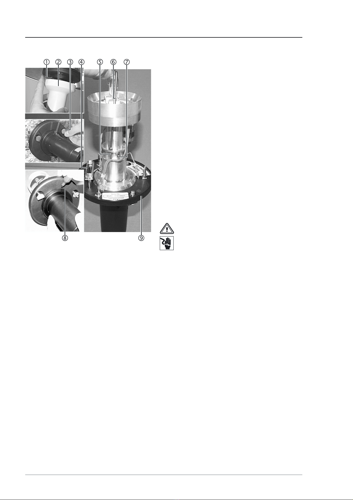
Figure 01
Figure 02
5 Changing the Lamp
5.15.1
5.15.1
5.1 Changing the lamp of the HELION SChanging the lamp of the HELION S
Changing the lamp of the HELION SChanging the lamp of the HELION S
Changing the lamp of the HELION S
The lamp does not light up.
Removal:
1. Carefully turn the lamp holder 2and remove it
from the HELION S lamp 3.
2. Carefully remove the old lamp 1from the lamp
holder 2and dispose of it in the appropriate
manner.
Installation:
3. Fit the new lamp 1holding it by the packaging
film/using a soft cloth and fit the components as
described above, but in the reverse order.
5.25.2
5.25.2
5.2 Changing the lamp of the HELION M/Changing the lamp of the HELION M/
Changing the lamp of the HELION M/Changing the lamp of the HELION M/
Changing the lamp of the HELION M/
M+ / L/L+M+ / L/L+
M+ / L/L+M+ / L/L+
M+ / L/L+
The display 8is lit up. The lamp is defective.
Removal:
1. Unlock the central hand grip 2by means of the
unlocking device 1and remove it.
WARNING – Failure of the spare lamp:
• Always change both lamps.
• When replacing the lamp always replace the
lamp base too.
2. Undo the three screws 3and remove the focus
unit 4.
3. Unscrew the two cross-recessed head screws 5
and remove the old lamp 6together with the
base 7 by pulling it upwards and dispose of it in
an appropriate manner.
Installation:
4. Fit the new lamp 6together with the base 7
holding it by the packaging film/using a soft cloth
and fit the components as described above, but
in the reverse order.
5. Insert the focus unit 4into the lamp so that both
the plug connectors 9are aligned.
6. Tighten the three screws 3by hand.
7. Attach the central hand grip 2.

18 7200790 Service Manual for the HELION®XENION®Surgical Lighting System GB
5 Changing the Lamp
Figure 03 5.35.3
5.35.3
5.3 Changing the lamp of the XENION M/Changing the lamp of the XENION M/
Changing the lamp of the XENION M/Changing the lamp of the XENION M/
Changing the lamp of the XENION M/
M+M+
M+M+
M+
Removal:
1. Unlock the central hand grip 2by means of the
unlocking device 1and remove it.
2. Undo the three screws 3and remove the focus
unit 5.
3. Remove the old metal vapour lamp 4by pulling
it upwards and dispose of it in an appropriate man-
ner.
Installation:
4. Fit the new metal vapour lamp 4holding it by
the packaging film/using a soft cloth and assemble
the components as described above, but in the
reverse order.
5. Insert the focus unit 5into the lamp so that both
the plug connectors 6are aligned.
6. Tighten the three screws 3by hand.
7. Attach the central hand grip 2.
197200790 Service Manual for the HELION®XENION®Surgical Lighting System GB
5 Changing the Lamp
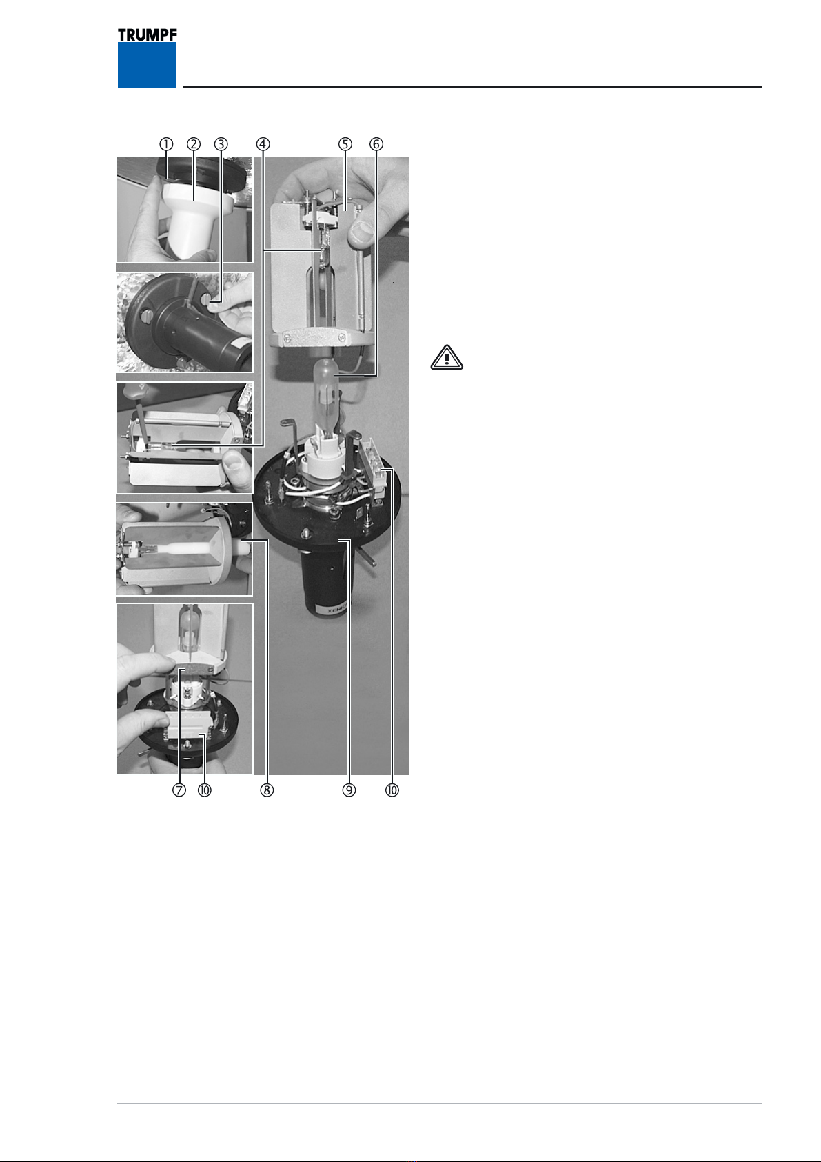
5.45.4
5.45.4
5.4 Changing the lamp of the XENION L/Changing the lamp of the XENION L/
Changing the lamp of the XENION L/Changing the lamp of the XENION L/
Changing the lamp of the XENION L/
L+L+
L+L+
L+
Removal:
1. Unlock the central hand grip 2by means of the
unlocking device 1and remove it.
2. Undo the three screws 3and remove the focus
unit 9.
3. Turn the aperture attachment 545 degrees to
the left (anti-clockwise) and remove by pulling up-
wards.
WARNING – Failure of the spare lamp:
• Always change both lamps (supplied as a
set).
4. Using a screwdriver, push out the old halogen lamp
4, remove it from the aperture attachment 5
and dispose of it in an appropriate manner.
5. Remove the old metal vapour lamp 6by pulling
it upwards and dispose of it in an appropriate man-
ner.
Installation:
6. Insert the halogen lamp 4together with the ac-
companying plastic mount 8into the aperture
attachment 5.
7. Insert new metal vapour lamp 6holding it by the
packaging film/using a soft cloth.
8. Insert the aperture attachment 5so that the sur-
face 7and the connector Aare aligned.
9. Assemble the components as described above, but
in the reverse order.
10.Insert the focus unit 9so that both the plug con-
nectors Aare aligned.
11.Attach the central hand grip 2.
Figure 04
20 7200790 Service Manual for the HELION®XENION®Surgical Lighting System GB
6 Setting the Luminous Field
Figure 01 6.16.1
6.16.1
6.1 Setting the luminous field for the HELI-Setting the luminous field for the HELI-
Setting the luminous field for the HELI-Setting the luminous field for the HELI-
Setting the luminous field for the HELI-
ON M/M+ / L/L+ON M/M+ / L/L+
ON M/M+ / L/L+ON M/M+ / L/L+
ON M/M+ / L/L+
Setting is described using the HELION L as an ex-
ample.
Removal:
1. Unlock the central hand grip 2by means of the
unlocking device 1and remove it.
2. Undo the three screws 3and remove the focus
unit 9.
3. Using an Allen key size 25 6:
- unscrew the long cheese head screw 5a short
way,
- screw the short cheese head screw 7in a short
way.
Installation:
4. Fit the components as described above, but in the
reverse order.
WARNING – Electric Shock:
The following adjustments must be made
with the power supply switched on.
Cordon off installation site and proceed
with great care.
5. Switch on the power supply and the lamp.
6. Mark the maximum and minimum luminous field
diameters on the hand grip according to the lamp
specification 8.
Removal:
7. Switch on the power supply and the lamp.
8. Undo the three screws 3and remove the focus
unit 9.
9. With an Allen key size 2.5 6adjust the long chee-
se head screw 5and the short cheese head screw
7according to the markings.
Installation:
10.Fit the components as described above, but in
reverse order.
Functional test:
11. Carry out functional test.
12. Repeat procedure if necessary.
13. Fix the long cheese head screw 5and the short
cheese head screw 7with screw-locking varnish.
This manual suits for next models
4
Table of contents
Other Trumpf Medical Equipment manuals


Popular Medical Equipment manuals by other brands


Getinge
Getinge Arjohuntleigh Nimbus 3 Professional Instructions for use

Mettler Electronics
Mettler Electronics Sonicator 730 Maintenance manual

Pressalit Care
Pressalit Care R1100 Mounting instruction

Denas MS
Denas MS DENAS-T operating manual

bort medical
bort medical ActiveColor quick guide

AccuVein
AccuVein AV400 user manual


