Trumpf TruLight 1000 User manual
Installation manual
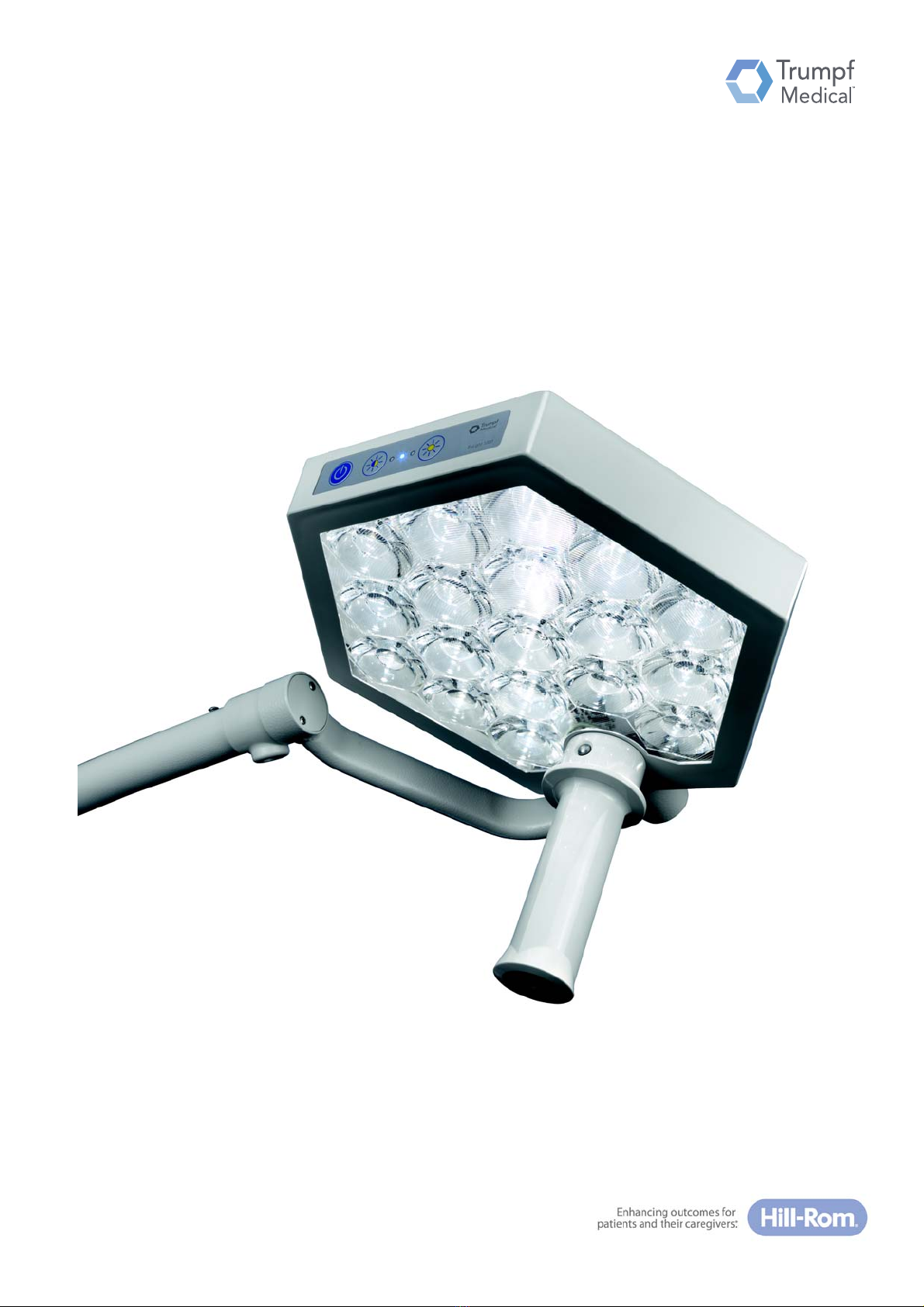
TruLight™ 1000 examination light
English
en-GB

This page is left intentionally blank.

55000-00019_002_01 – 1695231 – 17/10/2018 3
Instructions for service personnel
Please read this installation manual very carefully and take into account the
safety instructions and the special requirements for installation.
This installation manual apply to:
Device versions TruLight™ 1000 lighting system:
• Version with light head as ceiling-mounted version.
• Version with light head as wall-mounted version.
• Version with light head as mobile pedestal version.
• Version with a light head on TRUMPF Medizin Systeme GmbH + Co. KG
ceiling-mounted supply unit.

55000-00019_002_01 – 1695231 – 17/10/2018 4
How to contact us
Manufacturer and distributor TRUMPF Medizin Systeme GmbH + Co. KG
Carl-Zeiss-Straße 7–9
07318 Saalfeld
Germany
Telephone: +49 3671 586-0
Fax: +49 3671 586-41165
info@trumpfmedical.com
www.trumpfmedical.com
Trumpf Medical will hereinafter be used as a synonym for TRUMPF Medizin Systeme
GmbH + Co. KG to improve readability.
Technical Customer Service Telephone: +49 (0)3671 586-41911
Fax: +49 (0)3671 586-41175
E-mail service.wwo@trumpfmedical.com
The contact details for the current sites of the technical customer service in the indi-
vidual countries are provided on the Internet at www.trumpfmedical.com.
In the following, Technical Customer Service will be used as a synonym for Trumpf
Medical Customer Service and for technicians of service operators authorised and
trained by Trumpf Medical.
55000-00019_002_01 – 1695231 – 17/10/2018 5
Validity
Other applicable documents
Designation Document number Material No.
Service Manual
TruLight 1000 DE
55000-00022 1867293
Spare Parts List
TruLight 1000 DE / EN
55000-00039 1857652
Instruction Manual
TruLight 1000 DE
55000-00012 1695232

55000-00019_002_01 – 1695231 – 17/10/2018 6
Notes relating to this documentation
Copyright and property rights
Copyright • All rights reserved. This installation manual is protected by copyright.
• Any use not currently regulated by law must be approved in writing by TRUMPF
Medizin Systeme GmbH + Co. KG, hereinafter referred to as Trumpf Medical.
• Trumpf Medical will assume no liability whatsoever arising from or connected
with the use of unapproved information by any person or company.
Modifications and translations
Modifications to the device • We constantly work on the further development of our products and reserve the
right to make changes to the scope of delivery in terms of form, equipment and
technology.
Changes to the installation manual • The content of the installation manual can be changed at any time without prior
notice.
• Please keep up to date on the current version of the instructions, e.g. using the
Trumpf Medical Online Information System (OIS) at regular intervals.
Translations • The German-language version of this Installation Manual shall be binding as
regards translations into foreign languages.
Trademarks
•TruLight
™ 1000 is a registered trademark of TRUMPF GmbH + Co. KG.
• All other brands listed in the installation manual are the exclusive property of the
respective manufacturer.

7
55000-00019_002_01 – 1695231 – 17/10/2018
Table of Content
1Important information for safe installation ....................................................................... 10
1.1 Details for identification of the device............................................................................................................ 10
1.2 Details for identification of the installation manual ....................................................................................... 10
1.3 Delivery ........................................................................................................................................................... 10
1.3.1 Transportation damage ......................................................................................................................................................10
1.3.2 Identifying the components based on serial numbers .......................................................................................................11
1.4 Required installation equipment .................................................................................................................... 11
1.5 Qualification of service staff ........................................................................................................................... 11
1.6 Ambient conditions for operation and storage .............................................................................................. 11
1.6.1 Ambient conditions for operation ......................................................................................................................................11
1.6.2 Ambient conditions for storage ..........................................................................................................................................11
1.7 Conformity ...................................................................................................................................................... 12
1.7.1 Identification.......................................................................................................................................................................12
1.7.2 Proper use...........................................................................................................................................................................12
1.7.3 Special features...................................................................................................................................................................12
1.7.4 Improper use.......................................................................................................................................................................12
1.8 Exclusion of liability......................................................................................................................................... 13
1.9 Documentation of the installation.................................................................................................................. 13
1.10 Disposal........................................................................................................................................................... 13
2On-site requirements ....................................................................................................... 14
2.1 Approval of wall and ceiling anchorage .......................................................................................................... 14
2.2 Fasteners and mounting methods .................................................................................................................. 14
2.3 On-site electrical installation .......................................................................................................................... 15
3Safety instructions ........................................................................................................... 16
3.1 Structure of the safety instructions in this installation manual...................................................................... 16
3.1.1 Indicating risk of injury .......................................................................................................................................................16
3.1.2 Indicating damage to property ...........................................................................................................................................16
3.1.3 Indicating additional information .......................................................................................................................................16
3.2 Additional symbols for safety instructions...................................................................................................... 16
3.3 Symbols on the device .................................................................................................................................... 16
3.4 Overview of the most important safety instructions...................................................................................... 17
4Identification of the lighting system.................................................................................. 20
4.1 Use of serial numbers and device labels......................................................................................................... 20
4.1.1 Markings on the ceiling-mounted version ..........................................................................................................................20
4.1.2 Markings on the wall-mounted version..............................................................................................................................20
4.1.3 Markings on the mobile stand version ...............................................................................................................................21
5Installation of ceiling version ............................................................................................ 22
5.1 Overview of assemblies for central axis.......................................................................................................... 22
5.1.1 Central axis assembly..........................................................................................................................................................22
5.1.2 Support arm system assembly............................................................................................................................................24
5.1.3 Light unit assembly .............................................................................................................................................................24
5.2 Power supply to the ceiling version ................................................................................................................ 24
5.3 Attachment of ceiling anchor plate to the slab ceiling ................................................................................... 25
5.3.1 Attachment of ceiling anchor plate with heavy-duty anchors............................................................................................25
5.4 Installation of ceiling pipe flange plate on the ceiling anchor plate ............................................................... 26
5.4.1 Installation with threaded rods ..........................................................................................................................................26
5.4.2 Assembly with hexagonal profiles ......................................................................................................................................27
5.5 Installation of ceiling pipe flange plate on the slab ceiling ............................................................................. 28
5.5.1 Attachment of ceiling pipe flange plate with heavy-duty anchors .....................................................................................28

Table of Content
8
55000-00019_002_01 – 1695231 – 17/10/2018
5.6 Connecting the on-site power supply ............................................................................................................. 29
5.6.1 Input voltage 100 V - 240 V.................................................................................................................................................29
5.7 Mount canopy................................................................................................................................................. 29
5.8 Installation of the support arm system on the central axis ............................................................................ 30
5.8.1 Preparing for the assembly.................................................................................................................................................30
5.8.2 Dismantling the circlip ........................................................................................................................................................30
5.8.3 Mounting the circlip............................................................................................................................................................32
5.8.4 Checking the secure fit of the circlip...................................................................................................................................33
5.8.5 Completing the installation.................................................................................................................................................34
5.9 Installation of the light unit on the support arm system ................................................................................ 35
5.10 Controlling driving movements....................................................................................................................... 36
5.10.1 Check levelling of the lighting system.................................................................................................................................36
5.10.2 Rotation / swivel ranges of the support arm system..........................................................................................................36
5.10.3 Rotation / swivel ranges of the light head..........................................................................................................................36
6Installation of wall version ............................................................................................... 37
6.1 Overview of assemblies of wall bearing.......................................................................................................... 37
6.1.1 Wall bearing assembly........................................................................................................................................................37
6.1.2 Support arm system assembly............................................................................................................................................37
6.1.3 Light unit assembly .............................................................................................................................................................37
6.2 Power supply to the wall version.................................................................................................................... 38
6.3 Fastening the wall bearing .............................................................................................................................. 39
6.4 Connecting the on-site power supply ............................................................................................................. 41
6.4.1 Input voltage 100 V - 240 V.................................................................................................................................................41
6.5 Installation of the support arm system on the wall bearing........................................................................... 43
6.5.1 Preparing for the assembly.................................................................................................................................................43
6.5.2 Dismantling the circlip ........................................................................................................................................................43
6.5.3 Mounting the circlip............................................................................................................................................................45
6.5.4 Checking the secure fit of the circlip...................................................................................................................................46
6.5.5 Completing the installation.................................................................................................................................................47
6.6 Installation of the light unit on the support arm system ................................................................................ 48
6.7 Controlling the driving movements ................................................................................................................ 49
6.7.1 Check levelling of the lighting system.................................................................................................................................49
6.7.2 Rotation / swivel ranges of the support arm system..........................................................................................................49
6.7.3 Rotation / swivel ranges of the light head..........................................................................................................................49
7Assembly of mobile stand version ..................................................................................... 50
7.1 Overview of assemblies .................................................................................................................................. 50
7.1.1 Stand base assembly...........................................................................................................................................................50
7.1.2 Stand pipe assembly ...........................................................................................................................................................50
7.1.3 Spring arm assembly...........................................................................................................................................................50
7.1.4 Light unit assembly .............................................................................................................................................................50
7.2 Power supply of the stand version.................................................................................................................. 51
7.3 Assembling the stand base ............................................................................................................................. 52
7.4 Assembling the stand rod ............................................................................................................................... 53
7.5 Assembly of the spring arm on the stand rod................................................................................................. 54
7.5.1 Preparing for the assembly.................................................................................................................................................54
7.5.2 Dismantling the circlip ........................................................................................................................................................54
7.5.3 Mounting the circlip............................................................................................................................................................56
7.5.4 Checking the secure fit of the circlip...................................................................................................................................57
7.5.5 Completing the installation.................................................................................................................................................57
7.6 Connecting the internal power supply............................................................................................................ 58
7.7 Installation of the light unit on the spring arm ............................................................................................... 59

Table of Content
9
55000-00019_002_01 – 1695231 – 17/10/2018
7.8 Controlling the driving movements ................................................................................................................ 60
7.8.1 Rotation / swivel ranges of the spring arm.........................................................................................................................60
7.8.2 Rotation / swivel ranges of the light head..........................................................................................................................60
8Functional testing and instruction..................................................................................... 61
8.1 Functional test of the lighting system............................................................................................................. 61
8.2 Handover of the lighting system ..................................................................................................................... 62
9Adjustments ....................................................................................................................63
9.1 Adjusting the spring force on the spring arm ................................................................................................. 63
9.2 Adjusting the brake force of the quarter bracket ........................................................................................... 64
9.3 Replacing the internal equipment fuse of the mobile stand version..............................................................65
10 Consumables ................................................................................................................... 66
11 Technical data.................................................................................................................. 67
11.1 Device data ..................................................................................................................................................... 67
11.2 EMC information............................................................................................................................................. 68
12 Attachment .....................................................................................................................73
12.1 Contents of attachment .................................................................................................................................. 73
12.1.1 Circuit plan for ceiling version 100 V - 240 V / #1699488...................................................................................................74
12.1.2 Circuit diagram for mobile version 100 V - 240 V cable connection / #1699646 ...............................................................76
12.1.3 Circuit diagram for wall version 100 V - 240 V fixed connection / #1699647.....................................................................78
12.1.4 Drawing of switch cabinet TL 1000, 230V / #1698267 .......................................................................................................79
12.1.5 Borehole template for ceiling anchor plate, ceiling pipe flange plate / #1690273 ............................................................80
12.1.6 Borehole template for wall bearing / #4058120 ................................................................................................................81
55000-00019_002_01 – 1695231 – 17/10/2018 10
1 Important information for safe installation
1.1 Details for identification of the device
This installation manual is intended solely for devices that are shown on the device
label with the following information:
Device identification
1.2 Details for identification of the installation manual
Up-to-dateness of this installation manual To indicate the updated status of the installation manual, all pages are marked with a
7-figure identification number and the status:
Marking of the installation manual – Material no.: 1695231
– Date of publication: 17/10/2018
– Document number: 55000-00019_002_01
This marking is binding for the validity of the installation manual and must not be
removed irrespective of the type of publication (in printed or electronic form, in full
or excerpted).
1.3 Delivery
Before installation, check the delivery for completeness and for any possible
transportation damage. Unpack to check the delivery of all components. The
components can be identified by means of the order number of the delivery note and
the order-specific dimension sheet. Always store the delivery note with the main
components (light head or support arm system).
1.3.1 Transportation damage
Damage claims Claims for damage cannot be accepted unless Trumpf Medical is notified without
delay. In the event of damage during transport or missing components, please send
Trumpf Medical a report containing the following information:
Accompanying documents • Damage report giving details of damage or defects using the: Service Advice
Form (F60.M028)
• Main serial number of the lighting system or the serial numbers of the damaged
components
• Order number (shown on the delivery note and / or the order-specific dimension
sheet)
• Name and address of the customer
•Consignee
Address for returns In the event of a return, use the original packaging if possible.
Address returns to:
TRUMPF Medizin Systeme GmbH + Co. KG
Carl-Zeiss-Straße 7–9
07318 Saalfeld
Germany
Descriptor/rating Type Material no.
TruLight™ 1000 TruLight™ 1000 pre-assembly set 4058051
TruLight™ 1000 TruLight™ 1000 ceiling 4058110
TruLight™ 1000 TruLight™ 1000 wall 4058120
TruLight™ 1000 TruLight™ 1000 mobile 4058130
TruLight™ 1000 TruLight™ 1000 pendant 4058140

11
1 Important information for safe installation
55000-00019_002_01 – 1695231 – 17/10/2018
1.3.2 Identifying the components based on serial numbers
Serial numbers The components of the lighting system are marked by serial numbers:
• The serial numbers specify the components of a specific lighting system uniquely
in such a way that they cannot be confused.
• The components of a lighting system are listed in the delivery note of the
packaging by serial number.
• An overview of the serial number marking points on the device can be found in
Chapter 4.1, P. 20.
1.4 Required installation equipment
The following equipment is required to install the lighting system:
• Two ladders of the required length
• Standard drilling equipment
or
• HILTI DD-EC 1 core drill
– with the corresponding drill bit
• Drilling templates
– Ceiling mount: (#1704432)
– Wall attachment: (#4058120)
•Level
• Torque spanner
• Calibrated lux meter
•Multimeter
• Standard toolkit
Tool List The tool list (TMS900we, 2009-12-21) contains a list of all the available special tools
with material numbers and can be downloaded from the Trumpf Medical Online
Information System (OIS).
1.5 Qualification of service staff
Professional qualifications The device may only be installed, maintained and repaired by the Trumpf Medical
Customer Service unit or by authorised Trumpf Medical Service partners.
1.6 Ambient conditions for operation and storage
Various ambient conditions apply to the operation and temporary storage of the
device.
1.6.1 Ambient conditions for operation
• Ambient temperature: 10 °C to 40 °C
• Relative humidity: 30% to 75%
• Air pressure: 700 hPa to 1060 hPa
• Operating height: max. 3000 m above sea level
1.6.2 Ambient conditions for storage
• Ambient temperature: -15 °C to +60 +°C
• Relative humidity: 5% to 95%
• Air pressure: 500 hPa to 1060 hPa
12
1 Important information for safe installation
55000-00019_002_01 – 1695231 – 17/10/2018
1.7 Conformity
1.7.1 Identification
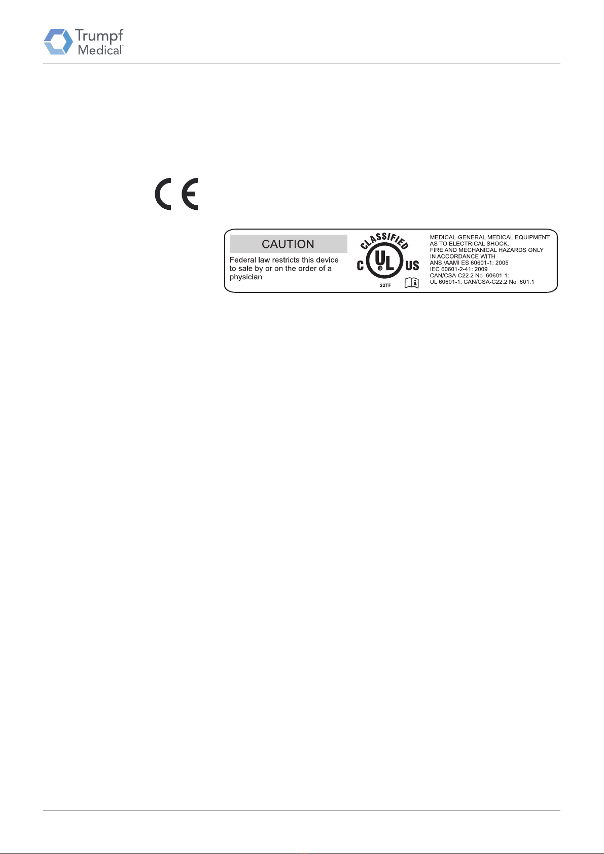
Conformity The manufacturer declares that this product conforms to the fundamental
requirements according to MDD Appendix I and documents the same by means of
the CE and UL marking.
CE mark: This device is a Class I medical device as defined by the European Medical
Device Directive (MDD).
UL mark UL mark: device tested by Underwriter Laboratories Inc. for the USA and Canada with
regard to shock and fire hazard and also mechanical endangerment.
1.7.2 Proper use
Proper use Lighting unit for the local illumination of the patient’s body to support diagnoses or
treatments which may be interrupted in case of light failure without hazard to the
patient.
Working range • The working range lies at a distance between 70 and 150 cm to the area being
examined.
• The device is suitable for continuous operation.
• Each use beyond the aforementioned conditions is considered to fall outside the
scope of proper use. Only the user or operator will be liable for any loss or
damage arising as a result.
1.7.3 Special features
High light intensity To ensure good visibility, the light head has a high light intensity.
Overlap of the light fields • Visible light also generates heat in the examination area due to physical effects.
The light intensity must be reduced when perfusion is reduced or the tissue starts
to dry out.
Examinations in the field of vision • For examinations in the facial area with unprotected and open eyes, high levels of
local light intensities may lead to damage to eyesight. The patient's eyes must be
closed or protected as necessary (e.g. with safety goggles with an optical density
of at least 2 or designed according to protection level 6 EN169).
1.7.4 Improper use
Improper use The examination light is not intended for use in operating theatres.
• Additional load on the light support is not permitted.
• The device may not be exposed to severe vibration.
Restriction • The device is not suitable for operation in areas at risk of explosions
• The device is not suitable for use in rooms or areas in which inflammable
mixtures of anaesthetics with air or oxygen or laughing gas (N20) are used.
• The device should not be used in the vicinity of strong magnetic fields.
• Mixtures of combustible anaesthetic vapours with oxygen or laughing gas may
arise in the vicinity of the device in such a high concentration that ignition could
occur under certain circumstances. The danger area is formed in accordance with
EN 11197 in an area between 5 cm and 25 cm from the point of outflow or escape
of the gas.
/ AMD1: 2012;
/ AMD1: 2013;
2014;
13
1 Important information for safe installation
55000-00019_002_01 – 1695231 – 17/10/2018
1.8 Exclusion of liability
Exclusion of liability The Trumpf Medical warranty for the product requires that:
• the device is used exclusively for the proper use and is operated and maintained
in accordance with the provisions of this installation manual
• only original spare parts or accessories approved by Trumpf Medical are used
• no modifications are made to the device
• inspections and maintenance work are carried out at the time intervals specified
• an initial commissioning is carried out and the device is released for operation
with a handover declaration
1.9 Documentation of the installation
Installation must be performed with the use of an installation report (TK_IS_200).
Download the specified report in electronic format via the online information system,
complete it and hand it over to the Technical Customer Services unit of TRUMPF
Medizin Systeme GmbH & Co. KG.
The installation reports contain all the important test and installation steps and the
documentation required for handover of the device.
The following must be observed when documenting the installation reports:
• Documentation about the serial number of the installed components, stating the
assembly site.
The serialisation structure prescribed during delivery must be adhered to during
installation. If serial equipment other than that prescribed by the manufacturer
is to be installed, this must be noted on the various installation reports.
• The handover of the lighting system for operation must be confirmed by the
operator.
The lighting system must be handed over to the operator following
commissioning and testing by the service staff of the installer. The operator must
be instructed in the functional check and visual inspection, the adjustment work
and in cleaning and caring for the lighting system in accordance with the valid
installation manual.
1.10 Disposal
The device must be disposed of in accordance with the requirements of directive
WEEE II 2012 / 19 / EU and relevant national regulations at a suitable waste disposal
point for the recycling of electrical and electronic devices.
RoHS conformity • The device meets the requirements of Directive 2011/65/EU RoHS (restriction of
the use of certain hazardous substances in electrical and electronic devices).
55000-00019_002_01 – 1695231 – 17/10/2018 14
2 On-site requirements
Care must be taken to ensure that the ceiling and wall anchorage of the lighting
system takes into account all the circumstances that apply to each individual case,
that the approval of the relevant building authorities has been obtained and that all
installation work is carried out in accordance with the regulations and using suitable
tools.
2.1 Approval of wall and ceiling anchorage
Declaration of acceptance by the structural
engineer
The condition and sustainability of the mounting structure must be inspected by a
structural engineer and confirmed in a certificate. This verification of the structural
calculation for the load-bearing capacity must be done prior to installation and must
be available.
Aborted holes If drilling of a hole has been aborted, for example, by drilling into the reinforcement,
the structural engineer in charge must be involved since adequate structural load
distribution may be endangered.
Observe and follow construction
provisions
The respectively valid national and regional construction provisions must be
complied with.
2.2 Fasteners and mounting methods
Fasteners are not part of the scope of delivery. The selection of fasteners is the
responsibility of the structural examination and approval of the responsible building
authority.
Ceiling anchoring
Reinforced concrete ceiling, class C20/25 The following fasteners are recommended for well-constructed reinforced concrete
ceilings of class C20/25 (or better quality):
• Four ceiling anchors of the type: HILTI
• Approval document: ETA-98/0001 (European Technical Approval)
• Type: HST M10x90
Strength of the slab ceiling The minimum component thickness of the slab ceiling to use ceiling anchors must be
120 mm. In case of lower slab ceiling thicknesses, different fasteners are usually
proposed in the order-specific dimension sheet.
Manufacturer processing regulations The processing regulations of the fastener manufacturers must be taken into
account. The ceiling anchor plate / wall pipe flange plate must lie flush on the fixing
substrate for correct load distribution.
Observe and follow construction
provisions
The respectively valid national and regional construction provisions must be
complied with.
Load data for ceiling anchorage:
Reinforced concrete wall, class C20/25 The following fasteners are recommended for well-constructed reinforced concrete
walls of class C20/25 (or better quality):
• Two heavy-duty anchors of the type: HILTI
• Approval certificate no. ETA-98/0001
• Type: HST M10x90
Lightweight construction walls In case of lightweight construction walls that cannot be subjected to loads, it is
necessary to insert a metal construction. The suitability of the metal construction
provided by the customer must be confirmed in writing and documented by the
customer (operator or representative commissioned and authorised by the operator,
e.g. planners, architects, etc.).
Weight force Bending moment
350 N 70 Nm
15
2 On-site requirements
55000-00019_002_01 – 1695231 – 17/10/2018
Load data for wall anchorage:
2.3 On-site electrical installation
The on-site electrical connections must be made in accordance with the TruLight™
1000 planning rules by a specialised company appointed by the customer. The
following requirements must be complied with:
Execution by a specialised electrical
company
• Planning, execution and testing of the electrical installation must be performed
on-site by professional and specialised electrical designers and state-licensed
electrical specialised companies.
Country-specific regulations • If it is required by the regulations applicable in the respective country that the
device be connected to the power supply by authorised electricians, then this
subsequent procedure must be carried out.
All-pin disconnecting device for the power
supply
• It must be possible to disconnect all pins of the power supply lines from the
mains power supply by a device provided on-site.
• The series terminals must be freely accessible for installation of the device and
for carrying out the prescribed electrical safety tests.
• The electrical installations for the room in question must meet the requirements
of the nationally applicable regulations.
• For the Federal Republic of Germany, DIN VDE 0100 Part 710 applies.
• For the USA, the requirements of NFPA 70 and NFPA 99 apply
Electrical fuses for ME devices
For ME devices with permanent connections, the device used for
electrical insulation of the circuits must have a lock that can be set to the
off position to disconnect the circuits from the mains supply. A mains
supply switch, when used as an electrical insulation device, must meet
the requirements of IEC 61058-1.
If ME devices are not permanently installed and do not have a mains
switch, a suitable plug device for disconnecting the ME device from the
mains will meet the requirements.
Weight force Bending moment
70 N 70 Nm
NOTE
55000-00019_002_01 – 1695231 – 17/10/2018 16
3 Safety instructions
3.1 Structure of the safety instructions in this installation
manual
In this installation manual, important information is marked by graphic symbols or
signal words.
3.1.1 Indicating risk of injury
Signal words such as DANGER, WARNING or CAUTION indicate the severity of the
hazard. Various triangle symbols are used to add visual emphasis.
DANGER indicates an immediately dangerous situation in which non-compliance can
cause death or serious injury.
WARNING indicates a potentially dangerous situation in which non-compliance may
cause death or serious injuries.
+CAUTION indicates a potentially dangerous situation in which non-compliance may
cause minor injuries.
3.1.2 Indicating damage to property
ATTENTION indicates a potentially dangerous situation, which, –unless avoided,– can
lead to damage to property.
3.1.3 Indicating additional information
NOTE provides you with additional information and helpful tips for safe and efficient
use of the device.
3.2 Additional symbols for safety instructions
Gas explosion: warns of explosive ignition of gas mixtures
Electric shock: indicates an electric shock hazard which could cause serious injury or
even death
The spring arm may bounce up: warns of the spring arm jumping up while
dismantling the light head / flat screen
Lighting system falling down: warns of a sudden downwards movement of the light
system when it is exposed to additional loads
Damage to surfaces: warns against damage to surfaces caused by unsuitable
cleaning agents and disinfectants
3.3 Symbols on the device
CE conformity mark: certifies the conformity of the device with the European
product directive (Medical Device Directive (MDD).
DANGER
WARNING
CAUTION
ATTENTION
NOTE
17
3 Safety instructions
55000-00019_002_01 – 1695231 – 17/10/2018
Follow the Instruction Manual: refers to the instruction manual
UL mark: device has been tested by Underwriter Laboratories Inc. for the USA and
Canada. UL / cUL classification regarding electric shock, fire hazard and mechanical
hazard only in accordance with ANSI / AMI ES60601-1: 2005/AMD1: 2012,
IEC 60601-2-41:2009/AMD1:2013, CAN/CSA-C22.2 No. 60601-1: 2014, UL 60601-1,
CAN/CSA-C22.2 No. 601.1.
3.4 Overview of the most important safety instructions
Requirements for the installation site
Gas explosion
The lighting system is not suitable for use in an environment
in which flammable mixtures of anaesthetics with oxygen or
laughing gas in a high concentration are used. Mixtures of combustible
anaesthetic vapours with oxygen or laughing gas may arise in the vicinity
of the device in a sufficiently high concentration that ignition may occur
under certain circumstances.
The danger area is formed in accordance with EN 11197 in an area
between 5 cm and 25 cm from the point of outflow or escape of the gas.
Strong magnetic fields
The support arm systems of the lighting systems must not be used in the
vicinity of strong magnetic fields.
BF / CF Class application components
No BF or CF Class application components in accordance with IEC 60601-1
may be directly connected to the support arm systems of the lighting
system.
Risks posed by electric shock
Switch off the on-site power supply
Touching a live equipment component may lead to fatal
electrical shock:
• Switch off all pins of the on-site power supply for all installation
work and secure them against being switched on again.
• Pull out the mains plug of the mobile stand version and secure it
against being plugged in again.
Check the electronic components
Check the state of the electrical components and insulations.
• Damaged parts or supply lines may not be used for assembly.
DANGER
DANGER
18
3 Safety instructions
55000-00019_002_01 – 1695231 – 17/10/2018
Load restriction
Crashing of the lighting system
The loading of the support arm system is restricted to the
max. load. of 30 Nm.
• No additional attachments may be installed on the support arm
system, except for the light head.
• Do not place any additional weight on the support arm system.
Swivel movement of the light head
Risk of injury due to uncontrolled swivel movement
Uncontrolled movement of the spring arm may result when
the spring force of the spring arm is not correctly adjusted.
Risk of jamming
When swivelling the light head, the distance between the
quarter bracket and the light head changes:
• Do not insert your fingers between the quarter bracket and the light
head when rotating the light head.
• Only grasp the light head with the sterilisable handle.
Cleaning and disinfection
Switch off the power supply
Touching live components may result in an electric shock.
• Disconnect all phases from the device before cleaning or
disinfection.
• Do not place any objects in the equipment openings.
Improperly used cleaning agents or disinfectants can pose a risk
for patients or damage products
If the instructions listed below are not observed or fulfilled, this can
damage the varnish or
coating of the device. Paint particles can come off and fall into open
wounds, which can represent a risk of contamination or infection for the
patients. Furthermore, it would render any claim for damages void!
• Only use wipe-over disinfection as a disinfection procedure.
• To clean or disinfect the device, the cloth for wiping must be moist
and not wet.
• Dispense cleaning agents and disinfectants such that no liquid can
enter through joints or openings of the examination light or parts of
the support arm system.
WARNING
WARNING
WARNING
19
3 Safety instructions
55000-00019_002_01 – 1695231 – 17/10/2018
• Use the surface disinfectant only at the concentration specified by
the manufacturer.
• Only use disinfectants approved by the manufacturer for use with
the following materials:
• Polycarbonate (PC), polyamide (PA), acrylonitrile butadiene styrene
copolymer (ABS), polystyrene (PS), polyurethane (PUR),
polyphenylsulfone (PPSU), polyvinyl chloride (PVC), polybutylene
terephthalate (PBT) and silicone.
• Due to the risk of surface damage:
– Do not use sharp, pointed or abrasive objects,
– Do not use abrasive substances or agents which can remove material,
– Do not use solvents, benzene, paint thinners, alkaline cleaning agents or
cleaning agents containing acids or aldehydes,
– Do not use agents with glycol derivatives, phenols, phenol derivatives or
quaternary compounds,
– To prevent paint or corrosion damage, only use agents that do not contain
chlorides or halides.
• In the event of an increased layer formation of surface disinfectant,
thorough cleaning must be performed.
• It is imperative to observe the hygiene instructions of the operator.
See the TruLight™ 1000 Examination Light instruction manual for detailed information
about cleaning and disinfection.
Commissioning
Initial commissioning prior to use
The lighting system must be handed to the user in a tested state after
initial operation before it can be used in routine medical procedures.
• The initial operation includes functional and safety checks on the
entire lighting system.
• Handover must be documented by a handover declaration.
System components
Identification of the system units
The components of the lighting system are pre-configured and pre-
assembled for a system according to the order-specific dimension sheet.
• In case of unclear assignment of components, you must consult
Trumpf Medical or the appropriate authorised partner of Trumpf
Medical.
CAUTION
NOTE
55000-00019_002_01 – 1695231 – 17/10/2018 20
4 Identification of the lighting system
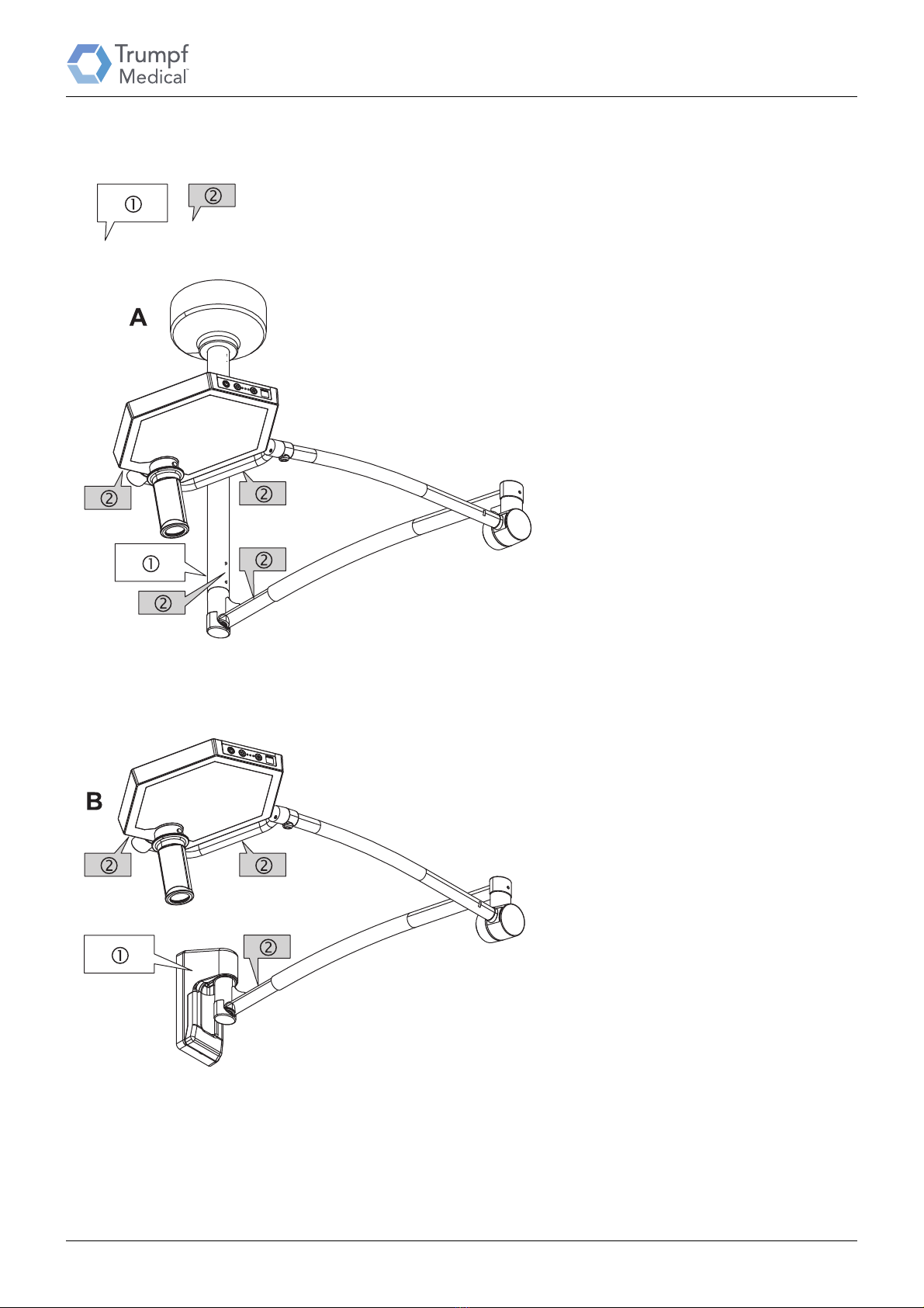
Figure 1 4.1 Use of serial numbers and
device labels
A lighting system is identified by its device
label and serial numbers.
• The device label 1 contains the specific
device data and also the main serial
number.
• The main serial number characterises an
entire device in an order-specific manner.
The main serial number also enables
components which do not have a serial
number themselves to be identified by
Trumpf Medical Customer Service,
permitting the correct spare parts to be
supplied.
• The serial numbers 2 identify the
individual components of a device.
4.1.1 Markings on the ceiling-
mounted version
A: Ceiling-mounted version
• The device label 1 with the main serial
number on the ceiling conduit.
• Serial numbers 2 of the individual
components are provided at:
–Light head
–Quarter bracket
– Ceiling conduit
– Boom with spring arm
4.1.2 Markings on the wall-mounted
version
B: Wall-mounted version
• The device label 1 with the main serial
number on the cover of the wall support.
• Serial numbers 2 of the individual
components are provided at:
–Light head
–Quarter bracket
– Boom with spring arm
This manual suits for next models
3
Table of contents
Other Trumpf Medical Equipment manuals


Popular Medical Equipment manuals by other brands


Getinge
Getinge Arjohuntleigh Nimbus 3 Professional Instructions for use

Mettler Electronics
Mettler Electronics Sonicator 730 Maintenance manual

Pressalit Care
Pressalit Care R1100 Mounting instruction

Denas MS
Denas MS DENAS-T operating manual

bort medical
bort medical ActiveColor quick guide

AccuVein
AccuVein AV400 user manual


