TSI Instruments WC-15 Manual

WC-15 WHEEL CLEANER
13" – 20" DIA x UP TO 12-1/2" WIDE RIM
READ INSTRUCTIONS THOROUGHLY BEFORE OPERATING
OPERATING AND MAINTENANCE INSTRUCTIONS
800.223.4540
3451 S. 40th Street
Phoenix, AZ 85040
602.437.5020
www.tsissg.com
Fax 602.437.5025
MADE IN USA
February 12, 2014

PRINCIPLE OPERATING FEATURES
WARNING: Only Personnel Trained in Operation of the WC-15
should Operate This Machine.
Thoroughly Read All Safety and Operating Instructions
Before Using This Machine. Observe all precautionary
safety decals and wear protective eyewear.
General: Do Not Allow Water or Moisture to come into contact with
Electrical Motor, Electrical Power System or any
Electrical Components.
Disconnect Electrical Power Supply before any
Maintenance.
Electric Power:
The WC-15 requires 230 volt, 30-amp, 1 phase
60 Hz service.
CAUTION: Operation of this machine for use other than cleaning
steel or aluminum tire rims is strictly prohibited.
Page 2
SAFETY INSTRUCTIONS
Access
Door
Rotate
Motor
Handle
Pivot
Motor
Handle
Fig. 1
ON / OFF
Switch

SET-UP INSTRUCTIONS
Page 3
OPERATING INSTRUCTIONS
1. Place unit on flat surface. Adjust the (4) set screws until level.
2. Plug electric cord into a 230 Volt, 30 Amp, single phase, 3 prong
grounded power source.
3. The WC-15 Wheel Cleaner is greased and lubricated prior to shipping
and upon set-up it is ready for use.
Prior to each use rotate motor away from brushing area before putting a
rim on the rubber drive rollers.
Open access door
and place rim on the
two rubber rollers up
against the spacer
guides.
Close access door.
Turn ON unit.
Fig. 2
Whether the rim is steel or aluminum, severely corroded to mildly corroded,
the applied force of the wire wheel brush contacting the rim needs to be
taken into consideration. Too much force could cause damage to an
aluminum rim, the unit motor or the wire wheel brush. Too little force will not
allow the unit to properly clean a rim.
Rotate the crank handles to engage the brush on the rim flange area being
cleaned.
Using the crank handles rotate and/or position the wire wheel brush near
the rim surface to be cleaned. (See Fig 3, page 4.)

For better vacuum performance and a cleaner shop environment it is
recommended to close the access door while cleaning wheel rims!
Page 4
Fig. 3
Make a visual inspection of the rim to determine if flange and bead seat
area are complete. When that side of the rim is finished crank motor
position away from contacting the rim and turn unit OFF.
Open access door, turn rim around and reposition on the rubber rollers up
against the spacer guides, turn unit ON and clean opposite side of the
wheel.
Repeat this process on all rim sizes ranging from 13" diameter to 20"
diameter, up to 12-1/2" wide rims.
It's recommended to occasionally clean-out the motor operating area.
Too much debris can cause excessive wear on rotating parts, flying
particles and otherwise dirt build-up on greased components which could
result in premature damage to the machine.
See Maintenance Instructions on page 5 for more specific details.

Page 5
MAINTENANCE INSTRUCTIONS
Refer to Fig. 4 to access lower chamber of unit where vacuum is located.
Remove and clean the vacuum filter and canister once a week. Dump
dirt from the canister. Tap loose debris from air filter or use an air hose to
clean out the air filter.
Replace air filter (TSI PN 12243-1) every 3 months depending on use.
Refer to vacuum maintenance instructions included with the WC-15 unit
for more detailed cleaning directions.
Facing unit an access panel is
located to the right. Turn power
OFF before opening door.
Remove the six 1/4-20 screws to
open door.
Lift vacuum out from inside the
unit. Unlatch canister from motor
housing and dispose contents.
Inspect air filter and clean as
necessary.
Replace parts in reverse order.
Fig. 4
Fig. 5
To service the chain
and other items
located below the
main unit, remove
the screws on each
end of the unit. The
red arrows in Fig. 5
show their location
on one side.
This same access is
used to add grease
to the four roller
driven bearings.

Page 6
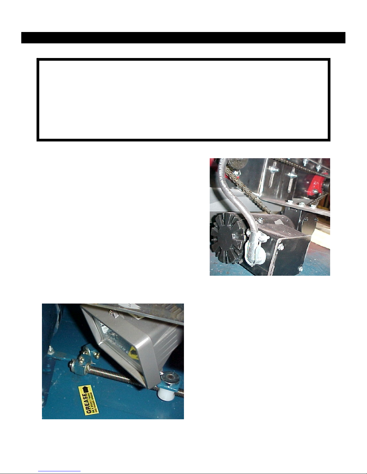
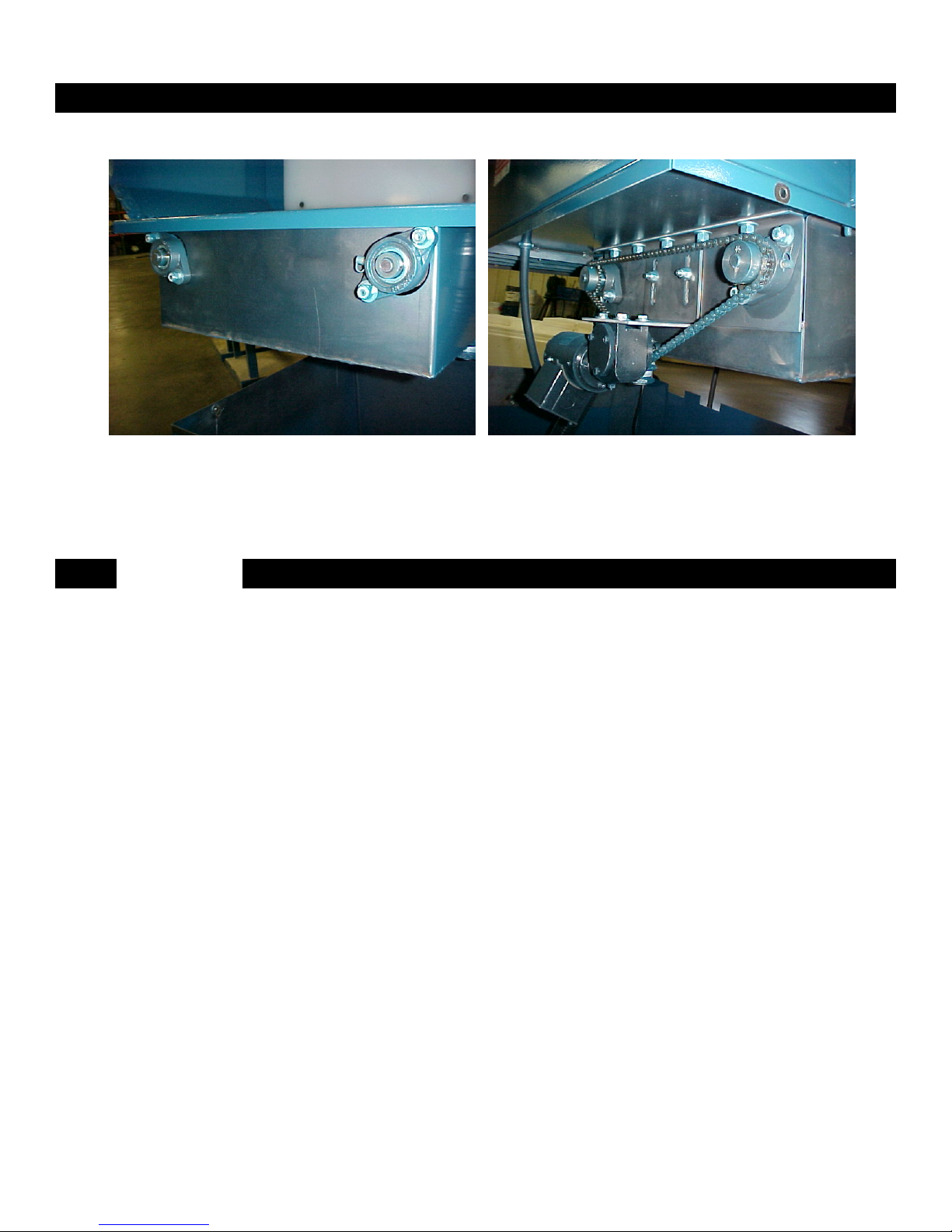
Fig. 6 shows the gear motor used to
drive the rubber coated rollers. Adjust
chain tension using the slots in the
mounting plate and the 3/8 bolts and
hardware.
Optimum chain tension is ±1/8 inch
maximum deflection between the roller
driven gear sprockets.
It is preferred to use dry spray graphite
(not oil) on chain and sprocket drive
train. Fig. 6
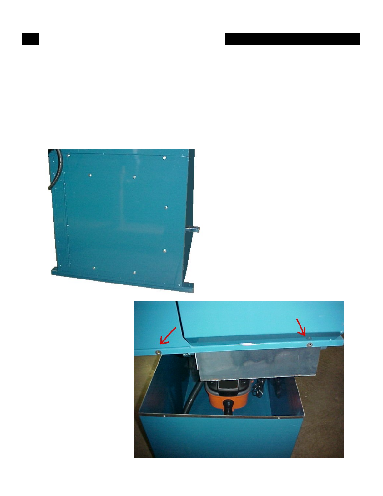
At right are two grease zerks.
Lubricate each location.
Use chassis grease on all zerks.
To replace the halogen light bulb
(TSI PN12170-1) unscrew the lens
frame and remove bulb. Make sure
unit is unplugged from electric power
source to do this.
Fig. 7
Caution
When removing top half of unit from lower section use caution not to place
hands or limbs between the two halves. Use blocks of wood or some other
item to brace each half before servicing or providing maintenance.
To replace each section be careful not to cut or pinch electric cords,
vacuum hose or other unit parts otherwise associated to the unit.

Page 7
Grease all four bearing zerks as needed. (Too much grease collects dirt.)
Fig. 8
Notes
Fig. 9

MACHINE DIMENSIONS
WC-15 WHEEL CLEANER
Tire Rim Size range: 13" to 20" Diameter x 12.5" Wide Max.
Weight: 300 Pounds
Power of Unit: Electric 230 Volt, Single Phase, 60Hz, 30 Amps
Exterior Dimensions: 48" Wide x 32" Deep x 48" Tall
SPECIFICATIONS
800.223.4540
3451 S. 40th Street
Phoenix, AZ 85040
602.437.5020
www.tsissg.com
Fax 602.437.5025
MADE IN USA
www.tsissg.com
Table of contents