Tuffcare Century Max T5248 User manual

C
Ce
en
nt
tu
ur
ry
y
T
T5
52
20
00
0
B
Ba
ar
ri
ia
at
tr
ri
ic
c
M
Ma
ax
x
H
Ho
om
me
ec
ca
ar
re
e
B
Be
ed
d
O
Op
pe
er
ra
at
ti
io
on
n
M
Ma
an
nu
ua
al
l
CENTURY MAX_T5200_V1.0

TABLE OF CONTENTS
TABLE OF CONTENTS
Table of Contents 1
Forward 2
Safety Precautions 3
Assembly Precautions 3
Product Diagram 4
Unpacking 5
Main Components 5
Product Specifications 6
Assembly
Head & Footframe 8 - 9
Mattress End Stops 9 - 10
Head & Footboard 11 - 12
Half Bed Side Rails 13 - 14
Operation
Locking/Unlocking the Caster Brakes 15
Raising/ Lowering the Bed 16
Junction Box Functions 17
Raising/Lowering the Bed Side Rails 18
Maintenance 19
Warranty 20
1 2
FORWARD
FORWARD
Congratulations on your purchase of a TUFFCARE CenturyTM
Bariatric Max bed. Our bariatric bed is a true heavy duty bed that
holds up to 1,000 lbs. It is specially engineered and designed for
Alzheimer residents or others with chronic impairments which will
reduce their degree of independence in activities of daily living.
The T5200 is a fully electric adjustable bed. The bed height, head
and foot angles functions are standard, along with trendelenburg
and reverse trendelenburg functions that are all motor controlled
with stylish hand pendant. A standard battery back up system can
last up to two hours during a power failure. The under bed LED
night light is a great feature for tip-toeing in to check on the patient
as well as safe guiding when getting out of bed in the middle of
the night. All the wonderful features make these beds the best
choice for long term care.

SAFETY PRECAUTIONS
SAFETY PRECAUTIONS
•LDo not operate your Century bariatric bed until you have read and fully
understand this manual. If you are unable to understand, contact your
equipment provider for technical support before attempting to use this bed.
•LDo not operate your bariatric bed until it is fully assembled and checked.
•LDo not place arm or head into the frame while operating. Stand clear
of device frame before operating. Operating this device with any part of
the body in the frame can result in injury.
•LDo not leave loose clothing or self in between moving parts. Keep
fingers and arms away when bed is in movement. Pinch points exist at
base of bed. USE WITH CAUTION, otherwise injury could occur.
•LDo not use if power cord is cut, frayed or loosely connected to the device.
•LDo not expose electrical components to any highly flammable items.
Power cord may be damaged by inappropriate handling, kinking, shearing
or other mechanical damages.
•LDo not position the bed to make it difficult to disconnect from supply mains.
•LDo not plug into an inadequate electrical outlet. To avoid the risk of
electrical shock, this equipment must only be connected to the supply
mains with three prong grounded outlet. The power supply cord can only
be replaced by service personnel.
•LDo not expose your institutional bed to weather or moisture.
•LDo not exceed maximum weight limit of the bed. The weight limit for
the bed is 600 lbs.
•LDo not modify this equipment without authorization of the manufacturer.
After reading the instruction, it should be put in a place where it can be
seen at any moment.
ASSEMBLING PRECAUTIONS
•LSplit frame design frame with fully loaded electronics system requires
minimum set up.
•LDo not over-tighten mounting hardware, It will cause damage to mounting
brackets.
•LBe sure that bed side rails are properly attached on main frame before
the patient is moved into the bed.
•LSecure the caster locks in place to prevent the bed moving.
•LThe medical bed should be left in its lowest position when the patient
is unattended in order to reduce RISK of injury due to falls.
3 4
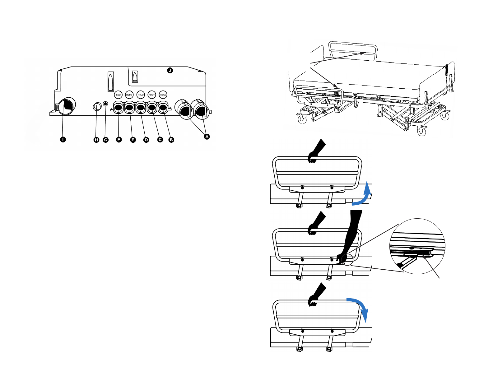
A. Head Frame B. Foot Frame
C. Headboard D. Footboard
E. Head Section Motor F. Foot Section Motor
G. Two Hi-Low Motors H. 5”Caster with Lock
I. Controller W/ Backup Battery J. Hand Pendant
K. Half Bedside Rails L. 2nd Set Half Side Rails
WARNING SAFETY ALERT LABEL
1. BEWARE OF SIDE-RAIL ENTRAPMENT
2. CRUSH HAZARD DUE TO LOW BED CLEARANCE
PRODUCT DIAGRAM
PRODUCT DIAGRAM
L WARNING SAFETY ALERT
BEWARE OF SIDE-RAIL ENTRAPMENT
Patient Entrapment with bed side rails may result in serious injury or death.
ALWAYS evaluate patient for and guard against bed rail entrapment in accordance
with medical protocols. Monitor patient frequently. Mattress MUST fit bed frame
and side rails snugly to prevent entrapment. There may be an increased risk of
entrapment when bed rails are used in conjunction with low air loss products.
Follow the Safety Warnings and Operating Instructions in the service/User’s manual.
Contact your dealer or visit WWW.TUFFCARE.COM.
A
B
C
DE
H
F
G
H
H
I
J
K
L
L WARNING Crush Hazard due to LOW BED CLEARANCE
Stay clear of frame and ensure children and pets are not under or near the frame
before lowering the bed. Beware of PINCH POINTS below deck panels, next to
fixed attachments and between moving parts.
1
2

5 6
UNPACKING
UNPACKING
A. Foot Frame B. Head Frame
C. Footboard Assembly D. Headboard Assembly
E. Mattress Stop Bars E. Bariatric Half Rails
AB
CD
EF
Remove the bed from packing case or pallet and examine
deck and frame for shipping damage. If damage is detected
in shipping, contact the freight company and file a damage
claim.
Dispose of the removed packaging at your local recycling center.
Discard the wrapper and box separately. Dispose of the end-
of-life item at a clean point.
MAIN COMPONENTS
MAIN COMPONENTS
PRODUCT SPECIFICATION

8
7
1. Position both ends of the bed so that the tabs on the headframe
section are lined up with the holders on the footframe section. The
headframe has the extruding tabs at the joint and the foot section
had the receptacle holders.
(Below illustration shows headframe on the right and footframe on
the left)
1a. Temporarily remove the top 2 sets nut and bolt on each end of
the footframe on the receptacle holders, set the nut and bolts on
the side.
(Below illustration shows headframe on the right and footframe on
the left)
ASSEMBLY
ASSEMBLY
Parts: see parts list under "Main Component" on following page
in this manual.
Tools required: two - 13mm wrench and two - 19mm wrench.
Directions for Bed Placement: A 15 foot electrical cord powers
the bed so it should be positioned within access to a AC 110 Volt
outlet. Place the bed 12" from the wall to avoid damage during
operation.
WARNING: Make sure power cords are free of pinch points.
Results of Incorrect Setup: If electrical cord is pinched in bed
mechanisms, the bed positioning may not function.
If you have questions about bed assembly or encounter a prob-
lem, call the customer service number at 800-367-6160.
LWARNING
Use only Tuffcare parts to complete this bed assembly.
1b. Llifting both the tabs and the holders, to bring them together
and slowly lower the two sections so as to interlock the tabs and
holders. The tab should set into the spacing between the holder
and the bolt. Replace the nuts and bolts that were set aside earlier.

9 10
1c. Tighten the nuts and bolts on each end
with a pair of 13mm wenchs to secure the
head and foot frames.
2a. Locate the two mattress stop mounting bolts at ends of the bed
surface.
2b. Remove the top 2 sets of nuts and bolts on each end of the
headframe on the receptacle holders, set the nut and bolts on the
side.
2c. Assemble the bolt, washer, and moon shape spacer in order
according to the diagram below, and attach the mattress stop bar
onto the frame surface.
2. The matterss stop bars are shipped cable tie on to both side of
the frame, remove them to install.
(Below illustration shows headframe on the right and footframe on
the left)

1211
3c. Push footboard down all the way until it stops, the holes on the
footboard mounting tubes and the holes on the footframe receptacle
tubes should line up. Secure the footboard by inserting the two
quick-release pins back in the holes. Repeat the same process for
the head board.
3a. First, start with the foot frame, pull out the ring grip quick-
release pins on two side of the receptacle tubes.
3b. Carefully set the mounting tubes on the board end, down the
receptacle tubes.
3d. Repeat the same process as the footboard for the headboard
to complete the assembly.
4. The two actuators on the foot frame were shipped unplunged,
they need to be plug into the junction box for the bed to function.
Locate the junction box close to the middle of the bed, on the head-
frame side.

1413
4c. Make sure the side with the black release lever faces the foot
end of the bed.
(Optional 2nd pair of side rail also need to have the lever side face
the same direction.
5d. Install the bolt and tighten into the holes while holding the nut
with your other hand.
5e. Use a pair of 19MM wrenches to tighten the bolt and nut in
order to secure the swing bars on the top head of the section
frame.
4a. The actuator plug are color coded, plug the blue plug into the
foot motor receptacles and the yellow into the hi/lo receptacles.
ASSEMBLING SWING-DOWN HALF BED SIDE RAILS
Note: Secure the caster locks in place to prevent the bed
from moving.
5a. Raise the head frame to expose the holes on top of bed frame.
5b. Position it half bedside rails’ swing bars on top of bed frame.

1615
PREPARING THE BED FOR USE
1. Make sure all of electronic components are well connected,
and all of wires are clear from moving parts.
2. Check and tighten all hardware BEFORE use.
LWARNING
The user must be assessed by a qualified professional.
Thoroughly read and fully understand the instructions in
this Owner’s Manual. If you are unable to understand,
contact your equipment provider for technical support
before attempting to use this bed.
Push down the lower pedal to LOCK the caster wheels
Push down the upper pedal to UNLOCK the caster wheels
OPERATION
OPERATION
LOCKING/UNLOCKING THE CASTER BRAKES
PENDANT FUNCTIONS
Press indicated buttons to move the bed up and (or) down.
A. Head Section
B. Foot Section
C. Head & Foot Section
D. Hi-Low
E. Trendelenburg
/Reverse Trendelenburg
F. LED Night Light ON/OFF
LWARNING DO NOT exceed the maximum weight limit of
Beds: T5248 – 800 lbs, T5254 & T5260 – 1,000 lbs.
LWARNING Operation of this device with any part of the
body in the frame can result in injury. Do not place your arm
or head in the frame while operating.
LWARNING Stand clear of device frame before operating.
LWARNING Rotating Parts. Keep hands and fingers
away when mechanism is moving.
LWARNING Keep hands and fingers away when bed is
in movement to avoid pinching.
LWARNING Electrical hazards may occur if the device
is plugged into an inadequate electrical outlet. To avoid
electrical shock hazard, make sure that the bed is plugged into
a grounded 110 Volt outlet. Before operating, make sure
casters are in their proper operating position. On the hand
Controller Functions, press the button indicated to move bed.
RAISING/LOWERING THE BED

1817
RAISING UP & LOWERING DOWN BEDSIDE RAILS
Swing up the bed side rail to
the upper position, then slide
and push down to ensure the
lock is engaged.
Note: There is only one
upper locking position for
Tuffcare bed side rails.
Press Release Trigger
Lower bedside rail from high
to low position.
BEDSIDE
RAILS
JUNCTION BOX FUNCTIONS
Control of all of electronic components.
A. Hand Pendant/Control Panel
B. Head Motor
C. Foot Motor
D. Hi-Low Motor (installed on Foot Main Frame)
E. Hi-Low Motor (installed on Head Main Frame)
F. LED Night Light
G. Battery Indicator Light (green when charged)
H. Fuse Box
I. Power Cord with Ground connection
J. Built-in Backup Re-chargeable Battery
Use built-in rechargeable battery backup power for emergency
operation. Note: The indicated light will be turned green when
battery is fully charged.

LIMITED WARRANTY
LIMITED WARRANTY
The warranty below has been drafted to comply with Federal Law applicable
to products manufactured after July 4, 1975. This warranty is extended only
to the original purchaser/consumer (or dealer non-consumer who does not
buy for resale).
Tuffcare®warrants that it’s Centrury Bariatric Max beds will be free from
defective workmanship and materials for a period of three (3) years following
the date of original manufacture with the following exceptions: All welds are
warranted for the life of the bed. Electronics on the beds are warranted for
one (1) year. The warranty period commences on the original manufacture
date. If within such warranty period any such product proven to Tuffcare®
satisfaction to be defective, such product will be repaired or replaced at
Tuffcare®option.
Tuffcare®sole obligation and your exclusive remedy under this warranty
shall be limited to such repair and/or replacement. This warranty does not
include any labor charges incurred in replacement parts installation. Freight
charges to the factory are at the expense of the consumer or seller. Return
freight charges will be prepaid by Tuffcare®. For warranty service, please
contact the authorized dealer from whom you purchased your Tuffcare®
products. In the event that you do not receive satisfactory warranty service,
please write directly to Tuffcare®: 4977 La Palma Ave, Anaheim, California,
92807. DO NOT RETURN PRODUCTS WITHOUT PRIOR AUTHORIZATION.
LIMITATIONS AND EXCLUSIONS: The foregoing warranty shall not apply
to products subjected to negligence, abuse, misuse, improper operation,
improper maintenance, improper storage or damages beyond Tuffcare®
control. The evaluation will be solely determined by Tuffcare®. The warranty
shall not apply to problems arising from normal wear, or failure to follow
instructions, or if parts are not manufactured by Tuffcare®, or do not comply
with original equipment specifications that are added to Tuffcare®product.
THE FOREGOING WARRANTY IS EXCLUSIVE AND IN LIEU OF ALL
OTHER WARRANTIES, INCLUDING BUT NOT LIMITED TO THE IMPLIED
WARRANTIES OF MERCHANTABILITY AND FITNESS FOR A PARTICULAR
PURPOSE AND SHALL NOT EXTEND BEYOND THE DURATION OF THE
EXPRESS WARRANTY PROVIDED HEREIN. TUFFCARE®SHALL NOT
BE LIABLE FOR ANY CONSEQUENTIAL OR INCIDENTAL
DAMAGES WHATSOEVER.
This warranty gives you specific rights and you may also have other legal
rights which vary from state to state. Some states do not allow the exclusion
or limitations of incidental or consequential damage, or limitation on how
long an implied warranty
2019
MAINTENANCE
MAINTENANCE
CLEANING THE BED
• The Bed can be cleaned with non-abrasive cleaners.
• Inspect and clear casters of debris, making sure that
the wheels roll, and they swivels smoothly.
DETECTING WEAR AND DAMAGE
• Check monthly that all screws are tight and have not
loosened.
• Check monthly for damaged or exposed wires on the
electrical components.
• Inspect monthly for signs of cracking, fraying, or any
deterioration.
• Contact your equipment provider for replacement of
any defective parts immediately and ensure that the
bed is not used until repair job is completed.
LUBRICATING THE BED
• A light grease lubricant may be applied to the ball
bearing and swivel of the casters every three months.
PERFORMING REGULAR MAINTENANCE
• Regular maintenance of the bed and accessories are
required to ensure proper operation. The casters and
axle bolts are to be checked for proper tightness.
This manual suits for next models
3
Table of contents
Other Tuffcare Medical Equipment manuals

Tuffcare
Tuffcare T4000 User manual

Tuffcare
Tuffcare T2020 User manual

Tuffcare
Tuffcare Century T7036 User manual

Tuffcare
Tuffcare T8036 User manual

Tuffcare
Tuffcare Rhino P110 User manual

Tuffcare
Tuffcare Century TLN3120 User manual

Tuffcare
Tuffcare Rhino P420 User manual

Tuffcare
Tuffcare T8036 User manual

Tuffcare
Tuffcare Rhino P420 User manual