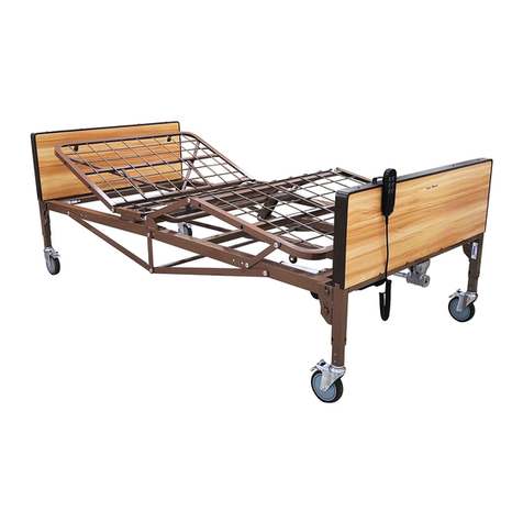
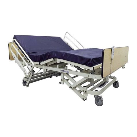
Tuffcare T2020 User manual

User Manual
SEMI-ELECTRIC HOMECARE BED
Model: T2020 ( Dual Motors), T2010 (Single Motor)
For more information regarding Tuffcare Products & Services, please visit www.tuffcare.com or call 800-367-
6160.
Part#:070714JC-2020 /T2010Version No:002

Table of Contents
Forward....................................................................1
Safety Precautions ...............................................2-3
Main Components....................................................4
Assembly Instructions ..........................................5-8
Operation Instructions..............................................9
Preventative Maintenance .....................................10
The Disposal of the Bed & Accessories ……..……11
Product Specification…….……………………...…..12
Warranty Information................................ Back Cover

Forward
Congratulations on your purchase of a Tuffcare® homecare bed! Our homecare
bed is engineered and designed with durability & easy maintenance in mind. Read
through this manual and get acquainted with your institutional bed. Follow the
maintenance schedule to ensure proper function of your bed.
A. B. C. D. E. F. G. H. I. J.
1. SINGLE MOTOR ( For T2010 )
A. HEAD BOARD F. HI-LO HAND CRANK
B. HEAD FRAME G. HEAD MOTOR ( For T2020 )
C. FOOT FRAME H. FOOT MOTOR ( For T2020)
D. FOOT BOARD I. POWER CORD
E. PENDANT CONTROL J. CASTER BRAKE LEVER
-1-

Safety Precautions
• Keep fingers and arms away when mechanism is moving. Rotating Parts.
• Pinch Point. Keep fingers and arms away when bed is in movement.
• Do not operate your institutional bed until you have read and fully understand this manual.
• Do not operate your institutional bed until the institutional bed is fully assembled and checked.
• Do not expose your institutional bed to weather or moisture.
• Do not leave loose clothing or self in between moving parts.
• Do not expose electrical components to any highly flammable items.
• Do not use your institutional bed with an improper mattress.
• Do not use if the power cord is cut, frayed or loosely connected to the device.
• Electrical hazard may occur if device is plugged into an inadequate electrical outlet.
Make sure the bed is plugged into a grounded 110 volt outlet, to avoid electrical shock hazard.
WARNING: To avoid risk of electric shock, this equipment must only be connected to a supply mains with
protective earth
Check back-up batteries every 3 months and replace new back-up batteries yearly.
Remove back-up batteries out of battery pack within 72 hours when equipment won’t be used.
WARNING: Pre-installing the back-up batteries into the pack will only drain the batteries and corrode the
contain points.
Do not to position THE BED to make it difficult to disconnect from supply mains
WARNING: Do not modify this equipment without authorization of the manufacturer
After finish reading the instruction, it should be put on the place where can be seen at any moment.
Warning: Do not modify this equipment without authorization of the manufacturer; the POWER SUPPLY
CORD can only be replaceable by SERVICE PERSONNEL.
Warning: the MEDICAL BED should be left in its lowest position when the PATIENT is unattended in order
to reduce RISK of injury due to falls.
Warning: POWER SUPPLY CORD may be damaged caused by inappropriate handling, e. g. by kinking,
shearing or other mechanical damages
Maximum Back Angle to horizontal is 65 degree. Maximum Knee Angle to horizontal is 43 degree.
Maximum Knee to Leg Angle is 120 degree.
Precautions shall be taken to avoid squeezing when routing cables from other equipment.
In order to act immediately in the case of hazard, the emergency position(s) stop button is located on the
side of hand pendent.
-2-

Symbols Description
Manufacture Name & Address
Environmental Conditions of Temperature for
Shipping & Storage
Environmental Conditions of Humidity for Shipping
& Storage
Environmental Conditions of Atmospheric Pressure
for Shipping & Storage
Caution for shipping & storage package
“ Fragile”, “ Handle with Care”, “Keep Dry”
CE Certification Logo
Attention
Double Isolation
“BF” Symbol, indicate this product is according to
the degree of protection against electric shock for
type BF equipment
CAUTION, read the instruction before use
IPX4 Technical IP Rating
SN Manufacture Serial Number
-3-

Main Components
Before unpacking, inspect for any obvious damage to the carton and
contents. If damage is found contact your dealer. The homecare bed
comes packaged in two cartons. Carefully unpack the components.
When removing the head and foot frame out of the box, do not separate
the two as there’s a motor cord attaching them. The Hi/Lo shaft is cable
tied to the bottom part of foot frame. Detach it and remove all packing
material. Semi electric homecare bed contains five main parts.
STANDARD COMPONENTS OPTIONAL COMPONENTS
1, Head /Foot Board 5, Half Side Bed Rails
2, Head/Foot Frame with Motor ( FOR 2020) 6, Full Side Bed Rails
3, Single Motor ( FOR 2010) 7, Standard Mattress
4, Hi-Lo Drive Shaft 8, Pressure Reduction Mattress
-4-

Assembly Instruction
1. First assemble the foot & head frame. It can be assembled with the foot
section (A) upside down, flat on the floor with the metal rods facing the floor,
or with the foot section on its side, whichever is easier. Motor or cranks should
be on the left side.
Figure 1.1 Figure 1.2
2. Temporarily remove the 2 hex bolts and nuts located in the middle joint of
the head frame. Pick up the head frame (B) and at a 75% angle fit the frame
hooks onto the two shoulder rivets on the side rail of the foot frame. Rotate
the head frame until it is lined up with the foot frame. Lock the hooks securely
onto the shoulder rivets.
Figure 2.1 Figure 2.2
-5-

3-1. For T2020 - Then rotate the bed to have the top setting facing up. Line up the two holes
on both ends of the frame, and re-secure the hex bolts in middle of frame on both sides.
3-2. For T2020 - Connect both the head and foot motor drive shafts to the lifting arms. Start
with the drive shafts on head frame A, and work your way to the one on foot frame B.
A. B.
Figure 3-1 Figure 3-2
3-3. For T2020 - Pull to release the cotter pin from the clevis holding pin. Align the drive
shaft hole with the oval holes on the lifting plate. Re-secure the holding pin on
both sides of the left plate. Then reattach the cotter pin to lock.
Continued on Step 5
Figure 3-3 Figure 3-3
-6-

4-1, For T2010 – Continued from Step 2, pull to release the cotter pin from the clevis holding
pin. Align the drive shaft hole with the holes on the lifting plate. Re-secure the holding pin on
both sides of the left plate. Then reattach the cotter pin to lock.
Repeat on Head Section.
Figure 4 -1 Figure 4-1
4-2, For T2010 – Installation of Motor and Hand Pen with bed frame:
A1, Slide locking covers (Foot and head section) out of motor.
A2, Align the opening on the head end of the motor with the flange on the head section of the
bed and insert the flange into the motor compartment. Then, with the palm of your hand, snap
the motor flush to the actuator bar.
Repeat on Foot Section.
Figure A-2 Figure A-3
A3, After the motor is installed, slide locking covers back on motor.
-7-

A4, Plug hand pendant into motor.
Figure A-4 Figure 4-3
4-3. For T2010 - Then rotate the bed to have the top setting facing up. Line up the two holes
on both ends of the frame, and re-secure the hex bolts in middle of frame on both sides.
Continued on Step 5
5. With the two frames connected and spring section of the frames facing up, slide the head
board and the foot board onto the frame corner plate rivets. All head boards are taller than the
foot boards.
Figure 5.1 Figure 5.2
6. The Hi/Lo shaft has 4 hole positioning adjustment on it. It’s designed to be a universal fit
with other style beds. For semi electric beds use the 2nd hole on the outer tube to line up with
the locking pin on the inner tube.
-8-

Figure 6
7. The hi/lo shaft has one end with a short shaft that is spring-loaded. Connect the spring-
loaded end of the long drive shaft onto the hand crank shaft located on the foot board, pull the
shaft towards bed end, and connect the other end of the drive onto the shaft, on the T-shape
gear box of the head board end.
Figure 7
8. A spare battery backup pack is outfitted in case of power failure.
For T2020 - It is located near the main control unit on the foot frame.
For T2010 - It is located on motor next to power cord.
The power packup is designed to raise and lower the bed up for emergencies use only.
Figure 8.1 (T2020) Figure 8.2 (T2010)
-9-

9. For T2020 The battery pack uses three household 9 volt batteries (not supplied).
For T2010 The battery pack uses one household 9 volt batteries (not supplied).
It is important to keep the battery pack vacant until the bed is needed. Pre-installing the
batteries into the pack will only drain the batteries and corrode the contact points.
Figure 9 (T2020)
-10-

Operation Instructions
1. Make sure the bed power cord is plugged into a grounded 110 Volt AC outlet.
• Operating this device with any part of the body in the frame can result in injury. Do not place
arm or head into the frame while operating. Stand clear of device frame before operating.
• Rotating Parts. Keep fingers and arms away when mechanism is moving.
•Pinch Point. Keep fingers and arms away when bed is in movement.
• Electric Powered Mechanism. Electrical hazard may occur if device is plugged into an
inadequate electrical outlet. To avoid electrical shock hazard, make sure the bed is plugged
into a grounded 110 Volt outlet.
2. Before operating, make sure casters are in their proper operating position. Hand Controller
Functions, press button indicated to move bed.
3. To install and raise/lower optional side rails: Slide rails into brackets using pin lock
adjustment.
4. The bed is operated by hand crank and standard 4 function pendant.
A.
* Semi electric bed:
To raise the bed, crank clockwise on point A.
To lower the bed, crank counter clockwise on point A.
* To raise or lower head section:
To raise head section, press head up button.
To lower head section, press head down button.
* To raise or lower foot section:
To raise foot section, press foot up button.
To lower foot section, press foot down button.
-11-

Preventative Maintenance
1. Cleaning – Tuffcare recommends the following cleaning procedures be conducted between
uses and at least one a year.
1.1, Unplug the power code of electric beds before performing maintenance.
1.2, Wide down with disinfectant. Allow to dry completely.
Caution: Avoid spraying water directly into the electric components. Otherwise, damage to
electric components may occur.
2, Mechanical Inspection and Maintenance-
2.1, Inspect all bed components for damage or excessive wear.
2.2, Inspect pull tubes and mounting hardware for bending, damage or excessive wear.
2.3, Inspect all bolts and rivets to ensure that they are securely tightened and functioning
properly.
2.4, Inspect sleep surfaces to ensure all links are intact.
2.5, Inspect caster wheels to ensure they look and roll properly.
3, Electrical Inspection and Maintenance –
3.1, Inspect all electrical components for damage or excessive wear.
3.2, Check pendent, power code and motor cables for chafing, cuts or excessive wear.
3.3, Make sure all of plugs are fully attached and free of damage.
3.4, Check all functions working properly.
3.5, Unplug power cord for testing back-up power –
3.5.1, Install three 9Volt household batteries (not supplied) into the back-up battery pack.
3.5.2, Check all functions working properly with back-up power.
3.5.3, Remove the back-up batteries out of battery pack immediately after testing and re-plug
power cord for normal used.
3.6, Check all functions working properly after re-plug power cord.
4, To Maximize Services Life – To ensure maximum life of your bed, follow all of warning and
cautions in the User Manual and maintain your bed with care – a thorough inspection should
be conducted as follow:
4.1, Run the bed frame to either the highest or lowest position once a day.
4.2, Observe bed operation and report any discrepancies or problems to service personnel.
4.3, Check and tighten all tubes and mounting hardware monthly.
4.4, Check and tighten all electric wires and cables are properly connected monthly.
4.5, Lubricate pivot point, pins and bolts every 2 months.
WARNING: Possible Shock Hazard. All electric components only can be replaced by
service personnel.
-12-

The Disposal of the Bed & Accessories
When the bed and accessories are broken or no longer be useable, the bed and accessories
may be discarded for recycle. Please contact your provider or Tuffcare at 800-367-6160 for
more detail.
-13-

Product Specification
Model & Standard
Features
Century Semi Electric – T2020/T2010
36” x 80” Sleep Surface
Overall Width: 36 inches : Overall Length: 88 inches
Max. patient weight 360 lbs
Safety working load 360 lbs
Rating 3.6 AMP(120V), 60 Hz
Classification ClassII, Type B
Mode of Operation 10% Maximum Duty Cycle 2 Minutes on/18 Minutes off
Environmental
Conditions of Operating
Ambient Temperature: 10 to 40 C.
Relative Humidity: 30% to 75% Non-Condensing
Atmospheric Pressure: 700 to 1060 hPa
Environmental
Conditions of Shipping &
Storage
Ambient Temperature: -4.4 to 70 C. Relative
Relative Humidity: 10% to 95%
Atmospheric Pressure: 500 to 1060 hPa
Application environment
category according to
IEC 60601-2-52
Height adjustable range Min 385 mm to Max 585 mm
Maximum mass (in kg)
of the MEDICAL BED 25 Kg
We can make available on request circuit diagrams, component part lists, descriptions, calibration
instructions, or other information that will assist SERVICE PERSONNEL to repair those parts, please
contact the manufacturer, details see the contact information.
-14-

This product needs special precautions regarding EMC and needs to be installed and put into service according to the EMC information
provided, and this unit can be affected by portable and mobile RF communications equipment.
2) * Do not use a mobile phone or other devices that emit electromagnetic fields, near the unit. This may result in incorrect operation of the
unit.
3) Caution: This unit has been thoroughly tested and inspected to assure proper performance and operation!
4) * Caution: this machine should not be used adjacent to or stacked with other equipment and that if adjacent or stacked use is necessary,
this machine should be observed to verify normal operation in the configuration in which it will be used
Guidance and manufacture’s declaration – electromagnetic emission
The T4020 is intended for use in the electromagnetic environment specified below. The customer of the user of the
T4020 should assure that it is used in such an environment.
Emission test Compliance Electromagnetic environment – guidance
RF emissions
CISPR 11
Group 1
The T4020 use RF energy only for its internal function.
Therefore, its RF emissions are very low and are not
likely to cause any interference in nearby electronic
equipment.
RF emission
CISPR 11
Class B
The T4020 is suitable for use in all establishments,
including domestic establishments and those directly
connected to the public low-voltage power supply
network that supplies buildings used for domestic
purposes.
Harmonic emissions
IEC 61000-3-2
Class A
Voltage fluctuations/
flicker emissions
IEC 61000-3-3
Complies

Guidance and manufacture’s declaration – electromagnetic immunity
The T4020 is intended for use in the electromagnetic environment specified below. The customer or the user of T4020
should assure that it is used in such an environment.
Immunity test IEC 60601 test level Compliance level Electromagnetic environment -
guidance
Electrostatic
discharge (ESD)
IEC 61000-4-2
±6 kV contact
±8 kV air
±6 kV contact
±8 kV air
Floors should be wood, concrete
or ceramic tile. If floor are
covered with synthetic material,
the relative humidity should be at
least 30%.
Electrical fast
transient/burst
IEC 61000-4-4
±2 kV for power supply
lines
±1 kV for input/output
lines
±2kV for power
supply lines
±1 kV for input/output
lines
Mains power quality should be
that of a typical commercial or
hospital environment.
Surge
IEC 61000-4-5
± 1 kV line(s) to line(s)
± 2 kV line(s) to earth
±1 kV differential
mode
±2 kV common mode
Mains power quality should be
that of a typical commercial or
hospital environment.
Voltage dips, short
interruptions and
voltage variations on
power supply input
lines
IEC 61000-4-11
<5% UT
(>95% dip in UT)
for 0.5 cycle
40% UT
(60% dip in UT)
for 5 cycles
70% UT
(30% dip in UT)
for 25 cycles
<5% UT
(>95% dip in UT)
for 0.5 cycle
40% UT
(60% dip in UT)
for 5 cycles
70% UT
(30% dip in UT)
for 25 cycles
Mains power quality should be
that of a typical commercial or
hospital environment. If the user
of the T4020 requires continued
operation during power mains
interruptions, it is recommended
that the T4020 be powered from
an uninterruptible power supply
or a battery.

<5% UT
(>95% dip in UT)
for 5 sec
<5% UT
(>95% dip in UT)
for 5 sec
Power frequency
(50Hz/60Hz)
magnetic field IEC
61000-4-8
3 A/m 3 A/m Power frequency magnetic fields
should be at levels characteristic
of a typical location in a typical
commercial or hospital
environment.
NOTE UT is the a.c. mains voltage prior to application of the test level.

Guidance and manufacture’s declaration – electromagnetic immunity
The T4020 is intended for use in the electromagnetic environment specified below. The customer or the
user of the T4020 should assure that it is used in such an environment.
Immunity
test
IEC 60601 test
level
Compliance
level Electromagnetic environment - guidance
Conducted RF
IEC 61000-4-6
3 Vrms
150 kHz to 80 MHz
3 Vrms
Portable and mobile RF communications equipment
should be used no closer to any part of the T4020,
including cables, than the recommended separation
distance calculated from the equation applicable to the
frequency of the transmitter.
Recommended separation distance
Where P is the maximum output power rating of the
transmitter in watts (W) according to the transmitter
manufacturer and d is the recommended separation
distance in metres (m).
Field strengths from fixed RF transmitters, as determined
by an electromagnetic site survey,a should be less than the
compliance level in each frequency range.b
Interference may occur in the vicinity of equipment marked
with the following symbol:
Radiated RF
IEC 61000-4-3
3 V/m
80 MHz to 2.5 GHz
3 V/m
This manual suits for next models
1
Table of contents
Other Tuffcare Medical Equipment manuals

Tuffcare
Tuffcare T8036 User manual

Tuffcare
Tuffcare Rhino P110 User manual

Tuffcare
Tuffcare T8036 User manual

Tuffcare
Tuffcare T4000 User manual

Tuffcare
Tuffcare Century Max T5248 User manual

Tuffcare
Tuffcare Century T7036 User manual

Tuffcare
Tuffcare Rhino P420 User manual

Tuffcare
Tuffcare Rhino P420 User manual

Tuffcare
Tuffcare Century TLN3120 User manual
Popular Medical Equipment manuals by other brands

Fresenius Medical Care
Fresenius Medical Care bibag V2.0 Technician manual

Petermann
Petermann PM-7010 manual

HemoCue
HemoCue Hb 801 operating manual

OAKWORKS
OAKWORKS ProLuxe Series Instruction & maintenance manual

DHG
DHG RoMedic LiftSeat Instructions for use

Olympus
Olympus EVIS EUS EU-ME2 Quick reference guide