Tulsa RUFNEK 20 User manual

SEL-0045-001.DOC
REV-0 July 2020
RUFNEK 20
AND
MODEL 23
SERVICE MANUAL
GENERAL INFORMATION .......................................................................................................................... 4
INTRODUCTION AND THEORY OF OPERATION .................................................................................................................4
ASSEMBLY NUMBER EXPLANATION ...................................................................................................................................4
WINCH BREAK-IN ..................................................................................................................................................................4
MODEL CODES ........................................................................................................................................... 5
MAINTENANCE............................................................................................................................................ 6
OIL LEVELS............................................................................................................................................................................7
BRAKE ADJUSTMENT ...........................................................................................................................................................8
DISASSEMBLY ............................................................................................................................................ 9
RUFNEK 20 BRAKE DISASSEMBLY......................................................................................................................................9
MODEL 23 BRAKE DISASSEMBLY........................................................................................................................................10
CLUTCH AND DRUM DISASSEMBLY....................................................................................................................................11
GEARBOX DISASSEMBLY.....................................................................................................................................................12
GEAR INSPECTION INSTRUCTIONS ....................................................................................................................................13
ASSEMBLY ................................................................................................................................................ 14
GEARBOX ASSEMBLY ..........................................................................................................................................................14
MODEL 23 BRAKE ASSEMBLY..............................................................................................................................................15
RUFNEK 20 BRAKE ASSEMBLY............................................................................................................................................15
CLUTCH AND DRUM ASSEMBLY..........................................................................................................................................16
TROUBLESHOOTING................................................................................................................................ 16
BILL OF MATERIAL................................................................................................................................... 16
TORQUE SPECIFICATIONS CHART ........................................................................................................ 16
CLUTCH INSPECTION .............................................................................................................................. 16
ISOMETRIC DRAWING.............................................................................................................................. 16
RUFNEK BRAKE, HYDRAULIC MOTOR, & CLUTCH POSITION INDICATOR...................................... 16
DESIGN SERIES 001

2
FAILURE TO HEED THE FOLLOWING WARNINGS MAY RESULT IN
SERIOUS INJURY OR DEATH.
The safety of the winch operator and ground personnel should always be of great
concern, and all necessary precautions to insure their safety must be taken. The
primary mover and the winch must be operated with care and concern for the
equipment and the environment and with a thorough knowledge of the equipment and
its performance capabilities must be understood. These general safety guidelines are
offered, however local rules and regulations or national standards may also apply.
Recommended references are, but not limited to, ANSI B30, OSHA 1910, AWS D 14.3,
and SAE J706.
Additional information can be found at http://www.team-twg.com/TulsaWinch/
Mounting:
Winch mounting must be secure and able to withstand the applied loads.
•The stability of the mounting system must be approved by a qualified person.
•All welding should also be done by a qualified person.
•Winch mount must be flat so as not to induce binding.
•The flatness must not exceed 1/16 inch across the mounting surface of the winch
itself.
Guards must be placed on all open drives in the case of mechanical winches.
Insure that all hydraulic hoses, valves and fittings are rated to winch manufacturer’s
operating pressures.
Relief valves should be set to winch manufacturer’s specifications.
Insure that all PTO’s and drivelines are sized appropriately for the winch manufactures
speed and torque specifications.
Indicates an imminently hazardous situation
which, if not avoided, will result in death or serious
injury.
Indicates a potentially hazardous situation which,
if not avoided, could result in death or serious
injury.
Indicates a potentially hazardous situation which,
if not avoided, may result in minor or moderate
injury or property damage.
Indicates information or a company policy that
relates directly or indirectly to the safety of
personnel or protection of property.

3
Operator:
Must read and understand the operating and service manual.
Both the SERVICE MANUAL and OPERATING AND MAINTENANCE MANUAL
are available online at http://www.team-twg.com/TulsaWinch/
Must never lift or move people with this winch.
This winch is not designed or intended for any use that involves moving people.
Must stay clear of the load at all times.
Ground personnel should remain a safe distance from the load and winch cable
at least 1 ½ times the length of cable measured from the winch to the load.
Must stay clear of the cable at all times.
A broken cable can cause serious injury or death.
Must avoid shock loads.
Shock loads can impose a strain on the winch that can be many times the design
rating.
Must be aware of the fleet angle of the winch.
All loads should only be pulled with the load line perpendicular to the drum shaft,
this is to avoid excessive stresses on the winch and will help prevent the cable
from building on one side of the drum flange.
Must wear personnel protective equipment (PPE) if required.
Check the local, state and federal regulations for compliance.
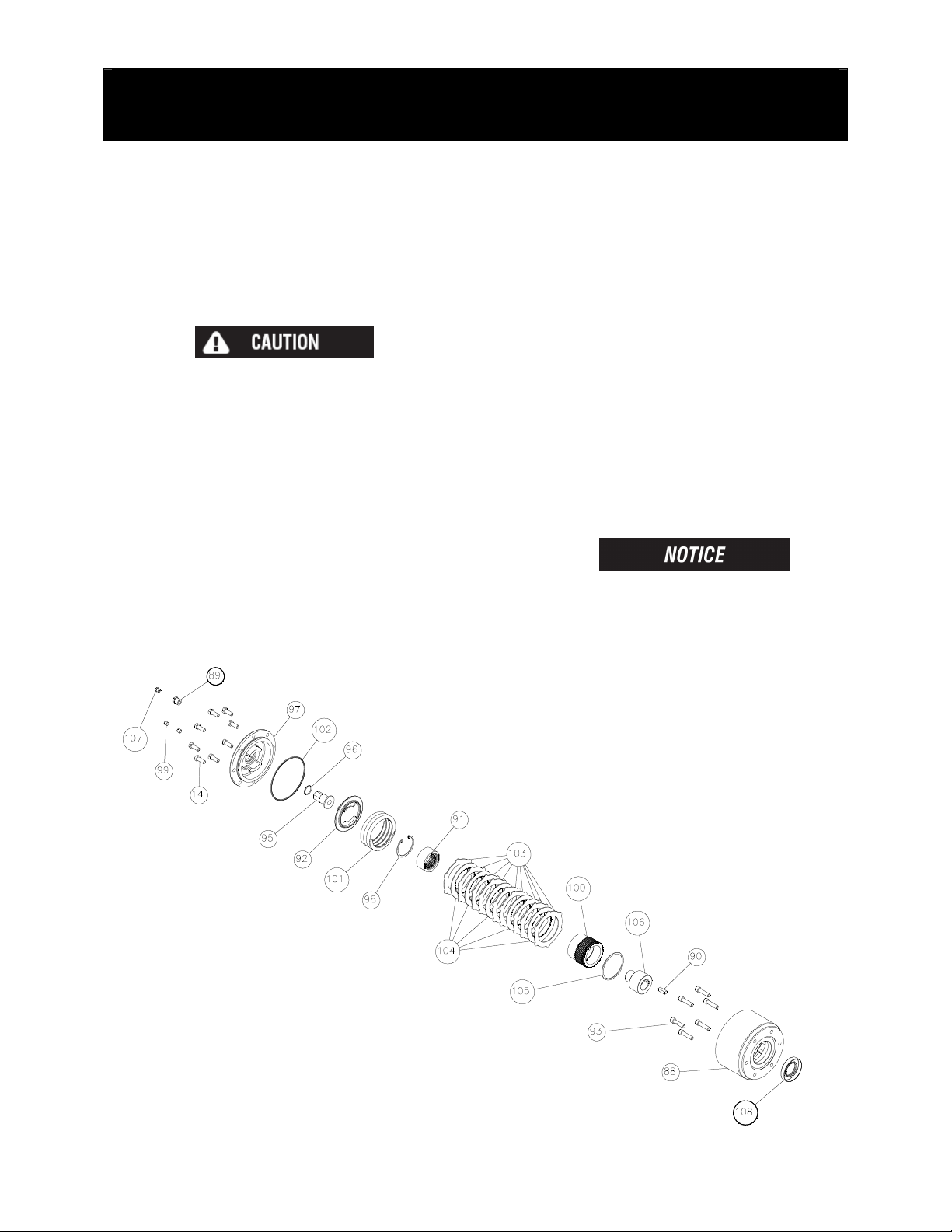
Must insure that the drum clutch is fully engaged before hoisting.
A visual inspection of the drum clutch engagement is required before each
winching operation.
Must rig all loads secure before winching.
Pull the load line taut and inspect the condition of load for stability.
Must inspect the drum brake if equipped.
The drum brake is not a load holding device it is design to prevent over spooling
of the drum and causing bird nesting of the cable on the drum. Inspect the brake
for wear of the lining and the actuation method.
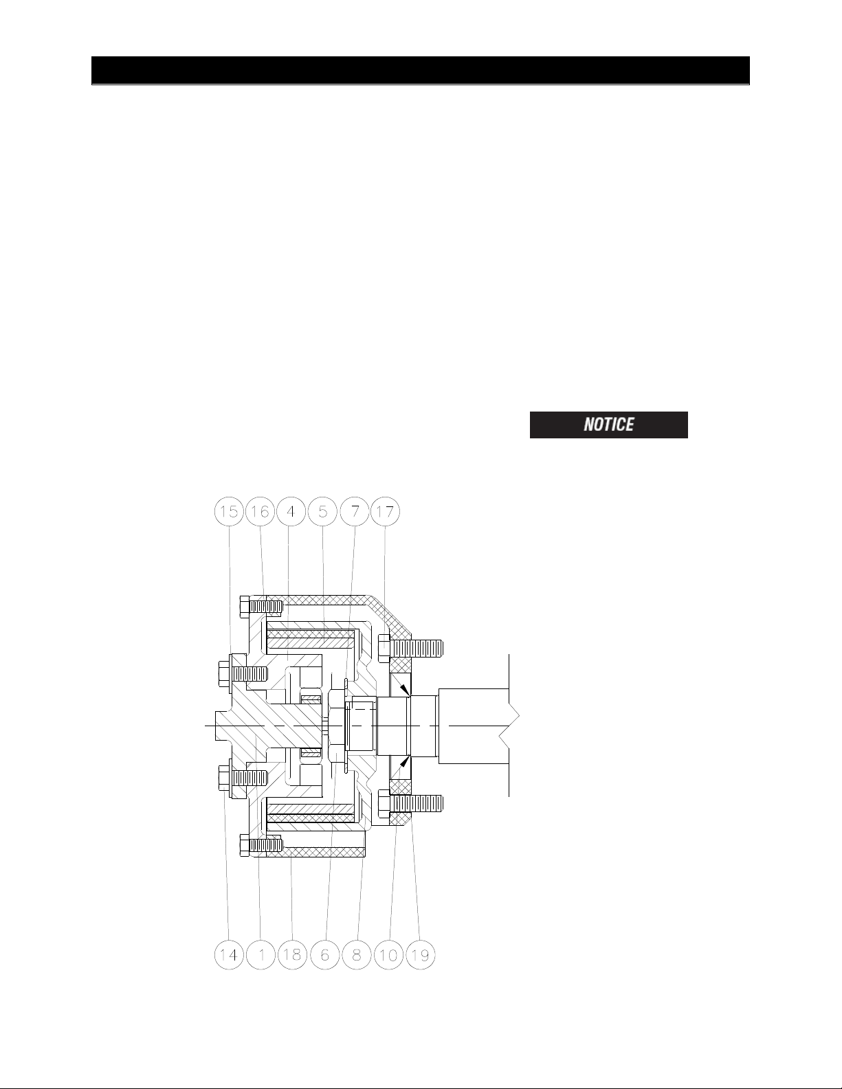
Must inspect the load control brake.
These winches can be equipped with two (2) forms of dynamic braking. The
worm brake is one method and is adjustable for pay-out load control. Before a
load is handled the load should be pulled tight and stopped to check this brake.
The second method is a hydraulic lowering control that is not field adjustable.
The same method should be used to check this brake.
Operation:
•All winch controls must be well marked for function to avoid confusion.
•Insure that the PTO is disengaged when the winch is not in use.
•All winch controls must be located to provide the operator with a clear view of the
load.
•The clutch must be inspected daily for proper operation.
•The winch cable should be inspected daily for serviceability.
•A minimum of five wraps of tightly wound cable must remain on the drum.

4
GENERAL INFORMATION
GENERAL INFORMATIONGENERAL INFORMATION
GENERAL INFORMATION
INTRODUCTION AND THEORY OF OPERATION
INTRODUCTION AND THEORY OF OPERATIONINTRODUCTION AND THEORY OF OPERATION
INTRODUCTION AND THEORY OF OPERATION
The Tulsa worm gear winch is operated by turning the input of the worm using a
hydraulic motor or PTO driven sprocket and chain. The winch utilizes the adjustable,
spring applied, multiple disc oil brake that activates only during pay-out to provide
maximum efficiency during pay-in. The torque is transferred from the gearbox through
the drum shaft which is keyed to a mechanically actuated sliding clutch that when
engaged transfers the torque to the drum.
ASSEMBLY NUMBER EXPLANATION
ASSEMBLY NUMBER EXPLANATIONASSEMBLY NUMBER EXPLANATION
ASSEMBLY NUMBER EXPLANATION
This manual is for design series 001. In the case of a major design change
implementation, a new design series designation number will be issued for the winch. A
new manual will also be created for that specific design series.
WINCH BREAK
WINCH BREAKWINCH BREAK
WINCH BREAK-
--
-IN
ININ
IN
Winches, like any other kind of machinery, require a “break-in” to perform well and to
maximize their life. The following guidelines should be used in the break-in of Tulsa
Winches.
Use extreme care when first spooling cable onto the winch. DO NOT run the winch
at high speeds when performing this operation. Make sure that the cable is payed-out in
a straight line (to prevent kinks) and SLOWLY pay-in the winch to install the cable.
DO NOT exceed one half rated load or one half rated line speed for the first thirty
minutes of operation. This will insure that the worm and gear have an opportunity to
wear in properly. Periodically, check the gearbox for temperature rises and allow the
winch to cool down between pulls. Worm gear winches are designed and intended for
intermittent duty application only; using them in extremely long pulls may generate
excessive heat and shorten the life of the winch.
80289 001
ASSEMBLY #
SERIES
DESIGN

5
MODEL CODES
MODEL CODESMODEL CODES
MODEL CODES
Gear Type
W=Worm
P=Planetary
Drive Type
H=Hydraulic
M=Mechanical
Gearbox Position
L=Left
R=Right
(viewed from rear of truck)
Input Shaft Location
F=Front
R=Rear
X=Does not apply
(viewed from rear of truck)
Cable Spooling
O=Over Drum
U=Under Drum
(viewed from rear of truck)
Clutch Device
M=Mechanical
A=Air
Motor Type
1. Single Speed Gear Motor
2. Two Speed Gear Motor
3. Single Speed Geroler Motor
4. Two Speed Geroler Motor
5. Piston
6. Vane
X. No Motor
RN20 W M R F O M X
Winch Type
M=Mechanical
H=Hydraulic
No. of Worm Starts
S=Single
D=Double
Worm Angle
L=Left
R=Right Input Shaft Location
F=Front
R=Rear
X=Does not apply
(viewed from rear of truck)
Cable Spooling
O=Over Drum
U=Under Drum
(viewed from rear of truck)
Motor Mount
D=Direct Mount
X=No Motor
Motor Type
CL-CharLynn
M23 S L R F O D CL
G=Speed Reducer
T=Triple
Gearbox Location
L=Left
R=Right
(viewed from rear of truck)
THE RUFNEK 20 SERIES
WINCHES ARE ONLY
AVAILABLE WITH LEFT
HAND GEARS.

6
MAINTENANCE
MAINTENANCEMAINTENANCE
MAINTENANCE
Tulsa Winch worm gear winches require regular maintenance to ensure safe and
reliable operation. Regular oil changes with the correct oil for the ambient temperature
conditions and an annual inspection of the wear components are strongly
recommended.
Maintenance Scheduling
The owner is to ensure proper inspection intervals, in compliance with the API RP
2D Section 4, ANSI B30.5, 5-2.3, or ANSI B30.7, 7-2.1, and will review winch usage
categories on a periodic basis. A qualified inspector should perform all maintenance
and inspections.
Oil Maintenance
The oil in the gear and brake section should be changed every 1000 hrs or 6 months of
normal usage.
•Tulsa Winch recommends that the oil level in the gearbox be checked and
adjusted as part of the pre-use inspection. If the oil level drops frequently or oil
leakage is detected during an inspection, maintenance should be performed to
correct any problems.
GEARBOX OIL CAPACITY = 3 QTS
•Gearbox oil level inspection is achieved by removing the oil level inspection plug
and visually inspecting the oil level. Minimum oil level is to the bottom of the
threads of the inspection hole. Refer to the chart below for the recommended oil
type and grade for your application.
All oils must meet MIL-PRF2105E standards. Substitution from a
reputable manufacturer is allowed as long as type and grade are maintained.
USE
(HRS PER
MONTH)
API RP 2D RECOMMENDED
INSPECTION SCHEDULE
0-10 PRE-USE, ANNUAL
11-50 PRE-USE, QUARTERLY
51+ PRE-USE, MONTHLY
MOBIL SHC 626
MOBILUBE HD80W140
SAE 140W AGMA 7 EP

7
OIL LEVELS
OIL LEVELSOIL LEVELS
OIL LEVELS
GEARBOX
OIL LEVEL
GEARBOX
FILL/VENT
GEARBOX
OIL DRAIN
BRAKE
OIL DRAIN
BRAKE
OIL LEVEL
BRAKE
FILL/VENT

8
BRAKE ADJUSTMENT
BRAKE ADJUSTMENTBRAKE ADJUSTMENT
BRAKE ADJUSTMENT
In general, worm brakes on Tulsa winches should be set to hold the load you are
currently working with. Excessive brake torque will result in excessive heat generation
and brake wear. The best way to insure proper brake adjustment is to pull the cable
tight against the load and stop to ensure the brake holds. If it doesn’t, tighten the brake
slightly and try it again. If the brake doesn’t respond to adjustment the brake must be
serviced.
______________________________________________________________________
ADJUSTABLE SHOE BRAKE
To tighten the brake, loosen the two capscrews in the slotted holes and rotate the brake
in the direction shown. If the brake needs to be reversed, remove those same two
capscrews; rotate the cam 60 degrees in the loosening direction, and reinstall the
capscrews in the new set of holes which have just been revealed. After adjustment, be
sure to re-tighten the cam capscrews securely.
If the input to the winch is accessible and a torque wrench can be put on it, the brake
can be set with a torque wrench. The Model 23 brake is shipped from the factory pre-
set at 50 Ft.-Lbs.
ADJUSTABLE MULTIPLE DISC OIL BRAKE
RN20W
This style of brake can be adjusted by turning the hex adjuster counter-clockwise to
increase brake and clockwise to decrease brake. The direction of braking for all multiple
disc brakes can be changed by removing the cam clutch, turning it over, and re-
installing it. For detailed service instructions, contact your Tulsa Winch distributor or the
factory.
If the input to the winch is accessible and a torque wrench can be adapted to it, the
brake can be set with a torque wrench. The RN20W brake is shipped from the factory
pre-set at 50 Ft.-Lbs.

9
DISASSEMBLY
DISASSEMBLYDISASSEMBLY
DISASSEMBLY
RUFNEK
RUFNEK RUFNEK
RUFNEK 20
2020
20
BRAKE DISASSEMBLY
BRAKE DISASSEMBLYBRAKE DISASSEMBLY
BRAKE DISASSEMBLY
1. Remove the bottom drain plug (24)
to drain oil from brake.
2. Loosen the spring tension inside
the brake by rotating the adjusting
nut (95) clockwise until it stops.
Extreme care should be taken
when removing the brake cover.
The cover is spring loaded
against the cover screws.
3. Evenly remove the capscrews (14)
from the brake cover (97).
4. Remove the spring (101). Remove
the brake driver (100) along with
the brake components (91, 98, 103,
104, and 105).
5. Inspect parts as follows, replace if
necessary:
A. Inspect the friction discs (104) for
uneven or excessive wear.
Friction discs should measure no
less than .055-in thick.
B. Inspect the the stator plates (103)
for warpage or excessive wear.
C. Inspect the spring (101) for
damage or discoloration.
D. Cam clutch (91) should be free of
debris and have all cams intact.
If replacing the cam clutch (91),
take note of the direction it
locks up for reassembly.
E. Check coupler (106) for signs of
pitting, spalling, or excessive
wear.

10
MODEL
MODEL MODEL
MODEL 23
2323
23
BRAKE DISASSEMBLY
BRAKE DISASSEMBLYBRAKE DISASSEMBLY
BRAKE DISASSEMBLY
1. Loosen the capscrews (14).
2. Remove the capscrews (16) from the
cover (4).
3. Remove the cover (4) from the brake
housing (18).
4. Remove the brake shoes (5).
5. Remove the nut (6) and washer (7).
6. Use the two threaded holes in the
brake drum (8) and a gear puller to
remove the brake drum.
7. Inspect parts as follows, replace if
necessary:
A. Inspect the brake shoes (5) for
wear. If the shoe linings are worn
flush with the rivet heads, they
must be replaced.
B. Inspect the brake drum (8) for
severe wear or scoring.
C. Check the inside lower part of the
brake housing (18) for the
presence of oil. Replace the seal
(10) if oil is present.
If replacing the seal (10), first
drain the oil from the gearbox
then remove the capscrews
(17) and brake housing (18).

11
CLUTCH AND DRUM DISASSEMBLY
CLUTCH AND DRUM DISASSEMBLYCLUTCH AND DRUM DISASSEMBLY
CLUTCH AND DRUM DISASSEMBLY
1. Remove the rod (73) by removing
the cotter keys (72).
2. Remove the arms (62) by removing
the capscrews (59), nuts (28), and
washers (27) holding the arm in
place.
3. Remove the line shafts (61) by
loosening the set screws in the
collars (77) and the setscrews (74) in
the arms (71) & (60).
4. Remove the capscrews (29), nuts
(25), and washers (26) attaching the
end bracket (57) to the frames (22 &
23).
5. Remove the end bracket (57), yoke
assembly (items 27, 28, 32, 56, 75,
78, and 79) or clutch position
indicator assembly (109), and sliding
clutch (55).
6. Remove the keys (50) and thrust
washers (54) from the output shaft
(49).
7. Remove the brake band assembly by
loosening the nuts on the rod (67) to
remove tension on the spring (70).
Then, remove the cotter key (65) &
pin (63) attaching clevis (64) to
control arm (60). Finally, remove the
capscrews (66), washers (27), and
nut (28) attaching the brake band to
the frame.
8. Slide the drum (52) off the output
shaft (49) using an overhead hoist.
9. Inspect parts as follows, replace if
necessary:
A. Inspect the bushing (58) in the
end bracket (57) for excessive
wear.
B. Inspect the keys (50), sliding
clutch (55), and thrust washer
(54) for damage. See page 22
for clutch inspection.
C. Inspect the brake band (80) and
verify that the band and lining is
at least .225-in thick.
D. Inspect the drum bushings (48)
for any wear or damage.
E. Inspect the line shafts & linkage
for excessive wear or damage.

12
GEAR
GEARGEAR
GEARBOX
BOXBOX
BOX DISASSEMBLY
DISASSEMBLY DISASSEMBLY
DISASSEMBLY
1. Supporting the end of the output
shaft (49) with a hoist, remove the
cover (33) by removing capscrews
(31 and 32), nuts (12 and 28), and
washers (13 and 27).
2. Use the hoist to lift the output shaft
(49), bushings (21), keys (45), roll
pin (46), and gear (assembled items
12, 13, 35, 43, and 44) out of the
housing (36). Remove the bushings
(21) from the output shaft (49).
3. Remove the gear (35) from the
carrier (43) by removing the twelve
capscrews (44), nuts (12), and
washers (13). Remove the carrier
(43) by removing the roll pin (46).
Finally, remove the keys (45).
4.
Remove the worm (37) from the
housing (36) by removing either the
motor (81) and motor adapter (85),
or just the end cap (39), depending
on the type of drive. From the brake
end, push the worm (37) out of the
housing (36). If the brake has not
been removed, see brake
disassembly on page 9 or 10.
5. Inspect parts as follows, replace if
necessary:
A. Inspect the carrier (43) for
damage.
B. Inspect the gear (35) for
excessive wear. See Pg.12 this
manual for detailed instructions.
C. Inspect the keys (45) and
bushings (21) for damage.
D. Inspect the worm (37) for
excessive wear or signs of heat
checking or cracks.
E. Inspect the bearings (11) and
seals (10) for excessive wear or
damage.

13
GEAR INSPECTION INSTRUCTIONS
GEAR INSPECTION INSTRUCTIONSGEAR INSPECTION INSTRUCTIONS
GEAR INSPECTION INSTRUCTIONS
Check gear wear by removing the cover and visually inspecting the bronze gear.
If the gear is worn such that there is no visible land on the throat of the gear between
the gear flanks as shown in picture above the gear should be replaced.
LAND

14
ASSEMBLY
ASSEMBLYASSEMBLY
ASSEMBLY
GEAR
GEARGEAR
GEARBOX
BOXBOX
BOX ASSEMBLY
ASSEMBLY ASSEMBLY
ASSEMBLY
1. Press the bearings (11) onto the
worm (37) then install the worm and
bearings into the housing (36).
2. For winches driven by a hydraulic
motor:
Press a new oil seal (87) into the
motor adapter (85). Attach the motor
adapter (85) to the housing (36) with
six capscrews (83), using the gasket
(19). Install the motor (81) with two
capscrews (82) and washers (86).
For winches driven by a PTO
sprocket and chain:
Press a new oil seal (10) into the end
cap (39). Attach the end cap (39) to
the housing (36) with six capscrews
(17) using the gasket (19).
3. Install the keys (45) into the output
shaft (49).
4. Bolt the gear (35) to the carrier (43)
using eighteen capscrews (44), nuts
(12), and washers (13).
5. Install the assembled gear onto the
shaft (49). Press the roll pin (46) into
the carrier (43). Slide the bushings
(21) on to both ends of the output
shaft (49).
6. Install the output shaft assembly into
the housing (36).
7. Attach the cover (33) to the housing
(36), using capscrews (31 & 32),
nuts (12 & 28), and washers (13 &
27), using gaskets (34).
8. Fill the gearbox and brake with the
proper oil. Refer to maintenance
section of this manual for oil type and
amount.

15
MODEL
MODEL MODEL
MODEL 23
2323
23
BRAKE
BRAKE BRAKE
BRAKE ASSEMBLY
ASSEMBLYASSEMBLY
ASSEMBLY
1. Press the oil seal (10) into the brake
housing (18). Install the gasket (19),
and attach the brake housing (18) to
the gearbox with six capscrews (17).
2. Install the brake drum (8) and key (9)
onto the worm shaft (37). Secure the
brake drum with the nut (6) using
lock washer (7). Bend two tabs of
the washer (7) over the flats of the
nut (6).
3. If removed, reattach the cam (1) to
the brake cover (4) in the orientation
needed for your application using
two capscrews (14) and washers
(15).
4. Install the brake cover (4), cam (1),
and brake shoes (5) into the brake
housing (18).
5. Secure the brake cover (4) using four
capscrews (16).
6. Adjust the brake using the procedure
on page 8 of this manual.
RUFNEK
RUFNEK RUFNEK
RUFNEK 20
2020
20 BRAKE
BRAKE BRAKE
BRAKE ASSEMBLY
ASSEMBLYASSEMBLY
ASSEMBLY
1. Press the oil seal (108) into the
brake housing (88). Install the
gasket (19), and attach the brake
housing to the gearbox with six
capscrews (93).
2. Install the key (90) and coupler (106)
onto the worm. Next, install the
clutch/driver assembly (Items 91, 98,
100, and 105), onto the coupler
(106).
3. With the retaining ring (105) on the
clutch driver (100). Install the stator
plates (103) and friction discs (104),
as shown below.
4. Install the spring (101).
5. Install the spring (101), next install
the adjusting nut assembly
(assembled items 92, 95, and 96)
into the brake cover (97) and attach
the brake cover to the housing (88),
securing it evenly with eight
capscrews (14).
6. Install the drain plug (99) into the
bottom of the brake cover (97).
7. Fill gearbox and brake with proper
oil. Refer to winch maintenance
section of this manual for oil type and
amounts.
8. Adjust the brake using the procedure
on page 8 of this manual.

16
1. Install the bushings (48) into drum
(52) and clutch (53). Install the drum
(52) onto the output shaft (49).
2. Install the thrust washer (54). Tap
the keys (50) into the output shaft
(49).
3. Install the sliding clutch (55) and end
bracket assembly onto the output
shaft (49), lining up the yoke with the
grooves in the sliding clutch (55).
Attach the end bracket to the frame
using four capscrews (29), washers
(26), and nuts (25).
CLUTCH POSITION INDICATOR ADJUSTMENT
(FOR RUFNEK WINCHES ONLY)
Make sure that the sliding clutch (55) is fully engaged and that the yoke assembly (109)
is not binding on the drum clutch. The lugs of the yoke MUST be centered in the groove
with the clutch fully engaged in order for the clutch position indicator to be properly
adjusted (See FIG-1)
The switch is a normally-open electrical switch that is actuated by disengaging the
clutch which closes the circuit.
With the clutch fully engaged, adjust the switch in until the warning device is activated,
then back-out 1/4 turn to deactivate the warning device.
Tighten the jam nut against the clutch bracket to secure the adjustment.
Test the switch by fully engaging, then disengaging, the clutch. The warning device
should activate while disengaging the clutch pivoting no more than 3°.
CLUTCH AND DRUM ASSEMBLY
CLUTCH AND DRUM ASSEMBLYCLUTCH AND DRUM ASSEMBLY
CLUTCH AND DRUM ASSEMBLY
FIG.-1
FIG.-2
55
NUT
109
SWITCH

17
TROUBLESHOOTING
TROUBLESHOOTINGTROUBLESHOOTING
TROUBLESHOOTING
FAILURE PROBABLE CAUSE
Clutch handle won’t latch a) Clutch jaws aren’t aligned. Align the jaws
by rotating drum.
b) Damaged yoke or linkage. Replace the
yoke or clutch
Oil leaks from housing a) Seal damaged or worn. Replace the
seal(s).
b) Too much gearbox oil. Drain excess oil.
c) Gasket could be worn. Replace the
gasket.
Load drifts a) The brake is out of adjustment or w
orn.
Adjust brake until load doesn’t drift.
Replace the parts as required.
Winch runs too slow a) Low flow rate. Check the flow rate and
increase if necessary.
b) Hydraulic motor worn out. Replace the
motor.
Cable drum won’t free spool a) Winch not mounted squarely. Check
mounting and confirm that the winch is
mounted on a level surface.
b) Clutch not disengaged. Disengage the
clutch.
Hydraulic fluid leaks from vent in the
gearbox
a) Damaged motor shaft seal. Replace the
seal.
Winch won’t pick up heavy loads. a) Too much cable on the drum. Use the
snatch block or remove some cable from
the drum.
b) System pressure too low. Increase the
hydraulic system pressure.
c) Winch not broke-in. Run winch at half of
rated load for several pulls.

18
BILL OF MATERIAL
BILL OF MATERIAL BILL OF MATERIAL
BILL OF MATERIAL
BOM DATED SEPTEMBER 2005
SEQ
QTY
P/N
DESCRIPTION
1
1
23875
CAM
2
--
--
OMIT
3
--
--
OMIT
4
1
3568
CAM PLATE
5
2
1733
BRAKE SHOE
6
1
20114
NUT
7
1
20115
WASHER
8
1
29503
BRAKE DRUM
9
1
20279
KEY
10
2
20232
OIL SEAL
11
2
20302
BEARING
12
13
20267
NUT
13
14
20518
WASHER
14
2
20522
CAPSCREW
15
2
20617
WASHER
16
4
28578
CAPSCREW
17
12
20289
CAPSCREW
18
1
23874
BRAKE HOUSING
19
2
20117
GASKET
20
2
20517
PIN
21
2
20754
BUSHING
22
1
20771
LEFT FRAME
23
1
20772
RIGHT FRAME
24
3
20286
PLUG
25
8
20295
NUT
26
8
20558
WASHER
27
13
20526
WASHER
28
13
20271
NUT
29
8
20406
CAPSCREW
30
5
21128
GREASE ZERK
31
4
20268
CAPSCREW
32
7
20325
CAPSCREW
33
1
40771
COVER (M23)
33a
1
44028
COVER (RUFNEK)
34
2
20181
GASKET
35a
1
20749
RIGHT HAND GEAR (M23)
35c
1
20750
GEAR (RUFNEK)
36
1
20332
HOUSING
37a
1
20086
RIGHT HAND MECHANICAL WORM (M23)
37b
1
20240
LEFT HAND MECHANICAL WORM (M23)

19
BILL OF MATERIAL
BILL OF MATERIAL BILL OF MATERIAL
BILL OF MATERIAL
CONTINUED
CONTINUEDCONTINUED
CONTINUED
SEQ
QTY
P/N
DESCRIPTION
37c
1
40591
LEFT HAND HYDRAULIC WORM (M23)
37d
1
44060
MECHANICAL WORM (RUFNEK)
37e
1
44062
HYDRAULIC WORM (RUFNEK)
38
5
20105
KEY
39
1
20080
END CAP
40
1
20092
WASHER
41
1
20278
CAPSCREW
42
1
26799
BREATHER
43
1
22437
CARRIER
44
8
21059
CAPSCREW
45
2
20182
KEY
46
1
20717
PIN
47
5
20521
NUT
48
2
20756
BUSHING
49
1
25491
SHAFT
50
2
20101
KEY
51
1
21154
U BOLT
52
1
20991
DRUM
53
1
20993
CLUTCH
54
2
20774
WASHER
55
1
21058
CLUTCH
56
1
20129
BRACKET
57
1
20330
END BRACKET
58
1
20757
BUSHING
59
4
20276
CAPSCREW
60
1
20074
CONTROL ARM
61
2
20108
SHAFT
62
2
20000
CONTROL ARM
63
1
939243
PIN
64
1
20054
CLEVIS
65
1
20514
COTTER PIN
66
2
20270
CAPSCREW
67
1
20112
ROD
68
--
--
OMIT
69
--
--
OMIT
70
1
20958
SPRING
71
1
20001
CONTROL ARM
72
2
20474
COTTER PIN
73a
1
20111
RIGHT HAND ROD
73b
1
20113
LEFT HAND ROD
74
2
20737
SET SCREW
75
1
20078
YOKE
76
4
20193
SET SCREW

20
BILL OF MATERIAL
BILL OF MATERIAL BILL OF MATERIAL
BILL OF MATERIAL
CONTINUED
CONTINUEDCONTINUED
CONTINUED
SEQ
QTY
P/N
DESCRIPTION
77
4
20110
COLLAR
78
1
20116
PIN
79
2
24724
SNAP RING
80
1
1739
BRAKE BAND
81
1
40342
MOTOR (RUFNEK 20)
82
2
13529
CAPSCREW
83
6
25654
CAPSCREW
84
1
40147
GASKET
85
1
40595
MOTOR ADAPTER
86
2
41000
WASHER
87
1
41272
OIL SEAL
88
1
43962
BRAKE HOUSING
89
1
12208
BUSHING
90
1
25519
KEY
91
1
33565
CAM CLUTCH
92
1
43960
SPRING PLATE
93
6
24475
CAPSCREW
94
--
--
OMIT
95
1
41406
ADJUSTING NUT
96
1
41411
O-RING
97
1
43958
BRAKE COVER
98
1
29084
RETAINING RING
99
2
21684
PLUG
100
1
44149
BRAKE DRIVER
101
1
33559
SPRING
102
1
17344
O-RING
103
9
44141
STATOR PLATE
104
5
33564
FRICTION DISC
105
1
44145
RETAINING RING
106
1
44142
BRAKE COUPLER
107
2
13050
BREATHER
108
1
20232
OIL SEAL
109
1
4361
YOKE ASSEMBLY W/ POSITION INDICATOR
This manual suits for next models
1
Table of contents
Other Tulsa Winch manuals

Tulsa
Tulsa Rufnek Intelliguard 3541RL User manual

Tulsa
Tulsa 354IRL User manual

Tulsa
Tulsa RUFNEK 60 User manual

Tulsa
Tulsa Rufnek Intelliguard 80 User manual

Tulsa
Tulsa RUFNEK 45 User manual

Tulsa
Tulsa RUFNEK 10 User manual

Tulsa
Tulsa RUFNEK 30 User manual

Tulsa
Tulsa Rufnek Intelliguard 506W Operating instructions

Tulsa
Tulsa RUFNEK 15 User manual

Tulsa
Tulsa RUFNEK 130 User manual