Tulsa Rufnek Intelliguard 506W User manual

This m
a
read an
d
a
nual MUST be kept
d
understand the c
o
Installa
t
Mainten
Plane
t
with the winch at a
o
ntents fully.
t
ion, Oper
a
ance Man
t
ary Wi
n
ll times. New winch
a
ting &
ual
n
ch
operators MUST

FAILURE TO HEED THE FOLLOWING WARNINGS
MAY RESULT IN SERIOUS INJURY OR DEATH!
Do not use to lift or move people. If your task
involves moving or lifting people, you must use
the proper equipment, not this winch.
Winch operators must be trained in the proper,
safe operation of the winch.
Cable anchors on Tulsa Winches are not
designed to hold the rated load of the winch. You
must keep at least five (5) wraps of cable on the
drum to insure that the cable doesn’t come loose.
Stay clear of suspended loads and of cable under
tension. A broken cable or dropped load can
cause serious injury or death.
Make sure that all equipment, including the winch
and cable, is maintained properly. Pay especially
close attention to the clutch, making sure that it
fully engages when shifted. Do not attempt to
disengage the clutch when a load is on the
winch.
Winches not equipped with automatic worm
brakes should never be used to lift loads.
Avoid shock loads. This type of load imposes a
strain on the winch many times the actual weight
of the load and can cause failure of the cable or
of the winch.
W
ARNING

3
Sel-0010.docx
Rev2
INTRODUCTION
Thank you for purchasing a new Tulsa Winch. We are
proud of our products and are certain that they will perform
your winch tasks properly. However, we do ask that you
take a few minutes to read and thoroughly understand this
booklet. Also, if you have new operators assigned to the
winch, make sure that they read and understand it.
Because of the large number of models we manufacture,
we are unable to show parts lists for every model in this
booklet. If you want or need parts lists, please write Tulsa
Winch, 11135 S. James, Jenks, OK 74037. Or call (918)
298-8300 or fax us at (918) 298-8367. You may also go to
our Web site at www.team-twg.com.
TABLE OF CONTENTS
GENERAL OPERATIONS 4
THEORY OF OPERATION 5
USING A SNATCH BLOCK 5
CABLE CONSIDERATIONS 6
THE IMPORTANCE OF A PROPER FLEET ANGLE 7
CABLE INSTALLATION 8
WINCH MOUNTING 9
WINCH MAINTENANCE 10
HYDRAULIC SYSTEM 12
BRAKE SYSTEM 13
DRUM CLUTCH POSITION INDICATOR 14
ELECTRIC 2-SPEED SHIFT 15
INTELLIGUARD 16
WINCH MODEL CODES 20
TULSA WINCH LIMITED WARRANTY 24

4
Sel-0010.docx
Rev2
GENERAL OPERATIONS
1. Be sure to read all safety instructions thoroughly.
It is important that each operator is aware of the
consequences of misuse or poor operating
practices of this winch.
2. Tulsa Winch products are not to be used to lift,
hoist, or move people. If your application
requires moving persons, you must use the
proper equipment for the task.
3. Cable anchors on Tulsa Winch products are not
designed to hold the rated load of the winch. You
must keep at least five (5) wraps of cable on the
drum to insure that the cable does not come
loose.
4. Personnel must stay clear of a suspended load or
any line under load. A distance of 1-1/2 times
the length of the cable should be maintained
while the cable is under tension. Failure to heed
this warning may result in serious injury or death.
5. Make sure that all equipment is maintained
properly and regular systems checks are
performed to insure your winch is working safely.
Refer to the maintenance section of this manual
for details on these procedures.
6. Avoid shock loads. This type of load imposes a
strain on the winch many times the actual weight
of the load and can cause failure of the cable or
of the winch.
7. Always inspect cable before beginning job.
Never allow cable to slide through hands while
maintaining tension, use hand-over-hand method
to keep cable tension while spooling. Always use
leather gloves when handling cable.

5
Sel-0010.docx
Rev2
THEORY OF OPERATION
1. The Tulsa Planetary Winches are composed of
an input from either a high torque, low speed
geroler motor or a high-speed gear or piston
motor. Input drives through a multiple disc brake
that is spring applied and hydraulically released,
and then through planet gear sets to the cable
drum.
2. During inhaul, the brake is not released since the
load is driven through a one-way cam clutch,
bypassing the brake. When the load comes to a
stop, the cam clutch locks up and the load is
prevented from moving by the brake.
3. During payout, a brake valve is used to prevent
the load from moving faster than desired. This
brake valve partially blocks the main line from the
motor back to the directional control valve,
allowing only a limited amount of oil through the
motor. Also, any time there is sufficient pressure
to modulate the brake valve; this same pressure
releases the multiple disc brake.
USING A SNATCH BLOCK
By using a snatch block you have effectively cut the load
on the winch in half. A snatch block should be used any
time you have a concern about the ability of the winch or
cable to move a load. The following illustration shows one
way to rig such a block.

6
Sel-0010.docx
Rev2
CABLE CONSIDERATIONS
As the number of layers of cable on a winch increases, the
rated capacity of the winch goes down. If you are
operating at near the top of the drum flanges, the effective
rating of the winch is about half of what it is on the first
layer. You should therefore, only keep as much cable on
the winch as you need for your job.
Never use larger or smaller cable on your winch than is
recommended for it. The use of larger cable will not allow
you to pull larger loads and may, in fact, break easier than
the proper size cable. The use of smaller cable may
overheat the winch due to increased running time with
more cable.
The following chart shows the recommended cable sizes
for Tulsa Winches:
Consult your local cable supplier for recommendation on
the best type of cable and hardware to use in your specific
application.
WARNING: CABLE ANCHORS ON TULSA WINCHES
ARE NOT DESIGNED TO HOLD THE RATED LOAD OF
THE WINCH. YOU MUST KEEP AT LEAST 5 WRAPS
OF CABLE ON THE DRUM TO INSURE THAT THE
CABLE DOES NOT COME LOOSE.
Winch Model Cable Size
506W 7/16”
707W 1/2”
1200W 9/16”
1500W 5/8”
3541RL 3/4”
RN45P 3
/
4”
RN50P 3/4”
RN60P 7/8”
RN65P 7/8”
RN80P 1”
RN100P 1”
RN125P 1 1/8”
RN130P 1 1/4”

7
Sel-0010.docx
Rev2
Fleet Angle
THE IMPORTANCE OF A PROPER FLEET ANGLE
Maintaining the proper fleet angle is important to the
success of your winching operation, the life of your winch
and the life of the cable you are using. The fleet angle can
best be described by the following illustration.
The fleet angle should be kept as small as possible to
insure proper spooling and to maximize cable and winch
life. To promote even cable spooling, keep the fleet angle
below three degrees. Whenever possible, spool through a
block at the back of the truck body. Never pull directly
against the flange of the winch cable drum as this may
cause the cable or the winch to break.
If you are using a front mounted winch for vehicle
recovery, use a snatch block to avoid pulling sideways on
the winch. If your winch is equipped with a four way roller
and you absolutely must pull against a side roller, do so
only for as long as is necessary and carefully watch the
cable on the drum. It will pile up on one side of the drum
and you must insure that it doesn’t jump over the drum
flange. When you are finished using the winch in a manner
where the cable does not spool evenly, disengage the
clutch and pay out the uneven cable. Then slowly re-spool
the cable, making sure that it lays evenly.

8
Sel-0010.docx
Rev2
CABLE INSTALLATION
To install the cable wedge anchor, first consult the wire
rope manufacturer for recommendations on how to
prepare the end of the wire rope. Thread the prepared end
of wire rope through the smaller side of the opening of the
cable drum wedge pocket. Pull through enough cable to
loop it back around and insert the end back into the wedge
pocket to about 3/4 depth of the pocket. Install the wedge
in the loop then pull the slack out of the loop with the
working line. The wedge will slip into the pocket and
secure the wire rope into the drum.
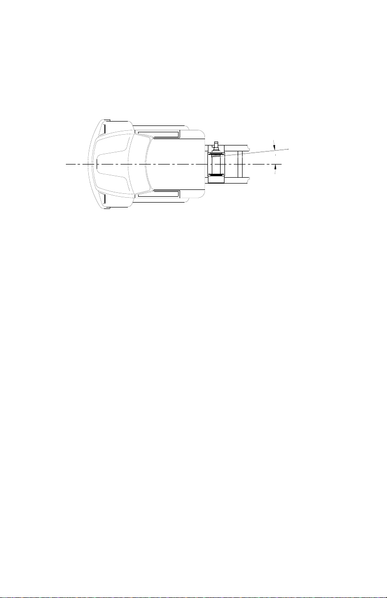
To install the u-bolt clamp style of anchor, first prepare the
end of the cable as recommended by the wire rope
manufacturer. Pass the wire rope through the u-bolt so
that the end extends approximately 2x the diameter of the
cable. Tighten the clamp evenly until the wire rope begins
to deform slightly under the u-bolt and the cable is held
securely.
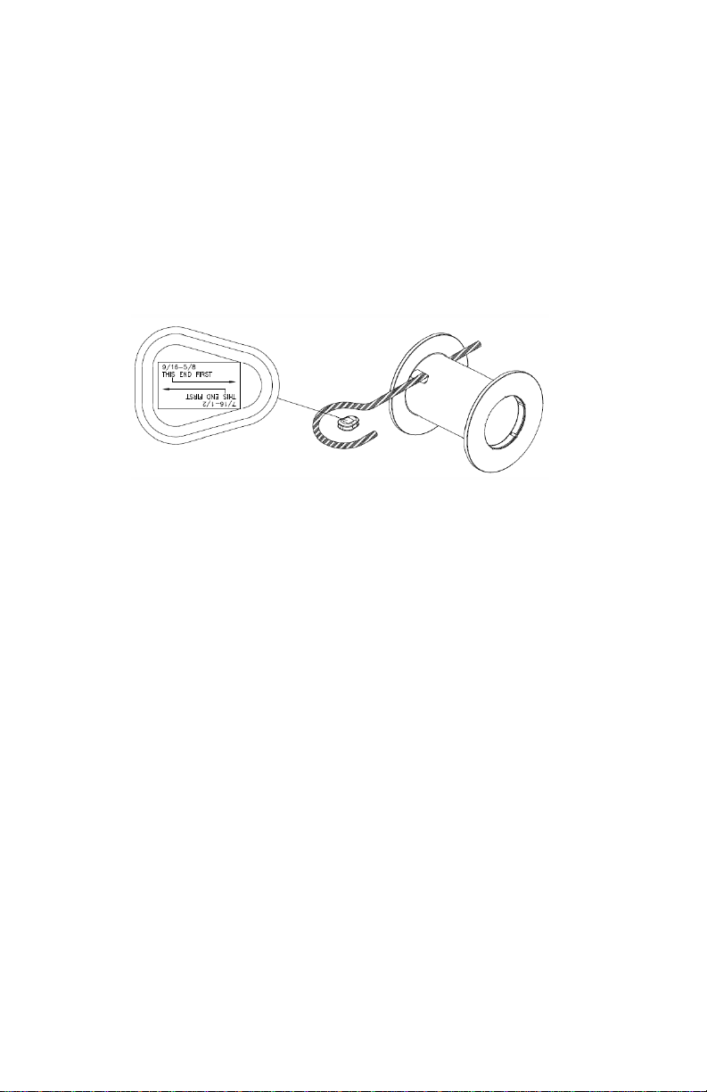
When using the ferrule wedge anchor the cable must be 6
strand. First, make sure the cable end is cut clean and
square. Insert the cable through the ferrule and spread
the strands to insert the wedge halves over the core of the
wire rope. Position individual strands into proper grooves
around the wedge halves and tap the wedges until they
are flush with the strand ends. Slide the ferrule back over
the wedge and drive the wedge into the ferrule with a
hammer and short pipe which fits inside the strands and
over the core.
WARNING: CABLE ANCHORS ON TULSA WINCHES
ARE NOT DESIGNED TO HOLD THE RATED LOAD OF
THE WINCH. YOU MUST KEEP AT LEAST 5 WRAPS
OF CABLE ON THE DRUM TO INSURE THAT THE
CABLE DOES NOT COME LOOSE.

9
Sel-0010.docx
Rev2
WINCH MOUNTING
You must make sure that your winch is securely mounted
in order for it to function properly and to insure safe
operation. The mount must be flat to insure proper
alignment between the gearbox side, the drum, and the
clutch.
A rule of thumb to use when selecting capscrews to mount
the winch is to use the same size and number of
capscrews to fasten the winch to its mount as we use to
fasten the gearbox and end bracket to the winch frames.
Winches must never be fastened directly to the frame of a
truck; mounting brackets as shown below should be used.
The mounting span of the winch is very important; you
should make sure that the mounting span is as close to
the values shown in the chart below as possible.
All capscrews used to mount the winch should be Grade 8
or better and should be carefully tightened to the proper
torque value for their size. All moving parts used to drive
mechanical winches should be secure and guards used, if
they are in accessible locations. If the winch being
mounted is hydraulically driven, make sure the system is
clean and that all components function properly, especially
the relief valve.
Model No. of
Capscrews Size
Capscrews
506W
(USE MOUNTING HOLES PROVIDED IN BASE
OF WINCH)
707W
1200W
1500W
3541RL 10 3/4"
RN45P 8 7/8"
RN60P 8 7/8"
RN80P 8 7/8"
RN100P 8 1 1/8"
RN130P 8 1 1/8"

10
Sel-0010.docx
Rev2
WINCH MAINTENANCE
A winch, like any other type of machinery, needs periodic
maintenance and inspection to maintain its performance
capabilities, give lasting value, and insure safe mechanical
workings. Good maintenance consists of three steps.
1. A daily inspection to insure that there are no oil
leaks present, that all mounting bolts and other
fasteners are tight, and that wire rope is in good
condition
2. Periodic servicing of the winch includes changing
the oil in both the gearbox and the brake section.
Severity of use will determine the need for oil
changes but it should be checked at a minimum
of every 500 operating hours and changed every
1000 hours of operation. Factors such as
extremely dirty conditions or widely varying
temperature changes may dictate even more
frequent servicing.
3. Complete teardowns and component inspections.
Again, severity and frequency of use will
determine how often this should be done. If the
equipment on which this winch is mounted is
subject to inspection standards, then those
standards must also apply to the winch and be
followed. If oil changes reveal significant metallic
particles, then a teardown and inspection must
be made to determine the source of wear.

11
Sel-0010.docx
Rev2
LUBRICATION
1. Check gearbox oil levels weekly. If the oil level
does not show a satisfactory amount, refill oil
according to the individual winch manual.
2. Check brake oil level and fill or replace if oil
shows significant metallic particles.
3. Lube all bushings equipped with grease zerks
with a good quality lithium based chassis lube.
4. Lubricate the cable based on your wire rope
supplier’s recommendations.
Tulsa planetary winches are shipped from factory with
SAE 90 EP gear lube in the gearbox and SAE 20-20W
motor oil in the brake section. This oil should be
satisfactory for operation in ambient temperatures from -
10° F to +110° F. If your work calls for operation in
temperatures outside this range, contact Tulsa Winch for
recommendations

12
Sel-0010.docx
Rev2
HYDRAULIC SYSTEM
The hydraulic system driving the winch should use only
high quality hydraulic oils from reputable suppliers. These
oils should contain additives to prevent foaming and
oxidation in the system. All winch hydraulic systems
should be equipped with a return line filter capable of
filtering 10-micron particles from the system
HYDRAULIC SCHEMATIC
AIR SCHEMATIC

13
Sel-0010.docx
Rev2
BRAKE SYSTEM
The winch braking system is a multiple disc, spring applied
hydraulically released setup that is activated via the port in
the brake housing. During pay-in the brake is not released
but bypassed through the one-way cam clutch. When the
load comes to a stop, the cam clutch locks up and the load
is prevented from slipping by the brake.
During payout, a brake valve is used to prevent the load
from moving faster that desired. This valve partially blocks
the main line from the motor back to the directional control
valve, allowing only a limited amount of oil through the
motor.

14
Sel-0010.docx
Rev2
DRUM CLUTCH POSITION INDICATOR
The clutch position indicator (shown above) operates in a
normally open position. When properly installed, as
pictured in the circuit below in addition to the intelliguard II
system, a warning light or horn will indicate when the drum
clutch is disengaged.
Note: the ground wire must be connected to the same
terminal as the black wire running from the intelliguard II
unit to the switch
GROUND POWER

15
Sel-0010.docx
Rev2
ELECTRIC 2-SPEED SHIFT

16
Sel-0010.docx
Rev2
INTELLIGUARD
The torque induced within the winch drive train is
measured by a torque sensing unit and relayed to the
capacity indicator & the data logger as a ‘percentage of
allowed torque’. The data logger will only record torque
instances that are greater than 80% of the rated torque
capacity of the winch. System events such as power on,
power off, clutch disengage and clutch engage are also
recorded.
Installation Steps
1. Ensure you have the data logger, wiring harness and
capacity indicator that was calibrated from the factory
for the winch you are installing.
2. Recognize the length of the cable to connect to the
winch from the data logger and mount the data logger
in the cab accordingly.
3. Mount the capacity indicator inside the cab located as
to be visible by the operator when operating the
winch. Keep in mind the length of the cable when
locating the capacity indicator.
4. Route and connect the torque sensor wire from the
data logger to the winch being sure not to coil the
wire.
5. Connect the two ringed terminals to the clutch
position indicator on the winch.
6. Connect the power leads (red +) (black -) to a power
source such that the intelliguard system is powered
when the PTO is energized or the ignition switch is in
the on position. Note: the time at which the
Intelliguard unit is powered on and off is logged and
reported on the data log file and the summary report.
Connects to clutch
position indicato
r
(Winch)
Connects to
torque senso
r
(Winch)
Power supply connects to
vehicle ignition system
(12 v)
Capacity
Indicator Data Logger

17
Sel-0010.docx
Rev2
1. Ensure that the data logger, wiring harness, &
capacity indicator are kept with winch. The parts are
calibrated from the factory for a particular winch and
cannot be mixed without re-calibration.
2. Do not use magnets on or around winches with
Intelliguard.
3. Before any welding is done disconnect the data
logger, capacity indicator and torque sensor.
4. When installing Intelliguard the power supply must be
the last thing to connect. Otherwise the system will
invoke an error code indicating one of the
components is malfunctioning or is disconnected.
5. After the system is fully installed and powered up
check to ensure there are no flashing lights on the
capacity indicator or brain box. If there are flashing
lights contact Tulsa Winch service dep’t for guidance.

18
Sel-0010.docx
Rev2
CAPACITY INDICATOR REALTIME DISPLAY
The Capacity Indicator displays the measured torque
value using five LED’s as follows.
Table 1 Capacity Indicator Realtime LED Display
Torque Load (% of rated
capacity)
Capacity Indicator LED Display
0 ≤Torque ≤70%
Power/Status % Torque (see above)
71% < Torque ≤80%
81% < Torque ≤90%
91% < Torque ≤100%
101% < Torque ≤110%
111% < Torque ≤125%
The Capacity Indicator displays its status using the Power
LED, which is a dual-color type. The Power LED will
appear as a static color (red, green, orange) for normal
operation, or will flash when an error occurs in
downloading via the USB connection.
Table 2 Capacity Indicator Status Display
Status LED Display
Power On
System Initialization Power/Status % Torque (see above)
Power On
No Torque
Recorded
Power On
Torque
Records Available
Power On
System Error
On USB (Flashing)
Power Off

E
r
Sel-0010.docx
Rev2
The Capacity
might occur.
W
the Capacity I
n
and the Datal
o
with a corresp
o
Table 3 Cap
a
r
ror Event
Value
167 Real
T
168 Real
169 Inval
170 In
t
172 Loss
B
e
Indic
a
173 Ca
p
Resp
o
Indicator also dis
W
hen a system e
r
n
dicator will start fl
o
gger will log the
o
nding error event
v
a
city Indicator Error
Values
Error
T
ime Clock Stopp
e
Time Clock Batter
y
Low
id Real Time Cloc
k
Value
t
ernal Datalogger
Memory Error
of Communication
s
e
tween Capacity
a
tor and Datalogg
e
p
acity Indicator not
o
nsive to Datalogg
e
Commands
Capacity In
d
plays system err
o
r
ror occurs, the L
E
ashing (see chart
b
errors that it can
v
alue.
Display and Error
Flashing L
E
e
d
Power/Status
y
k
s
e
r
e
r
d
icator
19
o
rs that
E
D’s on
b
elow),
detect
Event
E
D Display
Error Code

20
Sel-0010.docx
Rev2
WINCH MODEL CODES
(after 01-01-03)
RN100 P H L X O A 1
Basic Model
Gear Type
W=Worm
P=Planetary
Drive Type
H=Hydraulic
M=Mechanical
Gearbox Position
(viewed from rear of truck)
L=Left
R=Right
Input Shaft Location
(viewed from rear of truck)
F=Front
R=Rear
X=Does not apply
Cable Spooling
(viewed from rear of truck)
O=Over Drum
U=Under Drum
Clutch Device
M=Mechanical
A=Air
Motor Type
1. Single Speed Gear Motor
2. Two Speed Gear Motor
3. Single Seed Geroler
4. Two Speed Geroler
5. Piston
6. Vane
X. No Motor
Other manuals for Rufnek Intelliguard 506W
1
This manual suits for next models
12
Table of contents
Other Tulsa Winch manuals

Tulsa
Tulsa Rufnek Intelliguard 45 User manual

Tulsa
Tulsa RUFNEK 15 User manual

Tulsa
Tulsa RUFNEK 10 User manual

Tulsa
Tulsa 354IRL User manual

Tulsa
Tulsa RUFNEK 30 User manual

Tulsa
Tulsa 354IRL User manual

Tulsa
Tulsa Rufnek Intelliguard 3541RL User manual

Tulsa
Tulsa Rufnek Intelliguard 506W Operating instructions

Tulsa
Tulsa RUFNEK 130 User manual

Tulsa
Tulsa RUFNEK 20 User manual