Allgemeine Installations-Hinweise
1. Diese Leuchte ist nach geltenden europäischen
Vorschriften (EN 60598) gebaut und geprüft.
2. Bei unsachgemässer Montage oder Gebrauch
wird keine Haftung übernommen.
3. Nur für Verwendung in trockenen Räumen.
Informations générales pour l’installation
1. Ce luminaire est fabriqué et examiné selon les
normes européennes (EN 60598).
2. Nous déclinons toute responsabilité en cas de
non respect des instructions de montage et
d’utilisation.
3. Uniquement pour usage dans locaux secs.
General installation instructions
1. This luminaire has been designed and checked
to comply with the European regulations (EN
60598).
2. We exclude liability for improper mounting or
use.
3. To use in dry rooms only.
Nummer - Numéro - Number
Datum - Date
Änderungen - Modications
Seite - Page
Montageanleitung - Instruction de montage - Mounting instruction
Technische Änderungen vorbehalten
Modications techniques sous réserve
Technical modications excepted
M0069dfe
29.06.2005
26.08.2015
2/2
TULUX AG Tuggen Tel +41 (0)55 465 60 00 / Fax +41 (0)55 465 60 01 Cortaillod Tel +41 (0)32 843 03 03 / Fax +41 (0)32 843 03 09 www.tulux.ch
Montage-Hinweise
1. Elektroinstallationen und Reparaturen müssen
von einer Fachperson ausgeführt werden.
2. Der Netzanschluss muss bei Installationsbeginn
spannungsfrei sein.
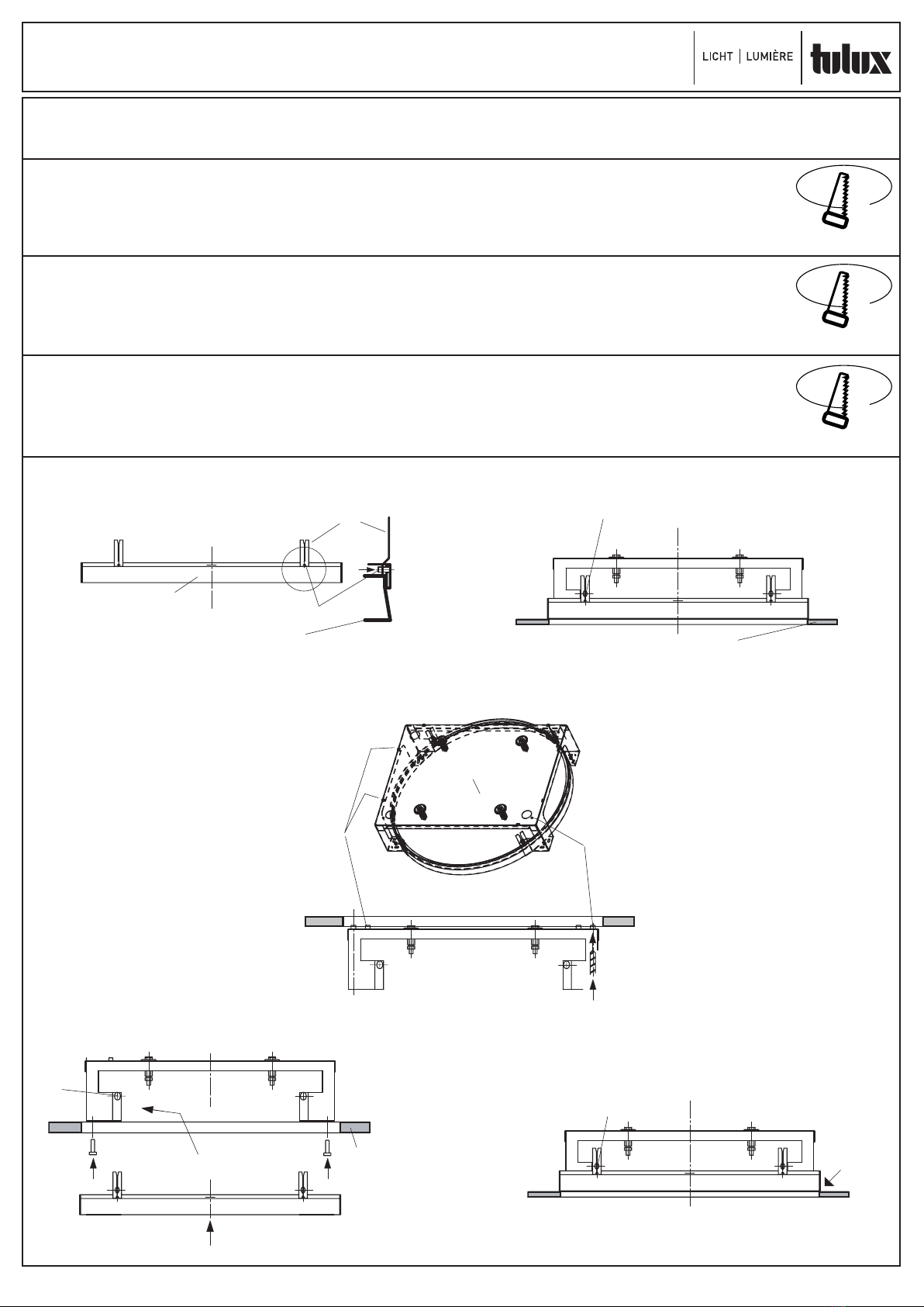
Für Metalldecken
3. Ausschnitt (Ø 555 ±1 mm) in Blechpanele
schneiden. Dünne Blechpanelen müssen
bauseitig im Randbereich verstärkt werden!
4. Nivellierbügel (a1) mittels Gewindestifte mit
Putzring zusammenschrauben (a) (innerhalb
Putzring).
5. Putzring mit Nivellierbügel in Montagebügel
einführen und mit Kordelschrauben (b) xieren.
(Unterkant bündig).
6. Montagebügel kompl. auf Blechpanele bauseitig
befestigen (Kleben od. mit bauseitiger Konstruk-
tion).
Für verputzte Hohldecken,
Deckenstärke bis 30 mm.
3. Ausschnitt (Ø 560 ±1 mm) in Hohldecke
vorbereiten. Montagebügel auf Deckenausspa-
rung halten, über Positionierungs-Haken (c) in
Ausschnitt zentrieren (Im Raum ausrichten!).
4. Löcher (d) als Bohrschablone verwenden.
5. Montagebügel in Decken-Ausschnitt einfahren
und mit Schrauben (f) xieren. (Schrauben nicht
im Lieferumfang enthalten!).
6. Nivellierbügel mittels Gewindestifte mit Putzring
zusammenschrauben (a) (innerhalb Putzring).
7. Putzring mit Nivellierbügel in Montagebügel
einführen (g), gewünschtes Verputzniveau
einstellen und mit Kordelschrauben (i) xieren.
8. Decke verputzen. Um Rissbildungen zu ver-
meiden empfehlen wir Putzring und Putz durch
einen Schwedenschnitt zu trennen.
Für Decken mit fertiger Oberäche, Deckenstär-
ke bis 30 mm, Schnittkante sichtbar.
3. Ausschnitt (Ø 555 ±1 mm) in Decke vorbereiten.
4a. Vorgängige Montage:
Nivellierbügel mittels Gewindestifte mit Putzring
zusammenschrauben (a) (innerhalb Putzring).
5a. Putzring mit Nivellierbügel in Montagebügel
einführen und mit Kordelschrauben (b) xieren.
(Unterkant bündig).
6a. Montagebügel im Raum ausrichten und auf
Decke montieren (Langlöcher im Bügel verwen-
den, Löcher in Decke nicht durchbohren).
4b. Nachträgliche Montage:
Montagebügel in Deckenöffnung schräg durch
Ausschnitt einfahren, im Raum ausrichten und
bauseitig befestigen (kleben, schrauben) (h).
5b. Kordelschrauben von Montagebügel entfernen
(i).
6b. Nivellierbügel mittels Gewindestifte mit Putzring
zusammenschrauben (a) (innerhalb Putzring).
7b. Putzring in gespanntem Zustand durch Decken-
ausschnitt, schräg (e) in seitliche Aussparung (k)
von Metallbügel einführen.
8b. Putzring auf Decke senken und mittels Nivel-
lierbügel auf Montagebügel ausrichten und mit
Kordelschrauben befestigen.
Consignes de montage
1. L’installation électrique et les réparations doivent
être conduites par une personne qualiée.
2. Au début de l’installation, l’alimentation doit être
coupée.
Pour les plafonds en métal
3. Éffectuer une coupe de (Ø 555 ±1 mm) dans
les panneaux. Les panneaux d’une épaisseur
plus ne dans la zone extérieure doivent être
renforcés par le maître d’ouvrage!
4. Les brides de nivellement doivent être vissées à
l’aide d’une vis sans tête à la bague d’enduit (a)
(sur la bague d’enduit).
5. Installer la bague d’enduit et les brides de nivel-
lement dans les brides de montage et les xer
à l’aide de vis à molette (b). (au bord de l’arête
inferieure).
6. Le maître d’ouvrage doit xer les brides de mon-
tage sur les panneaux (souder ou xer, selon le
maître d’ouvrage).
Pour les plafonds avec un enduit, avec une
épaisseur pouvant aller jusqu’à 30 mm.
3. Faire une découpe dans le plafond creux (Ø
560 ±1 mm). Placer les brides de montage sur
l’évidement du plafond et les centrer au niveau
des coins de la découpe (c) (ajuster en fonction
de l’espace!).
4. Utiliser les perforations (d) comme des gabarits
de perçage.
5. Installer les brides de montage dans la découpe
du plafond et les xer avec des vis (f). (vis non
comprises dans le matériel livré!).
6. Fixer les brides de nivellement à la bague
d’enduit à l’aide de vis sans tête (a) (sur la
bague d’enduit).
7. Insérer la bague d’enduit et les brides de nivel-
lement dans les brides de montage (g), doser
l’application d’enduit souhaitée et xer à l’aide
de vis à molette (i).
8. Énduire le plafond. Pour la formation de cra-
quelures, nous conseillons de séparer la bague
d’enduit et l’enduit grâce à l’utilisation d’une
coupe suédoise.
Pour les plafonds avec une surface nie, d’une
épaisseur pouvant aller jusqu’à 30 mm, arrête de
coupe visible.
3. Faire une découpe (Ø 555 ±1 mm) dans le
plafond.
4a. Montage préalable:
Fixer les brides de nivellement avec la bague
d’enduit à l’aide de vis sans tête (a) (sur la
bague d’enduit).
5a. Installer la bague d’enduit et les brides de nivel-
lement dans les brides de montage et les xer
à l’aide de vis à molette (b). (au bord de l’arête
inferieure).
6a. Ajuster les brides de montage dans l’espace
et les installer sur le plafond (utiliser les trous
oblongs dans la bride, ne pas percer le plafond).
4b. Montage ultérieur:
Insérer les brides de montage dans le trou du
plafond de biais par la découpe, les ajuster dans
l’espace et xer (coller, visser) (h).
5b. Retirer les vis à mollette des brides de montage
(i).
6b. Fixer les brides de nivellement à la bague
d’enduit à l’aide de vis sans tête (a) (sur la
bague d’enduit).
7b. Insérer la bague d’enduit à l’état mou par la
découpe du plafond, de biais dans l’évidement
latéral (e) de la bride en métal (k).
8b. Abaisser la bague d’enduit sur le plafond et à
l’aide d’une bride de nivellement, la connecter à
la bride de montage et la xer à l’aide de vis à
mollette.
Mounting notes
1. Electrical installations and repairs must be
performed by an electrician.
2. The power supply must be turned off at the
beginning of installation.
For metal ceilings
3. Cut an opening (Ø 555 ±1 mm) in the metal
panels. Thin metal panels must be reinforced at
the edges on site!
4. Screw the levelling bracket (a1) to the plaster
ring using grub screws (a) (inside the plastering
ring).
5. Insert the plaster ring with levelling bracket into
the mounting bracket and x with knurled thumb
screws (b). (lower edge ush).
6. Fix the mounting bracket fully to the metal pa-
nels on site (using adhesive or on site construc-
tion).
For rendered hollow ceilings, ceiling thickness
up to 30 mm.
3. Prepare an opening (Ø 560 ±1 mm) in the
hollow ceiling. Hold the mounting bracket to
the ceiling opening, centre in the opening over
positioning hooks (c) (align within the room!).
4. Use holes (d) as the drilling template.
5. Insert the mounting bracket into the ceiling
opening and x with screw (f). (Screws not
supplied!).
6. Screw the levelling bracket (a1) to the plaster
ring using grub screws (a) (inside the plastering
ring).
7. Insert the plaster ring with levelling bracket into
the mounting bracket (g), set to the desired ren-
dering level and x with knurled thumb screws
(i).
8. Render the ceiling. To avoid cracks forming
we recommend separating the plaster ring and
rendering using a trowel groove.
For ceilings with nished surface, ceiling thick-
ness up to 30 mm, visible cutting edge.
3. Prepare an opening (Ø 555 ±1 mm) in the cei-
ling.
4a. Mounting in advance:
Screw the levelling bracket (a1) to the plaster
ring using grub screws (a) (inside the plastering
ring).
5a. Insert the plaster ring with levelling bracket into
the mounting bracket and x with knurled thumb
screws (b). (lower edge ush).
6a. Align the mounting bracket within the room and
mount on the ceiling (Use the slotted holes in
the bracket, do not drill holes into the ceiling).
4b. Mounting afterwards:
Insert the mounting brackets into the ceiling at
an angle through the opening, align within the
room and x on site (using adhesive or screws)
(h).
5b. Remove knurled thumb screws from mounting
bracket (i).
6b. Screw the levelling bracket (a1) to the plaster
ring using grub screws (a) (inside the plastering
ring).
7b. Insert the plaster ring through the ceiling open-
ing under tension, then insert it into the side
opening (k) of the metal bracket at an angle (e).
8b. Lower the plaster ring onto the ceiling and align
it to the mounting bracket using a levelling bra-
cket and x with knurled thumb screws.