Turbo Energy Lithium Series User manual

www.turbo-e.com
1. Inverter configuration
1.1. Connect Inverter to Wifi
To be able to upload the SunBox to the cloud and be able to see the monitoring of the system, it is essential
to connect the equipment to the internet. To do this, the following steps must be followed:
Step 0: Locate the serial number of the logger.
At the bottom of the inverter there is a label with a QR code, the serial number of your logger and the
password to access the Wi-Fi of the logger.
The logger creates a Wi-Fi network whose name is "AP_" followed by the serial number of the logger.
Step 1: Connect to the Wi-Fi network.
With an electronic device that has Wi-Fi (PC, Tablet, Smartphone ...) the connection with the Wi-Fi of the
recorder is established:
Open the wireless network connection of your PC, tablet, or smartphone.
Click View Available Wireless Networks
Select the corresponding one with the device which you want to connect with (identified by "AP_" and the
serial number of logger)
Enter the key that appears on the logger along with the serial number.
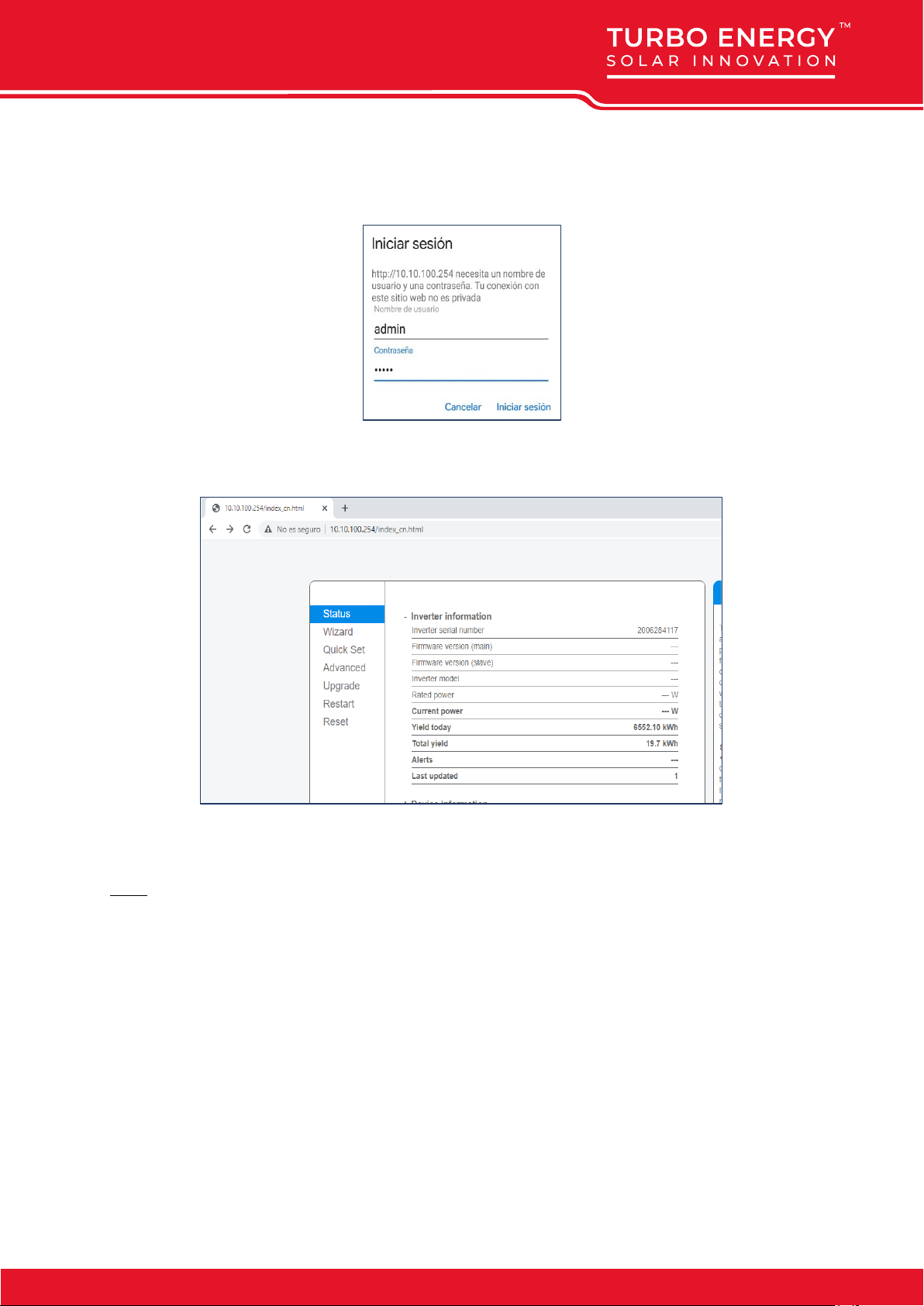
Step 2: Connect to the web portal.
Once connected to the Wi-Fi network with your PC, tablet, or smartphone you must access the web portal
of the register.
To do this, a web browser on the PC, tablet or smartphone that has been connected to the wi-Fi of the
logger.

www.turbo-e.com
Type in the address bar of the web browser the text "10.10.100.254"
A login pop-up window will appear asking for username and password. The default user is "admin" and
the password is "admin" and pulsar the button "Login".
Once you have accessed the web portal of the registrar you will be able to see the "Status" page with
general information of the registrar.
Click on the "Wizard" link under the "Status" link to run the connection wizard from the logger to the wi-fi
of the installation (the Wi-Fi of your house or your plant).
Step3: Configure the LOGGER's access to the wi-fi of the plant.
Select the wi-fi of the plant.
When we run the connection wizard, we see the list of Wi-Fi networks to which the registrar has access.
Among them must appear the Wi-Fi of our plant. We must select that Wi-Fi and press the "Next" button at
the bottom of the screen:

www.turbo-e.com
Step 3.2: Enter the password of the Wi-Fi of the plant: in the field "Password" enter the password of the
Wi-Fi of your plant and press the button "Next·"
Step 3.3: In this step it is NOT necessary to select any option and then press the "Next" button. Used to
configure the security of the connection a la Wi-Fi. Selecting Hide AP, the Wi-Fi network will appear as
hidden.
Step 3.4 If the adjustment has been made successfully press the "OK" button to restart the connection.

www.turbo-e.com
If the restart occurs successfully a message will appear indicating that it has been done successfully, if it
does not appear then refresh the browser page:
Step 4: Check the connection of the REGISTRAR to the wi-Fi of the plant.
After restarting the web page log back in to the "Status" page and check the status of the registrar's
network connection:

www.turbo-e.com
Once we have verified that the registrar is connected to the Wi-Fi of the plant and (which must have
internet access) it is possible to add the plant to the cloud platform.
1.2. Inverter settings
When programming the inverter, you can choose between several configuration options:
1. Selling first: the priority for excess energy is to deliver it to the grid.
2. Zero Export to Load: The output power feeds the Load.
3. Zero export to CT: Production feeds the sum of loads (Network and Load).
Select one of these three modes and enable or disable the option to pour power into the grid.
In addition, power can be prioritized to the charge or to the battery.
The recommended working mode is: Zero Export to CT / Solar Sell activated / Load First. In this way the
energy generated will feed the load, the excess amount will go to the battery and finally, the excess energy
will be poured into the grid.
The inverter also incorporates the possibility of using the Grid Peak Shaving function, which allows to
reduce the maximum power consumed from the network. With this function the user can have less power
contract in the hours of the day that are more expensive and the surplus power that is consumed, will be
supplied by the battery.
There are three different modes:
- GM (General Mode): Mode to supply the energy consumed with Battery and plates
- BU (BackUP): No battery discharge mode
- CH (Charge):Battery charging mode
- Selling first: Entregar a la red primero
- Zero Export to Load: La potencia de salida se ajusta a la carga
de BackUp
- Zero Export to CT: El sistema ajusta la producción a la suma
de las cargas (Red y BackUp)
- Solar Sell: Vender el excedente de energía
- Max Sell Power: máxima Potencia de salida
- Zero-export Power: Potencia de salida de la red
- Batt First: La energía de las placas se utiliza para cargar las
baterías primero.
- Load First: La energía de las placas se utiliza para la carga y
después para las baterías.
- Grid Peak Shaving: Limite de potencia a tomar de red
8000W.

www.turbo-e.com
2. Battery configuration
Each module has 4 DIP (Dual Inline Package) switches that will be configured differently depending on the
number of batteries to be connected.
They are configured according to the binary code, starting with the master.
Address
Dial switch position
Explain
Dips
#1
#2
#3
#4
1
ON
OFF
OFF
OFF
Pack1/Master
2
OFF
ON
OFF
OFF
Pack2
3
ON
ON
OFF
OFF
Pack3
4
OFF
OFF
ON
OFF
Pack4
5
ON
OFF
ON
OFF
Pack5
6
OFF
ON
ON
OFF
Pack6
7
ON
ON
ON
OFF
Pack7
8
OFF
OFF
OFF
ON
Pack8
9
ON
OFF
OFF
ON
Pack9
10
OFF
ON
OFF
ON
Pack10
11
ON
ON
OFF
ON
Pack11
12
OFF
OFF
ON
ON
Pack12
13
ON
OFF
ON
ON
Pack13
14
OFF
ON
ON
ON
Pack14
15
ON
ON
ON
ON
Pack15
Any changes to the DIPs must be made with the battery turned off.
When the battery works by voltage, it is not necessary to communicate the batteries with each other or
select a certain DIP configuration.
1=ON
0=OFF
1
3
2
4

www.turbo-e.com
3. WIRING Configuration
The cable needed to make the connection is the RJ45. It is a special cable that is
composed of 8 smaller cables each with a different color configuration.
It’s needed to use a standard pin-to-pin cable with RJ45 connector.
CAUTION: READ THE INSTRUCTION AND INSTALLATION MANUAL BEFORE USING THE PRODUCT
©Copyright 2020. All rights reserved.
The specifications of the data sheet can be changed without prior notice.
For the connection between the
inverter and battery, the RJ45 cable
will be connected to the CAN-1 port in
the battery.
In the inverter, the
RJ45 cable will be
connected to the
BMS CAN port.
Other manuals for Lithium Series
8
This manual suits for next models
3
Table of contents