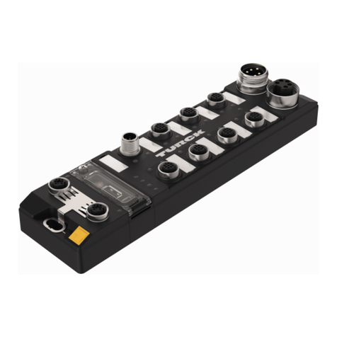
turck TBEN-L Series User manual

Your Global Automation Partner
Instructions for Use
TBEN-L…-PLC-…
Compact
CODESYS V3 PLC

2Hans Turck GmbH & Co. KG | T +49 208 4952-0 | F +49 208 4952-264 | [email protected] | www.turck.com

V02.00 | 2019/11 3
Table of Contents
1 About these Instructions................................................................................................................... 7
1.1 Target groups................................................................................................................... 7
1.2 Explanation of symbols used ........................................................................................ 7
1.3 Other documents ............................................................................................................ 7
1.4 Feedback about these instructions.............................................................................. 7
2 Notes on the Product.........................................................................................................................8
2.1 Product identification..................................................................................................... 8
2.2 Scope of delivery ............................................................................................................. 8
2.3 Legal requirements......................................................................................................... 8
2.4 Manufacturer and service.............................................................................................. 8
3 For Your Safety.................................................................................................................................... 9
3.1 Intended use..................................................................................................................... 9
3.2 General safety notes ....................................................................................................... 9
4 Product Description .........................................................................................................................10
4.1 Device overview ............................................................................................................10
4.1.1 Block diagram..................................................................................................................................11
4.1.2 Display Elements............................................................................................................................12
4.2 Properties and Features...............................................................................................12
4.3 Operating principle.......................................................................................................13
4.4 Functions and operating modes ................................................................................13
4.4.1 Switch Mode....................................................................................................................................13
4.4.2 Dual MAC Mode (firmware version higher than V1.4.6.0)...............................................13
4.4.3 Master/slave operation modes .................................................................................................13
4.4.4 COM interfaces................................................................................................................................15
4.4.5 CAN interfaces.................................................................................................................................15
4.4.6 Web server........................................................................................................................................16
4.5 Technical accessories....................................................................................................16
5 Mounting............................................................................................................................................17
5.1 Mounting the device outdoors...................................................................................17
5.2 Grounding the device...................................................................................................18
5.2.1 Equivalent wiring diagram and shielding concept ...........................................................18
5.2.2 Shielding of the fieldbus and I/O level...................................................................................19
5.2.3 Grounding the device – I/O level and fieldbus level.........................................................19
6 Connecting ........................................................................................................................................21
6.1 Connecting the modules to Ethernet ........................................................................21
6.2 Connecting the power supply ....................................................................................21
6.3 Connecting serial devices (COM0 and COM1) .........................................................23
6.4 Connecting CAN devices (CANout and CANin)........................................................23
6.5 Connecting digital sensors and actuators................................................................24
6.6 Using the USB device port ...........................................................................................24
6.7 USB host port .................................................................................................................24
7 Commissioning .................................................................................................................................25
7.1 Setting the Ethernet port mode (firmware version V1.4.6.0 or higher)..............25
7.1.1 Setting the Switch Mode.............................................................................................................25

Table of Contents
4Hans Turck GmbH & Co. KG | T +49 208 4952-0 | F +49 208 4952-264 | [email protected] | www.turck.com
7.1.2 Setting the Dual MAC Mode ......................................................................................................26
7.2 Setting the IP address...................................................................................................26
7.2.1 Setting the IP address via switches at the device...............................................................26
7.2.2 Setting the IP address with Turck Service Tool ...................................................................28
7.2.3 Setting the IP address via the web server .............................................................................29
7.3 Put master/slave functions into operation in CODESYS........................................31
7.3.1 Installing the devices package..................................................................................................31
7.3.2 Creating a standard project with TBEN-L…-PLC… ...........................................................32
7.3.3 Configuring the Network ............................................................................................................33
7.3.4 Configuring the Ethernet interfaces .......................................................................................35
7.3.5 Commissioning TBEN-L...-PLC-... as Modbus TCP Master ................................................37
7.3.6 Commissioning TBEN-L...-PLC-... as Modbus TCP Slave....................................................41
7.3.7 Commissioning TBEN-L...-PLC-... as Modbus RTU Master................................................42
7.3.8 Commissioning TBEN-L...-PLC-... as Modbus RTU Device ................................................45
7.3.9 Commissioning TBEN-L...-PLC-... as PROFINET Controller ...............................................47
7.3.10 Commissioning TBEN-L...-PLC-... as PROFINET Device......................................................50
7.3.11 Commissioning TBEN-L...-PLC-... in parallel as PROFINET controller and device ....54
7.3.12 Commissioning TBEN-L...-PLC-... as EtherNet/IP™ Scanner.............................................56
7.3.13 Commissioning TBEN-L...-PLC-... as EtherNet/IP™ Slave (Device) .................................58
7.3.14 Commissioning TBEN-L...-PLC-... parallel as EtherNet/IP™ Scanner and Slave
(Device)..............................................................................................................................................64
7.3.15 Commissioning TBEN-L...-PLC-... as CANopen Manager ..................................................65
7.3.16 Commissioning TBEN-L...-PLC-... as CANopen Device ......................................................67
7.3.17 Commissioning TBEN-L...-PLC-... as SAE J1939 Manager .................................................70
7.3.18 Displaying task and processor information..........................................................................72
7.4 Commissioning TBEN-L…PLC-… as Cloud gateway .............................................77
7.4.1 Register or login user and project in the cloud...................................................................78
7.4.2 Creating a Cloud project .............................................................................................................79
7.4.3 Activate a device as Cloud gateway in Turck Cloud Portal.............................................82
7.4.4 Configuring the Cloud access in the web server................................................................85
7.4.5 Transfer process data from CODESYS to the cloud ...........................................................86
7.4.6 Setup firewall for Ethernet port P2..........................................................................................88
8 Parameterizing and Configuring...................................................................................................89
8.1 Parameters......................................................................................................................89
8.1.1 General PLC parameters..............................................................................................................90
8.1.2 Parameters of the local DXP channels (Local I/O) ..............................................................93
8.1.3 Parameter VAUX Control.............................................................................................................93
8.1.4 Interface parameters – COM0/COM1 .....................................................................................93
8.1.5 Interface parameters – CAN .......................................................................................................94
8.1.6 Parameterizing and configuring the device via the web server...................................95
8.2 Configuring the real-time clock (RTC) .......................................................................98
8.2.1 Setting the RTC with Turck Service Tool................................................................................98
8.2.2 Setting the RTC via the web server..........................................................................................99
8.2.3 Setting the RTC via CODESYS ................................................................................................. 101
9 Operating .........................................................................................................................................102
9.1 LED displays................................................................................................................. 102
9.2 Software diagnostic messages ................................................................................ 104
9.2.1 Diagnostics.................................................................................................................................... 104
9.2.2 Module status............................................................................................................................... 106
9.3 Using the USB host port ............................................................................................ 108
9.3.1 USB host port – function overview....................................................................................... 108
9.3.2 Executing USB functions .......................................................................................................... 111
9.3.3 USB functions – behavior of the RUN-LED in case of an error .................................... 113

V02.00 | 2019/11 5
9.4 Operating the device with the web server ............................................................ 113
9.4.1 Changing the web server password .................................................................................... 113
9.4.2 Manage data node points from CODESYS symbol table.............................................. 114
10 Troubleshooting .............................................................................................................................116
11 Maintenance....................................................................................................................................117
11.1 Executing the firmware update............................................................................... 117
11.1.1 Executing the firmware update via USB storage medium........................................... 117
11.1.2 Carry out firmware update via FDT/DTM ........................................................................... 117
11.1.3 Executing the firmware update via the web server ....................................................... 121
12 Repair................................................................................................................................................121
12.1 Returning devices....................................................................................................... 121
13 Technical data .................................................................................................................................122

Table of Contents
6Hans Turck GmbH & Co. KG | T +49 208 4952-0 | F +49 208 4952-264 | [email protected] | www.turck.com

V02.00 | 2019/11 7
1 About these Instructions
These operating instructions describe the structure, functions and the use of the product and
will help you to operate the product as intended. Read these instructions carefully before using
the product. This is to avoid possible damage to persons, property or the device. Retain the in-
structions for future use during the service life of the product. If the product is passed on, pass
on these instructions as well.
1.1 Target groups
These instructions are aimed a qualified personal and must be carefully read by anyone
mounting, commissioning, operating, maintaining, dismantling or disposing of the device.
1.2 Explanation of symbols used
The following symbols are used in these instructions:
DANGER
DANGER indicates a dangerous situation with high risk of death or severe injury if
not avoided.
WARNING
WARNING indicates a dangerous situation with medium risk of death or severe in-
jury if not avoided.
CAUTION
CAUTION indicates a dangerous situation of medium risk which may result in minor
or moderate injury if not avoided.
NOTICE
NOTICE indicates a situation which may lead to property damage if not avoided.
NOTE
NOTE indicates tips, recommendations and useful information on specific actions
and facts. The notes simplify your work and help you to avoid additional work.
uCALL TO ACTION
This symbol denotes actions that the user must carry out.
aRESULTS OF ACTION
This symbol denotes relevant results of actions.
1.3 Other documents
Besides this document the following material can be found on the Internet at www.turck.com:
nData sheet
nOperating instructions
nEU Declaration of Conformity
nApprovals
1.4 Feedback about these instructions
We make every effort to ensure that these instructions are as informative and as clear as pos-
sible. If you have any suggestions for improving the design or if some information is missing in
the document, please send your suggestions to [email protected].

Notes on the Product
Manufacturer and service
8Hans Turck GmbH & Co. KG | T +49 208 4952-0 | F +49 208 4952-264 | [email protected] | www.turck.com
2 Notes on the Product
2.1 Product identification
These instructions apply to the compact CODESYS V3 programmable PLCs:
nTBEN-L4-PLC-10
nTBEN-L4-PLC-11
nTBEN-L5-PLC-10
nTBEN-L5-PLC-11
2.2 Scope of delivery
nTBEN-L…-PLC-…
nClosure caps for 7/8'' connectors
nClosure caps for M12 connectors
nLabel clips
nQuick-Start Guide
2.3 Legal requirements
The device is subject to the following EC directives:
n2014/30/EU (electromagnetic compatibility)
n2011/65/EU (RoHS Directive)
2.4 Manufacturer and service
Hans Turck GmbH & Co. KG
Witzlebenstraße 7
45472 Muelheim an der Ruhr
Germany
Turck supports you with your projects, from initial analysis to the commissioning of your applic-
ation. The Turck product database contains software tools for programming, configuration or
commissioning, data sheets and CAD files in numerous export formats. You can access the
product database at the following address: www.turck.en/products
For further inquiries in Germany contact the Sales and Service Team on:
nSales: +49 208 4952-380
nTechnology: +49 208 4952-390
Outside Germany, please contact your local Turck representative.

V02.00 | 2019/11 9
3 For Your Safety
The product is designed according to state-of-the-art technology. However, residual risks still
exist. Observe the following warnings and safety notices to prevent damage to persons and
property. Turck accepts no liability for damage caused by failure to observe these warning and
safety notices.
3.1 Intended use
These devices are designed solely for use in industrial areas.
The CODESYS V3 programmable TBEN-L…-PLC-… can be used as autonomous PLC or as de-
central PLC in a network interconnection for a fast preprocessing of signals. The devices allow
autonomous control of applications without higher-level control. The TBEN-L…-PLC-… can be
used in different Ethernet networks or fieldbus systems as Master/Controller (Modbus TCP,
Modbus RTU, PROFINET, EtherNet/IP™, CANopen, SAE J1939) or Slave/Device (Modbus TCP,
Modbus RTU, PROFINET, EtherNet/IP™, CANopen) and can communicate with bus nodes or
higher-level controllers.
The cloud functionality of the TBEN-L...-PLC-... enables the direct transfer of application data to
the Turck Cloud via CODESYS variables for the purpose of data analysis or production monitor-
ing. In Dual MAC mode, the TBEN-L...-PLC-... can be operated as a node in two different Ethernet
networks.
The devices may only be used as described in these instructions. Any other use is not in accord-
ance with the intended use. Turck accepts no liability for any resulting damage.
3.2 General safety notes
nThe device may only be assembled, installed, operated, parameterized and maintained by
professionally-trained personnel.
nThe device may only be used in accordance with applicable national and international regu-
lations, standards and laws.
nThe device only meets the EMC requirements for industrial areas and is not suitable for use
in residential areas.
nThe programmable devices can be used to control machines. Changes to system or network
settings or to the control program can lead to non-defined states of the controlled ma-
chines. Changes may only be made if the controlled machine is in a safe stop state and the
device is separated from the machine.
nChange the default password of the integrated web server after the first login. Turck recom-
mends using a secure password.

Product Description
Device overview
10 Hans Turck GmbH & Co. KG | T +49 208 4952-0 | F +49 208 4952-264 | [email protected] | www.turck.com
4 Product Description
The device is designed in a fully encapsulated housing with degree of protection IP65/IP67/
IP69K. The Ethernet ports serve as interface for programming, configuration and Ethernet/ field
bus communication. The Ethernet ports serve as interface for programming, configuration and
Ethernet/ field bus communication. Two serial interfaces COM 0 and COM 1 are available for
connecting serial RS232 or RS485 devices. CANopen or SAE J1939 devices can be connected to
the TBEN-L...-PLC-... via the two CAN interfaces CANout and CANin. To connect digital sensors
and actuators, the device has eight digital I/O channels that can be used as inputs or outputs
without configuration. The USB device port is designed as a mini USB B socket and can be used
as a service interface for the device DTMs and as a programming interface for CODESYS. The
USB host port is designed as a USB2.0-A socket and is used to connect USB memory sticks for
program backup, program recovery, firmware update and data synchronization.
4.1 Device overview
218
230.5
C4C5C6C7
6.3
38.8
60.4
C0C1C2C3
24
30.2
X2
X1
P2
P1
Fig.1: TBEN-L4 –PLC-… – dimensions
218
230.5
C4C5C6C7
6.3
38.8
60.4
C0C1C2C3
24
30.2
X2
X1
P2
P1
Fig.2: TBEN-L5 –PLC-… – dimensions

V02.00 | 2019/11 11
4.1.1 Block diagram
Rotary switches
P2P1
4
13
2
4
13
2
ETH2ETH1
Ethernet
+
4
–
2
+
5
–
1
FE
3
V1 V2 +
4
–
2
+
5
–
1
FE
3
V1 V2
X1 X2
ERR
BUS
RUN
APPL
LED5
LED4
LED6
LED7
µC
Supply
µC
TTL
V1 Diag V2 Diag
Ethernet
2 A
V1 +
V1 +
1 Shield
2 VAUX1
3 V1 –
4 CAN H
5 CAN L
1 Shield
2 VAUX1
3 V1 –
4 CAN H
5 CAN L
4A
2A
2A
CAN
V2 +
IN
OUT
1 VAUX2
4 IN/OUT
2 IN/OUT
3 V2 –
5 FE
2 A
2 A
In/Output
I/O
V2 +
TTL
CAN
LED1
LED0
1 VAUX1
4
2
3 V1 –
5 FE
COM
TTL
RS485/
RS232
RS485 = DATA B
RS232 = RXD
RS485 = DATA A
RS232 = TXD
1 VAUX1
4
2
3 V1 –
5 FE
RS485 = DATA B
RS232 = RXD
RS485 = DATA A
RS232 = TXD
C2
C3
C0
C1
C4...C7
LED3
LED2
V1 +
TTL
RS485/
RS232
NVRAM
RTC (buffered)
Memory
V1 +
USB Host
SRV
0.3 A
0.3 A
Fig.3: Block diagrams TBEN-L…- PLC-…

Product Description
Properties and Features
12 Hans Turck GmbH & Co. KG | T +49 208 4952-0 | F +49 208 4952-264 | [email protected] | www.turck.com
4.1.2 Display Elements
The device has the following LED indicators:
nPower supply
nGroup and bus errors
nStatus
nDiagnostics
4.2 Properties and Features
nIntegrated Cloud functionality (≥ V1.4.6.0): Transfer of CODESYS variables into the Cloud
nPROFINET IO and EtherNet/IP™ Device, Modbus TCP, Modbus RTU and CANopen slave
nMaster functionalities:
– Modbus TCP /Modbus RTU master
– PROFINET Controller
– EtherNet/IP™ Scanner
– CANopen Manager
– SAE J1939 Manager
nEthernet and USB programming interface
nProgrammable according to IEC 61131-3 with CODESYS V3 in:
– IL = Instruction List
– LD = Ladder Logic
– FBD = Function Block Diagram
– SFC = Sequential Function Chart
– ST = Structured Text
nIntegrated Gold CAP buffered Real Time Clock (RTC)
nUSB Device port as programming and service interface
nUSB Host port for connecting USB memory sticks for firmware-update, program backup, pro-
gram restore, data synchronization
nProtocol converter - for example from Ethernet to serial communication
n7/8"-connector for power supply
– TBEN-L4-PLC-…: 4-pole
– TBEN-L5-PLC-…: 5-pole
nTwo 4-pole M12-connectors for Ethernet
n8 digital channels configurable as PNP inputs and/or outputs (2 A)
nSeveral LEDs for status indication
nSwitch Mode (< V1.4.6.0): Integrated Ethernet switch, allows line topology
nDual MAC Mode (≥ V1.4.6.0): 2 separate Ethernet ports for connecting different Ethernet net-
works
nIntegrated Webserver
nTransmission rate 10 Mbps and 100 Mbps
nFibre-glass reinforced housing
nShock and vibration tested
nFully potted module electronics
nDegree of protection IP65/IP67/IP69K

V02.00 | 2019/11 13
4.3 Operating principle
The CODESYS-3 controller TBEN- L PLC-... can be used to control smaller or modular machines
or for signal preprocessing. The device can be used in various Ethernet networks or fieldbus
systems as master/controller (Modbus TCP, Modbus RTU, PROFINET, EtherNet/IP™, CANopen,
SAE J1939) or slave/device (Modbus TCP, Modbus RTU, PROFINET, EtherNet/IP™, CANopen) and
communicates with bus nodes or higher-level controllers. As a protocol converter between two
networks, the TBEN-L...-PLC-... can for example act as a CANopen manager of a machine module
networked with CANopen and connect it to a system that is networked with PROFINET. In DUAL
MAC mode, the controller transmits data from an internal machine network to the external
Turck Cloud Portal as a participant in two separate Ethernet networks, for example.
4.4 Functions and operating modes
4.4.1 Switch Mode
In switch mode, the two Ethernet ports of the TBEN-L...-PLC-... are treated as one autocrossing
switch with one IP address [}25].
NOTE
Devices with a firmware version lower than V1.4.6.0 can only be operated in switch
mode.
4.4.2 Dual MAC Mode (firmware version higher than V1.4.6.0)
In Dual MAC mode, the two Ethernet ports of the TBEN-L...-PLC-... are treated as separate Ether-
net ports with own MAC and IP addresses. The TBEN-L…-PLC-… can therefore be a participant
in two different Ethernet networks in dual MAC mode. The two IP addresses of the separate
Ethernet ports must be located in different subnets [}25]
Example:
Port P1 (ETH1):
nIP address: 192.168.1.xxx
nSubnet mask: 255.255.255.0
Port P2 (ETH2):
nIP address: 192.168.2.xxx
nSubnet mask: 255.255.255.0
NOTE
To use the TBEN-L...-PLC-... in separate networks with combined master/slave func-
tions (see Master/Slave [}13]), the device must be operated in dual MAC mode.
4.4.3 Master/slave operation modes
The CODESYS 3 programmable TBEN-L…-PLC-… can be used as follows:
Protocol Master/Controller/Scanner/
Manager
Slave/Device
Modbus TCP x x
Modbus RTU x x
PROFINET x x
EtherNet/IP™ x x
CANopen x x
SAE J1939 x -

Product Description
Functions and operating modes
14 Hans Turck GmbH & Co. KG | T +49 208 4952-0 | F +49 208 4952-264 | [email protected] | www.turck.com
NOTE
The functions PROFINET device and EtherNet/IP™ slave are only available at Ethernet
port P1 (in CODESYS at eth0).
Possible combinations Master/Slave
The following table is valid for combinations of one Master and one Slave.
Modbus TCP
Slave
PROFINET
Device
EtherNet/IP™
Device
Modbus RTU
Slave
CANopen
Device
Modbus TCP Master x x x x x
PROFINET Controller x x* x x x
EtherNet/IP™ Scanner x x x* x x
Modbus RTU Master x x x x* x
CANopen Manager x x x x -
SAE J1939 Manager x x x x -
* These functions cannot be used together on the same Ethernet port (Dual MAC Mode) or
COM port. Each function must be configured separately on an Ethernet or COM port.
Possible combinations Master/Master
Modbus
TCP
Master
PROFINET
Controller
EtherNet/
IP™
Scanner
Modbus
RTU
Master
CANopen
Manager
SAE J1939
Manager
Modbus TCP Master - x x x x x
PROFINET Control-
ler
x - - x x x
EtherNet/IP™ Scan-
ner
x - - x x x
Modbus RTU Master x x x (1 Master
per COM
port)
x x
CANopen Manager x x x x - -
SAE J1939 Manager x x x x - -
Possible combinations Slave/Slave
Modbus TCP
Slave
PROFINET
Device
EtherNet/IP™
Device
Modbus RTU
Slave
CANopen
Device
Modbus TCP Slave - x x x x
PROFINET Device x - x x x
EtherNet/IP™ Device x x - x x
Modbus RTU Slave x x x
(1 Slave per
COM port)
x
CANopen Device x x x x -

V02.00 | 2019/11 15
Supported CODESYS libraries
3S libraries Version
Network SysSocket, 3.5.14.0 (system)
SysTarget, 3.5.5.0 (system)
File access SysFile, 3.5.9.0 (system)
SysDir, 3.5.12.0 (system)
SysTypes, 3.1.2.0 (system)
EtherNetIP™ Services EtherNetIP Services, 3.5.14.0
CommFB CommFB, 3.5.14.0
Serial communication SysTarget, 3.5.5.0 (system)
Time and date SysTime, 3.5.9.0 (system)
SysTimeRtc, 3.5.5.0 (system)
Miscelaneous SysEvent, 3.5.5.0 (system)
SysMem, 3.5.12.0 (system)
CAA libraries Version
Network CAA Net Base Services, 3.5.14.0
File access CAA File, 3.5.13.0
CAA Types Extern, 3.5.13.0
CAN CAA CiA 405, 3.5.14.0
Serial communication CAA SerialCom, 3.5.10.0
Time and date CAA Types Extern, 3.5.12.0
CAA Real Time Clock Extern, 3.5.10.4
4.4.4 COM interfaces
The two serial interfaces COM0 and COM1 can be used flexibly as RS232 or RS485 interfaces
and are used to connect RS232 or RS485 devices.
4.4.5 CAN interfaces
The CAN interfaces CANin and CANout are used to connect CANopen nodes when the TBEN-
L...-PLC-... is operated as a CANopen device, CANopen manager or SAE J1939 manager.

Product Description
Technical accessories
16 Hans Turck GmbH & Co. KG | T +49 208 4952-0 | F +49 208 4952-264 | [email protected] | www.turck.com
4.4.6 Web server
The integrated web server is used for support during commissioning, maintenance and dia-
gnostics. The web server offers the following functions, among others:
nDisplaying device information (firmware version, hardware version, serial number, CODESYS
runtime, etc.)
nParameterizing network settings and device functions
– Setting Ethernet interface
– Assigning a PROFINET name
– Activating the firewall for Ethernet port P2
– Activating UDB host functions
– Setting I/O channel parameters
– etc.
nDisplaying status information
– Network status
– USB memory status
– CODESYS application status
– etc.
nDisplaying device and I/O channel diagnostics
nCloud:
– Configuring the Cloud access
– Monitoring CODESYS variables
nExport and import of device configurations
nExecuting the firmware update
nExecuting a device restart and a network reset
nResetting the device to factory settings
Safety in the web server
In the web server, a default-password is assigned to the Turck devices for the administrator ac-
cess.
The default user for the web server is "admin", the default password is "password”.
We strongly recommend to use an individual password, in order to avoid possible misuse by a
third party!
This should be done in the context of the network security concept for the complete facility in
which the modules are placed.
The password is transmitted in plain text.
4.5 Technical accessories
Accessories for mounting, connecting and parameterizing can be found in product database or
the Accessories List for TBEN (D301367) under www.turck.com. The accessories are not part of
the scope of delivery.

V02.00 | 2019/11 17
5 Mounting
The TBEN-L module can be screwed onto a flat mounting plate.
Attach the module to the mounting surface with two M6 screws. The maximum tighten-
ing torque for the screws is 1.5 Nm
Avoid mechanical stresses.
Optional: Ground the device.
218 [5.58]
M6 (2x)
max. 1.5 Nm
Fig.4: Mounting the device on a mounting plate
5.1 Mounting the device outdoors
The device is UV-resistant according to DIN EN ISO 4892-2. Direct sunlight can cause material
abrasion and color changes. The mechanical and electrical properties of the device are not af-
fected.
To avoid material abrasion and color changes: Protect the device from direct sunlight,
e.g. by using protective shields.

Mounting
Grounding the device
18 Hans Turck GmbH & Co. KG | T +49 208 4952-0 | F +49 208 4952-264 | [email protected] | www.turck.com
5.2 Grounding the device
5.2.1 Equivalent wiring diagram and shielding concept
The equivalent circuit diagram and the shielding concept of the TBEN-L…-PLC-… is shown in
the following figure:
1 nF
2,2 MΩ
1 nF
2,2 MΩ
X1
C0
C1
C2
C3
P1
X2
C4
C5
C6
C7
P2
4 x 15 nF
1 nF
2,2 MΩ
1 nF
2,2 MΩ
X1
C0
C1
C2
C3
P1
X2
C4
C5
C6
C7
P2
4 x 15 nF
Fig.5: TBEN-L5-PLC-…– equivalent circuit dia-
gram and shielding concept
Fig.6: TBEN-L4-PLC-…– equivalent circuit dia-
gram and shielding concept

V02.00 | 2019/11 19
5.2.2 Shielding of the fieldbus and I/O level
The fieldbus and I/O module level of the TBEN-L modules can be grounded separately.
Fig.8: Grounding clip (1), grounding ring (2) and metal screw (3)
The grounding ring (2) provides the grounding for the module. The shielding of the I/O level is
permanently connected to the module ground. Only by mounting the module is the module
ground connected to the reference potential of the installation.
Grounding concept of the I/O modules (I/O level)
When mounted directly on a mounting plate, the module is connected to the reference poten-
tial of the installation via a metal screw (3) in the lower mounting hole. If no module grounding
is required, the electrical connection to the reference potential is interrupted, e.g. with a plastic
screw.
Grounding concept of the fieldbus level
The device is factory shipped with a grounding clip provided on the connectors for the fieldbus
connection.
When mounted directly on a mounting plate the shielding of the fieldbus cables is routed dir-
ectly to the module ground via the grounding clip and the metal screw in the lower mounting
hole.
If direct grounding of the fieldbus shield is not required, the grounding clip must be removed.
In this case, the fieldbus shield is connected to the module ground via an RC element.
5.2.3 Grounding the device – I/O level and fieldbus level
The ground of the fieldbus level can either be connected directly and routed via the grounding
clip (1) or indirectly via an RC element with the ground of the I/O level. If the fieldbus connec-
tion is to be routed via an RC element, the grounding clip must be removed.
Fig.9: Grounding clip (1)

Mounting
Grounding the device
20 Hans Turck GmbH & Co. KG | T +49 208 4952-0 | F +49 208 4952-264 | [email protected] | www.turck.com
Removing the grounding clip: Removing the direct grounding of the fieldbus level
Push the grounding clip forward with a flat slot-head screwdriver and remove.
Fig.10: Use a flat slotted screwdriver to push the grounding clip forwards and remove it.
Mounting the grounding clip: Implementing the direct grounding of the fieldbus level
Use a screwdriver to insert the grounding clip between the fieldbus connectors so that
contact is made with the metal housing of the plug connectors.
The shield of the fieldbus cables is connected to the grounding clip.
Fig.11: Mounting the grounding clip
Grounding the device – Mounting on mounting plate
When mounting on a mounting plate: Fasten the TBEN-L module with an M6 metal screw
through the lower mounting hole.
aThe shield of the M12 flange for the I/O level is connected via the M6 metal screw with
the reference potential of the installation.
aWith the grounding clip mounted: The shield of the fieldbus is connected to the refer-
ence potential of the installation via the module ground of the I/O level.
Other manuals for TBEN-L Series
2
This manual suits for next models
4
Table of contents
Other turck Controllers manuals