Temperaturtransmitter TTM(S)…-…LI6…
Weitere Unterlagen
Ergänzend zu diesem Dokument finden Sie im Internet unter
www.turck.com folgende Unterlagen:
■Datenblatt
■EU-Konformitätserklärung (aktuelle Version)
Zu Ihrer Sicherheit
Bestimmungsgemäße Verwendung
Die Geräte sind ausschließlich zum Einsatz im industriellen Bereich be-
stimmt.
Die kompakten Temperaturtransmitter erfassen Temperaturen und wandeln
den Temperaturwert in ein analoges Ausgangssignal um. Die Auswerteelekt-
ronik ist in das Gerät integriert.
Die Geräte dürfen nur wie in dieser Anleitung beschrieben verwendet wer-
den. Jede andere Verwendung gilt als nicht bestimmungsgemäß. Für daraus
resultierende Schäden übernimmt Turck keine Haftung.
Allgemeine Sicherheitshinweise
■Nur fachlich geschultes Personal darf das Gerät montieren, installieren,
betreiben und instand halten.
■Die Geräte erfüllen ausschließlich die EMV-Anforderungen für den indust-
riellen Bereich und sind nicht zum Einsatz in Wohngebieten geeignet.
Naheliegende Fehlanwendung
■Die Geräte sind keine Sicherheitsbauteile und dürfen nicht zum Personen-
oder Sachschutz eingesetzt werden.
Produktbeschreibung
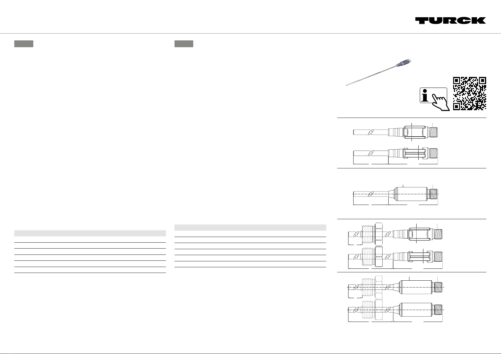
Geräteübersicht
Abbildung Typ
Abb. 2 TTM…-20…A-CF… ohne Prozessanschluss
Abb. 3 TTMS…-20…A-CF… ohne Prozessanschluss
Abb. 4 TTM…-20…A… mit Prozessanschluss
Abb. 5 TTMS…-20…A… mit Prozessanschluss
Abb. 6 TTM…-10…A… mit Prozessanschluss
Abb. 7 TTMS…-10…A… mit Prozessanschluss
Funktionen und Betriebsarten
Die Temperatur wird über ein Pt1000-Messelement der Klasse A erfasst und
temperaturabhängig als Analogsignal von 4…20mA in 2-Leiter-Technik
ausgegeben. Wegen der Wärmeleitung vom Fühler zur Auswerteeinheit ist
die max. zulässige Prozesstemperatur (Tmax.) von der Umgebungstemperatur
(Tamb.) abhängig, siehe Abb.8 (TTM…) und Abb. 9 (TTMS…).
DE Kurzbetriebsanleitung EN Quick-Start Guide
TTM(S)…-…LI6… Temperature Transmitter
Other Documents
Besides this document the following material can be found on the Internet
at www.turck.com:
■Data sheet
■EU declaration of conformity (current version)
For your Safety
Intended use
The devices are designed only for use in industrial areas.
The compact temperature transmitters record temperatures and convert the
temperature value into an analog output signal. The evaluation electronics
are integrated into the device.
The devices must only be used as described in these instructions. Any other
use is not in accordance with the intended use. Turck accepts no liability for
any resulting damage.
General safety notes
■The device must only be mounted, installed, operated and maintained by
trained and qualified personnel.
■The devices fulfill exclusively the EMC requirements for industrial applica-
tions and are not suitable for use in residential areas.
Obvious misuse
■The devices are not safety components and must not be used for the
protection of persons or property.
Product Description
Device overview
Figure Type
Fig. 2 TTM…-20…A-CF… without process connection
Fig. 3 TTMS…-20…A-CF… without process connection
Fig. 4 TTM…-20…A… with process connection
Fig. 5 TTMS…-20…A… with process connection
Fig. 6 TTM…-10…A… with process connection
Fig. 7 TTMS…-10…A… with process connection
Functions and operating modes
The temperature is recorded via a class-A Pt1000 measuring element and
the value is converted into an analog signal of 4 to 20mA depending on the
temperature using 2-wire technology. Due to the transfer of heat from the
probe to the evaluation unit, the maximum permissible process temperature
(Tmax.) depends on the ambient temperature (Tamb.); see Fig. 8 (TTM…) and
Fig. 9 (TTMS…).
© Hans Turck GmbH & Co. KG | 100008353 2019-08 DE EN
TTM…-…LI6…
TTMS…-…LI6…
Temperature Transmitter
Quick-Start Guide
Doc-No. 100008353 1907
Additional
information see
15 [0.59] M12 × 1
L58.7 [2.35]
9.4 [0.37]
M12 × 1
L58.5 [2.30]
16 [0.63]
15 [0.59] M12 × 1
L
I
58.7
2.35
9.4 [0.37]
5
I
TTM…-…LI6… | TTMS…-…LI6…
turck.com


