TURFCO T3000 Instruction Manual

21
85872 RevA
TURFCO T3000 APPLICATOR
Transporting the Machine to the Worksite
Whether you use trailers, carriers or a pickup, loading and unloading the T3000 Applicator is very easy using the
hydrostatic drive. Just approach the load area or ramps, get off the machine and slowly walk it into or onto the
transport device. Never, repeat never attempt to ride the machine while loading.
Unloading is just the opposite as loading. Walk slowly with the machine using the speed control to move the
machine. Do not attempt to drive the machine down ramps, carriers or trailers while riding the machine.
If you need to push the machine by hand, the transaxle has a freewheel “neutral” position so the machine can be
moved without starting the engine. Just place the transmission neutral lever in the freewheel position and it will
make the machine free wheel so you can move the machine by pushing it. WARNING - When the freewheel lever
is in the neutral position, the machine can roll away on ramps and slopes. Use the parking brake to secure
the machine.
Always use the frame when you tie the machine for transport. Do not attach ties to the fertilizer hopper, tanks or
other parts of the machine. Only use the frame for transport tie down.
Loading and Unloading using Ramps
1. Position the machine at the bottom of the ramps.
2. The operator should be off the machine standing behind the operators platform.
3. Using the Speed Control Lever slowly advance the machine forward and up the ramps into the trailer, truck or
carrier. The operator will remain off the machine the entire time.
4. Unloading is the same process. The operator will remain off the machine slowly walking the machine down the
ramps.
FRONT TIEDOWN
LOCATIONS REAR TIEDOWN
LOCATIONS
OP85872-11
FIGURE 16
PARKING
BRAKE
FREEWHEEL
LEVER
OPERATION

22 85872 RevA
TURFCO T3000 APPLICATOR
PROBLEM POSSIBLE CAUSE
GROUND SPEED
WRONG
ENGINE RPM WRONG
BENT OR MISADJUSTED TRANSAXLE ADJUSTMENT ROD
V-BELT TO TRANSAXLE DAMAGED OR MISADJUSTED
PARKING BRAKE ON OR NOT DISENGAGING
OVERLOADED
TRANSAXLE PROBLEMS
STEERING PROBLEMS DAMAGED OR LOOSE STEERING CABLES
DAMAGED OR BENT TIE RODS, WORN TIE ROD ENDS
BENT SPINDLES
FRONT WHEEL BEARINGS
EXCESSIVE NOISE OR
VIBRATION
LOOSE COVERS OR GUARDS
PUMP MOUNTS LOOSE OR DAMAGE PUMP MOUNT BEARINGS
MOTOR MOUNTS LOOSE OR DAMAGED
ENGINE PULLEY LOOSE, IDLER PULLEY BEARINGS DAMAGED OR WORN
SPREADER PROBLEMS
SPINNER NOT
ROTATING
V-BELT FAILURE OR TENSION SETTING WRONG
VARIATOR PULLEY JAMMED, VARIATOR CABLE
MISSING SPINNER SHAFT PINS
WORN OR DAMAGED SPINNER SHAFT BEARING IN HOPPER
WORN OR DAMAGED SPINNER SHAFT DRIVE PULLEY BEARING
POOR SPREAD GATE SETTING WRONG OR GATE NOT OPENING
VARIGATE SETTING WRONG
DEBRIS IN GATE
GATE CONTROL CABLE NOT OPERATING
BORDER CONTROL HEIGHT
ACCUWAY SETTING WRONG
ENGINE RPM
GROUND SPEED
SPREADING HEAVY
TOWARDS LEFT OR
RIGHT SIDE
ACCUWAY SPREAD PATTERN ADJUSTER SETTING WRONG
OPERATION
TROUBLESHOOTING TABLE

23
85872 RevA
TURFCO T3000 APPLICATOR
PROBLEM POSSIBLE CAUSE
SPRAYER PROBLEMS
NO PRESSURE OR
LOW PRESSURE
BLOCKED FILTER
SHUTOFF VALVE IN OFF POSITION
PUMP V-BELT FAILURE OR TENSION WRONG
PUMP FAILURE
HOSES FROM TANK TO PUMP BLOCKED OR KINKED
HOSES FROM PUMP TO REGULATOR BLOCKED OR KINKED
PRESSURE REGULATOR FAILURE OR SET WRONG
SYSTEM AIR LOCKED, VENTS ON TANK CAPS BLOCKED
PRESSURE BUT NO
SPRAY
BLOCKED SPRAY TIPS
BLOCKED FILTER
DAMAGED SPRAY CONTROLS
DAMAGED OR KINKED HOSES TO SPRAY TIPS
OSCILLATING PUMP
PRESSURE NEEDLE
(RAPID 10+ LBS.
MOVEMENT)
SYSTEM LEAKS
KINKED HOSE
FILTER BLOCKED
PRODUCT LEVEL IN TANKS TOO LOW
BAD PUMP
PRODUCT IN TANKS FOAMING - KEEP TANKS 1/3 FULL
POOR SPRAY MISSING SPRAY TIPS
BLOCKED SPRAY TIPS
PRESSURE SETTING WRONG
SPRAY TIP MOUNTING ANGLES WRONG
SYSTEM LEAKS DAMAGED OR LOOSE HOSES
PUMP FAILURE, PUMP LEAKING AT SEALS, REPLACE PUMP
DAMAGED OR CRACKED FITTINGS
DAMAGED OR LOOSE O-RINGS ON FITTINGS
DAMAGED TANKS OR TANK FITTINGS
OPERATION
TROUBLESHOOTING TABLE

24 85872 RevA
TURFCO T3000 APPLICATOR
SERVICE AND MAINTENANCE
Operator Daily Inspection
INSPECTION - A general inspection is a good idea
before the machine is ready to used or put away.
Before and after each use, check the following items:
● Inspect for damaged or missing guards or covers.
Do not operate any machine with missing or
damaged guards.
● Inspect entire T3000 for damaged or inoperable
components. Do not operate any machine with
damaged or inoperable components.
WARNING
OP85872-12
FIGURE 17
SPREADER GATE LEVER
SPREADER HOPPER
SPINNER WHEEL
SPRAY NOZZLES
FRONT COVER
SPINNER WHEEL
UPPER PULL PIN
SPINNER WHEEL
LOWER PULL PIN
TANK DRAIN PLUG
(ONE PER SIDE)
SERVICE AND MAINTENANCE
TO AVOID SERIOUS INJURY,
Do Not Service, Inspect, Lubricate Or
Adjust The T3000 With Any Part of the
Sprayer or Spinner Assembly Operating
or With the Engine Running.
All Of The Service And Adjustment Procedures
Involve Or Are Near Rotating And Moving Parts.
Work Safely, Follow All Hazard Warnings, Decals,
Safety Precautions And Wear The Appropriate
Safety Gear.
● Inspect the entire machine for loose fasteners.
Retighten as required.
● Inspect all the operator controls for proper
operation.
● Check the tires for proper inflation.
● Inspect the spinner assembly spinner wheels.
Check for proper alignment, damage, wear, and
missing hardware.
● Check for a buildup of fertilizer on spinner assembly
components and the hopper gate. Check for a
buildup on and under the spinner wheels. Check
for debris caught in spinner wheel.
● Check for a buildup of fertilizer on components
under the hopper.
● Periodically inspect the steering cables for wear
or damage.
● Protect from rust and moisture with a very light
coating of machine oil.
INSPECTION OF THE V-BELTS - The lower front
cover needs to be removed so you can clean or inspect
the belts. To remove the cover, twist out the four screw
and slide the cover forward. You may now inspect the
belts clean or grease the belt idler.

25
85872 RevA
TURFCO T3000 APPLICATOR SERVICE AND MAINTENANCE
Storage
TO STORE THE T3000 OVER AN EXTENDED
PERIOD, perform a complete inspection. Refer any
needed service or repair to service level personnel.
● Completely clean the hopper and spinner wheel.
Use low pressure wash, DO NOT use high
pressure wash.
● Perform a complete lubrication procedure.
● Lubricate engine in accordance with the engine
manufacturers instruction.
● Lubricate all grease fittings.
● Empty the engine fuel tank
● Apply a film of light machine oil to the pivot points,
ball joints, steering components and engine to
control rust.
● Flush and drain the tanks. Leaving caustic
products in the system for storage could damage
the pump and hoses. (See Protection Against
Freeze Damage in the Winter Storage section)
● To protect the rubber and plastic parts, store the
T3000 out of direct sunlight.
TO RETURN TO SERVICE AFTER EXTENDED
STORAGE, inspect the entire machine for any dam-
age that may have occurred during storage.
● Perform a complete lubrication procedure.
Lubricate engine in accordance with the engine
manufacturers instruction. Refer any needed
service or repair to service level personnel.
Winter Storage
Protection Against Freeze Damage
The pump, tanks and spray system must be protected
from freezing during storage. Use the following steps-
● Flush the entire spray system with clean water. Run
the pump until the tanks are completely empty and
water not longer sprays from the tips and the hand
held wand.
● Stop the engine and remove the cap from the strainer.
Allow any water to drain from the pump and hoses.
Replace the cap.
● Put 1 gallon of RV antifreeze in each tank.
TANKS MUST BE FLUSHED WITH WATER. DO
NOT PUT ANTIFREEZE IN WITH CHEMICAL
OR FERTILIZER AS A CHEMICAL REACTION
CAN OCCUR. CHEMICAL REACTIONS CAN
RELEASE HARMFUL AND TOXIC GASSES.
● Run the pump to circulate the antifreeze in the
system.
● Open each valve one at a time until antifreeze sprays
from the tips. Use the hand held spray wand until
antifreeze sprays from the tip.
Do not spray out all of the RV antifreeze, allow
antifreeze to remain in strainer cap, pump,
controls and tanks.
DANGER
CLEANING
IMPORTANT!!
Keeping the machine clean and free of
fertilizer and chemical residue is critical to the
life of the machine. Always wash the machine
until it is clean and free of fertilizer everywhere.
Fertilizer left on the machine will ruin the
paint and cause corrosion. This will damage
the machine and be the cause of failures later.
● Wash the entire machine with a hose or a low
pressure washer.
● Avoid high pressure washing around bearings.
● Wash out the Fertilizer hopper.
● Move the gate opening lever while washing to make
sure the gates are clean and free of chemicals.
● Clean the carburetor governor springs and
linkages weekly. Refer to Lubrication Section in
this Manual.
● Once clean, apply light machine oil to control rust.
Refer to Lubrication Section in this Manual.
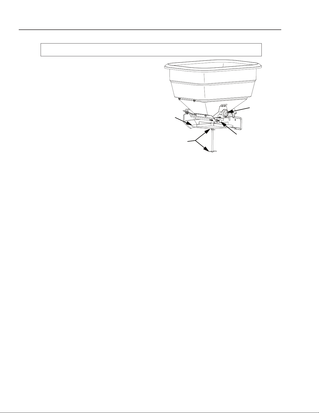
REMOVAL OF THE SPINNER WHEEL (See Figure
18) - The spinner wheel can be removed to aid in
inspection and cleaning. First remove two spinner
wheel pull pins. One from under the spinner and
one on the bottom of the spinner shaft. Then pull the
spinner shaft up and through the bottom of the fertilizer
hopper. To replace the spinner shaft and spinner just
do the reverse and replace the front cover.
SV85872-11
SPINNER
WHEEL
FIGURE 18
SPINNER
WHEEL AND
SPINNER SHAFT
PULL PINS

26 85872 RevA
TURFCO T3000 APPLICATOR
SERVICE AND MAINTENANCE
ENGINE
OIL DIPSTICK
AND FILLER
ENGINE
AIR CLEANER
TRANSAXLE
RESERVOIR
TANK
REMOVE STORAGE TRAY
TO CHECK ENGINE
FIGURE 19
SV85872-02
GREASE FITTING LOCATIONS
(TOTAL OF 6)
AS VIEWED FROM BOTTOM
REAR OF MACHINE
FRONT AXLE
CENTER SWIVEL (QTY 1)
RIGHT FRONT
WHEEL BEARING (QTY 1)
FRONT
STEERING
ARMS
(QTY 2)
IDLER ARM
SUPPORT (QTY 1)
LEFT FRONT
WHEEL BEARING (QTY 1) FIGURE 20 SV85872-03
ENGINE AND TRANSAXLE (See Figure 19)
Engine: CHECK OIL LEVELS DAILY. Follow the
engine manufacturer’s manual for intervals of oil
change, oil filter replacement, proper oil types, and
fill levels for the engine. Inspect and clean/replace
the engine air filter as needed.
Engine Carburetor Linkages and Springs:
CLEAN AND LUBRICATE WEEKLY. Clean and
remove fertilizer dust from the linkages, governor
springs, choke linkage on the carburetor with carb
cleaner. Lightly lubricate to protect from rust. Wipe
away excess lubrication that will attract and collect
dust, dirt and debris.
Transaxle: Check the level of fluid in the transaxle
reservoir. Fill only to the “Full Cold” level mark on
the reservoir (located very low on reservoir). Use
20W/50 engine oil for the transaxle. Do not overfill.
Transaxle capacity is 95.5 fluid ounces (2.8 Liter/3
quarts). Add extra to allow for filter, the reservoir
and the reservoir hose (approximately one quart).
GREASE FITTINGS (See Figure 20)
Grease Fittings: (qty 6) Grease after every 8 hours
of operation. Wipe away excess lubrication that will
attract and collect dust, dirt and debris.
Lubrication

27
85872 RevA
TURFCO T3000 APPLICATOR SERVICE AND MAINTENANCE
WHEN TO
PERFORM
SERVICE
DAILY
WEEKLY
5 HOURS
25 HOURS
50 HOURS
75 HOURS
100 HOURS
150 HOURS
200 HOURS
250 HOURS
300 HOURS
350 HOURS
400 HOURS
450 HOURS
500 HOURS
550 HOURS
600 HOURS
650 HOURS
700 HOURS
750 HOURS
800 HOURS
850 HOURS
900 HOURS
950 HOURS
1000 HOURS
WASH AND CLEAN UNIT
INSPECT HARDWARE
X
CHASSIS LUBE
GREASE FITTINGS (6) X
ENGINE
CHECK OIL LEVEL
CHANGE OIL
CHANGE OIL FILTER
CHECK/CLEAN AIR
FILTER
CHANGE AIR FILTER
CLEAN CARB LINKAGE
X
X
X
X
X
X
X
X
X
X
X
X
X X
X
X
X X
X
X
X X
X
X
X X
X
X
X X
X
X
X X
X
X
X X
X
X
X X
X
X
X X
X
X
TIRES
AIR PRESSURE X
TRANSAXLE
CHECK FLUID LEVEL
CHANGE FLUID
CHANGE FILTER
X
X
X
X
X
X
X
SPRAYER
CLEAN AND INSPECT
CLEAN NOZZLES
CLEAN STRAINER
SCREEN (FILTER)
X
X
X
SPREADER
CLEAN AND INSPECT
LUBE GATE
X
X
V-BELTS
INSPECT TENSION X
STEERING CABLES
CHECK AND ADJUST
X XXXXXXXXXXXXXXXXXXX
Recommended Service Schedule
REAR OF MACHINE
PUMP FIGURE 21
SV85872-04
STRAINER CAP SHUTOFF HANDLE
AS VIEWED FROM BOTTOM
LOCATION OF SPRAY
SYSTEM SHUTOFF VALVE
AND STRAINER SCREEN
(See Figure 21)
When the handle on the shutoff
valve is pulled down, flow from
the tanks is stopped (closed).
Remove the strainer cap
to access the screen (filter)
for cleaning. The cap on
the strainer should only be
removed when the shutoff
valve is closed.
NOTE: When the strainer cap
is remove, some fluid from the
pump will be present.

28 85872 RevA
TURFCO T3000 APPLICATOR
SERVICE AND MAINTENANCE
FIGURE 22
PEDAL HEIGHT ADJUSTING
ROD CLEVIS NUT
SV85872-10
GROUND
SPEED
CAMSHAFT
BLACK PLASTIC
LOCKING BLOCK
BLACK PLASTIC
LOCKING BLOCK
PEDAL
CONTROL ROD
CONTROL ROD
LOCATION OF
SMALL PLASTIC
BEARING
● Adjust pedal height by unlocking on clevis nut and
turning control rod at clevis. Turning the rod in
(shorter) will lower the pedal height.
● Check pedal height. Pedal should be 1-3/4” to
2” inches above the rubber pad on the operators
platform (when not depressed).
● Reattach upper end of control rod to camshaft and
secure with cotter pin.
● Reattach spring to control rod. Pedal should return
to raised position when released.
Step 3. (See Figure 22) Check adjustment.
● Locking nut on clevis tight.
● Spring reattached to the control rod.
● Small plastic bearing in the hole in the camshaft
where the upper end of the control rod is attached
is in place.
● Pedal returns to raised position and unlocks speed
control when released.
● Pedal maintains speed control when depressed.
ADJUSTING GROUND SPEED CONTROL PEDAL
(See Figure 22)
The ground speed control pedal can be adjusted if it
no longer will maintain the ground speed lock or to
correct the pedal height. Use the following steps to
adjust the ground speed control pedal.
Secure the machine, Locate the machine on a level
surface. All work can be done from underneath the
machine.
Step 1. (See Figure 22) Inspect the pedal, control
rod and camshaft before adjustment.
● Check pedal for damage. Control rod should be
straight.
● Check that spring is attached to the control rod
(located midway on the rod).
● Check that the black plastic locking block is not
worn or damaged. Note: If equipped with a white
plastic block, replace with current production black
plastic block.
● Check that the small plastic bearing in the hole in
the camshaft (where the upper end of the control
rod connects) is not worn.
Step 2. (See Figure 22) Adjust Control Rod to
correct pedal.
● Disconnect the spring from the control rod.
● Remove the cotter pin securing the upper end of
the control rod to the camshaft. Disconnect from
camshaft.

29
85872 RevA
TURFCO T3000 APPLICATOR
ADJUSTING
STEERING CABLES
(See Figure 23)
The steering cables
can be adjusted to
correct for wear and to
take “slack” out of the
steering wheel.
● Inspect the tie rods
and tie rod ends.
● Check the front
wheel bearings and the
bearings where the front
spindles go through the
front axle beam.
● Check that cables are
on steering cable pulleys
at rear of machine
● Locate adjusters on
cable ends near front axle. Loosen locking nuts on both cables. Adjust each side equally to keep the alignment
equal and to avoid changing the steering wheel steering position. Do not over tighten cables. Retighten lock nuts
after adjusting.
● Check the alignment of the front tires, they should have a “Tow Out” of 1/4” to 1/2”. Take a measurement across
the front tires, measuring from the center of the tires. Measure both the front and the rear. The front measurement
should be 1/4” to 1/2” more than the rear measurement. Correct if needed by adjusting the tie rods.
ENGINE
PULLEY TRANSAXLE
PULLEY
HOPPER
PULLEY
PUMP PULLEY
VARIATOR
PULLEY
SV85872-09
TENSIONER PULLEY FIGURE 24
A
B
C
D
E
REDUCTION
PULLEY
SERVICE AND MAINTENANCE
V-BELT IDENTIFICATION (See Figure 24)
A. Hopper Pulley to Variator Pulley - 24” 3L SECTION
B. Variator Pulley to Reduction Pulley - 27” 3L SECTION
C. Reduction Pulley to Pump Pulley - 27” 3L SECTION
D. Pump Pulley to Engine Pulley - 26” 3L SECTION
E. Engine Pulley to Transaxle Pulley - A SECTION A-38
REAR OF MACHINE
FIGURE 23
SV85872-12
STEERING CABLE ADJUSTERS
STEERING CABLE PULLEYS
SET TOW OUT AT
REAR MEASUREMENT
PLUS 1/4” to 1/2”
TIE RODS
REAR MEASUREMENT
AS VIEWED FROM BOTTOM

30 85872 RevA
TURFCO T3000 APPLICATOR
Calibration of Spreader
Calibrate the machine for product desired. See the product label for application rates.
Calibration should only be done by licensed persons.
The T3000 has two spreader widths -
● 18 foot wide for a 9 foot effective width
● 12 foot wide for a 6 foot effective width.
You are using a Spyker Spreader that requires a 100%
overlap for best coverage. Therefore 18’ foot equals 9’
foot and 12’ foot equals 6’ foot wide.
Because you have two spinner speeds for wide and
narrow, we will need to calibrate two gate opening
settings. One for 18/9 foot and one for 12/6 foot wide.
The procedure for both is the same using the Spreader
Gate Rate Adjuster Dial on the front of the hopper.
Two facts you need to know before you begin -
● The ground speed of your unit.
● The pounds of fertilizer per 1000 sq. ft. you want to spread.
Time the speed of your machine - At full throttle, drive the machine in a straight line for 111 feet. The time it takes
should be 15 seconds. That means you will cover 1000 sq. ft. every 15 seconds when spreading a 18/9 foot wide swath.
Next drive your unit in a straight line for 166 feet. The time should be 23 seconds. That means you will cover 1000
sq. ft. every 23 seconds spreading a 6 foot swath
Note: Your times may be off a second or so due to temperature, weight and other elements. As long as you are
within a second or so of 15 and 23 do not worry about the times. Write your times down.
Calibration for 4 lbs of fertilizer per 1000 sq. ft. at 18 / 9 foot spread pattern.
Step 1. Start with an empty hopper. Remove the spreader spinner wheel and shaft. Remove the pull pin at the very
bottom of the shaft under the bearing and remove the pin that holds the spinner wheel in place. Pull the shaft up
and out of the hopper removing the spinner wheel. Place a pin in the shaft and set it back into the hole to prevent
fertilizer from falling out.
Step 2. Remove the plastic carrying tray from behind the hopper and place it under the hopper to catch the fertilizer.
This saves the fertilizer and makes clean up easy.
Step 3. Set the white plastic gate rate adjuster dial on the front of the hopper so the silver pointer lines up with 5.2
on the cam wheel. The pointer sliding up to the cam is what determines the gate opening inside the hopper. Note:
The white cam is calibrated into ones and tens. Each number has 10 clicks between them so make note of your
settings. Example - 5 plus 2 clicks is 5.2 for an opening setting.
Step 4. Move the spreader gate control handle to make sure the gate is operating correctly.
Step 5. Fill the hopper with at least 20 lbs of fertilizer.
Step 6. Move the Spreader Gate Control Handle to the right or out from the machine so it misses the Vari-Rate Gate Stop.
Step 7. Open the fertilizer gate by pushing the Spreader Gate Control Handle forward all the way, allow the spring to snap
it forward. Time the fertilizer flow for one minute (4 times the 15 seconds speed). That is equal to 4000 sq. ft. of coverage.
Note: During this procedure you will need to shake the hopper to simulate driving vibration and move the fertilizer
from under the gate so it does not slow down the flow.
Step 8. After one minute of flow weigh the fertilizer in the green plastic tray. There should be 16 pounds total in the
tray enough for 4000 sq. ft. Divide that by 4 and you get 4 lbs per 1000 sq. ft.
Step 9. If you did not get 16 lbs., you will need to try again. Less than 16 open the gate a couple clicks. More than
16 reduce the gate setting a couple clicks. Then repeat steps 7 and 8 until you get the correct setting you require.
Write down this setting noting that it is for this fertilizer at 4 lbs per 1000 sq. ft. on an 18/9 foot spreading swath.
OP85872-29A
FIGURE 25
“ACCUWAY”
SPREAD PATTERN
ADJUSTER
SPREADER
GATE RATE
ADJUSTER
DIAL
SPREADER
SPINNER
WHEEL
SPREADER
SPINNER
WHEEL PULL PINS
CALIBRATION

31
85872 RevA
TURFCO T3000 APPLICATOR CALIBRATION
Calibration for 4 lbs of fertilizer per 1000 sq. ft. at 12/6 foot spread pattern.
All the steps for the 12/6 calibration are the same as the 18/9 spread with the exception of Step 3 and Step 7. You
will need to change the gate rate adjuster dial and use the 23 seconds to cover 166 running feet timing to get the
1000 sq. ft. with a 6 foot wide effective swath.
Step 3. Change the gate rate adjuster dial setting to be closer to 4.5 on the dial.
Step 7. Change your ground speed to be 4 times the 23 seconds speed for a total of 92 seconds to cover 4000 sq.
ft. with a 6 foot wide swath.
Be sure to write this setting down as the gate rate adjuster dial setting for a 12/6 foot effective swath for this fertilizer.
When you finish with this calibration you will be ready to set the Vari-Rate Gate Stop.
Setting the Vari-Rate Stop (See Figure 26)
This is the adjustable stop next to
the gate opening lever on the top
right of the unit. This is the setting
you will use when you applicate
on the narrow spinner setting for a
12/6 foot effective width. It comes
into use when you push the Gate
Opening Handle to the left or
inwards toward the machine. This
will allow you to have two settings
in the machine at all times.
The Vari-Rate stop limits the
spreader gate opening to 60% of
the spreader gate rate adjuster
dial setting you calibrated earlier.
This will be your 60% setting for
trimming or 60% of a full application
for smaller areas.
Step 1. Set the white cam on the front of the hopper to the correct number for a 12/6 foot effective swath for a
particular fertilizer.
Step 2. Loosen the Locking Knob holding the Vari-Rate Stop in place so it moves all the way forward.
Step 3. Moving the Gate Opening Handle to the left or in towards the machine push it ahead so it is against the
Vari-Rate Stop.
Step 4. You will now need to look inside the hopper to watch the gate opening. Move the Vari-Rate Stop and the
Gate Opening Handle backwards toward the rear of the machine very slowly. When the gate in the bottom of the
hopper starts to move just a little, STOP AND HOLD IT RIGHT THERE. Screw in the Locking Knob on the Vari-Rate
Stop locking it where it is. Make sure the big black plastic nut is VERY TIGHT. Test the gate several times to make
sure it is opening the gate to the proper setting using just the Vari-Rate Stop.
Step 5. Now you can move the white cam on the front of the hopper to the setting for 18 / 9 foot effective.
Result: You have now set two calibrations into your machine. When you want to spread 12 / 6 foot wide you
move the lever on the left to narrow and open the Gate Opening Lever against the Vari-Rate Stop and you will be
spreading a 12 / 6 foot effective swath accurately.
When you move the lever on the left to the wide spread and the Gate Opening Handle to the right and forward you
will be spreading a 18 / 9 foot effective swath.
SPREADER CALIBRATION CONTINUED ON NEXT PAGE
LOCKING
KNOB
OP85872-10
FIGURE 26
VARI-RATE
GATE STOP
HANDLE TIPPED
OUT TO BYPASS
VARI-RATE STOP
HANDLE PUSHED
FULLY FORWARD
FOR 100%
GATE OPENING
SPREADER GATE
CONTROL HANDLE PUSHED
FORWARD TO VARI-RATE 60%
STOP SETTING

32 85872 RevA
TURFCO T3000 APPLICATOR
Material drops out of the hopper just behind the center of
the wheel (spinner wheel rotates clockwise).
Product that lands closer the center of the spinner wheel
has father to travel on the wheel as it moves to outside edge
to be thrown. As a result of staying on the wheel longer, it
gets thrown out last - or to the right.
Product that lands closer the outside edge of the spinner
wheel is thrown first. It is on the wheel for a shorter time
and is thrown out first - or to the left.
Adjust your Accuway to give a even balanced left to right
spread. Start with an empty hopper -
● Open the gate all the way. Look straight down into the
opening, you will see the black plastic Accuway wedge.
● Screw the adjuster knob (on front of hopper) so the
Accuway moves into the gate opening. Move the
Accuway far enough forward so that 3/8” of an inch is
visible in the opening.
● To adjust the throw more to the left, increase the amount
that the Accuway is visible in the opening.
● To adjust the throw more to the right, decrease the
amount that the Accuway is visible in the opening.
● Continue moving the wedge until you get the left to right
balance spread of the product.
Note: The Accuway pattern adjuster needs to be changed when the gate opening size is changed (recalibrated) or product type is changed.
“ACCUWAY”
SPREAD
PATTERN
ADJUSTER
OP85872-27revA
3/8” INCH
GATE
OPENING
FRONT OF MACHINE
FIGURE 27
FRONT
EDGE
OF GATE
CALIBRATION
OP85872-33RevA
If It Throws to Much
to the Right - The
Accuway Is Need To
Be Further In To The
Gate Opening.
Adjust The Accuway To Get a Spread That
Is Balanced Left and Right
FRONT OF MACHINE
If It Throws to Much to the
Left - The Accuway Is Too
Far In To The Gate
Opening.
SPINNER
WHEEL
GATE
OPENING
ACCUWAY
Setting the “Accuway” Spread Pattern Adjuster (See Figure 25 and 27)
The Accuway Spread Pattern Adjuster is a black plastic wedge that is under the spreader gate opening. When
the gate is opened, the Accuway wedge controls where the material lands on the spinner wheel. This affects
the throw of the material. If the material lands closer to the center of the wheel, it spreads more material to the
right. If it lands closer to the outside edge of the wheel, it spreads more material towards the left.

33
85872 RevA
TURFCO T3000 APPLICATOR
OP85872-32
DATE
GATE
DIAL
SETTING
Spreading Calibration Record
NARROW SPREAD WIDE SPREAD
SECONDS
TO
TRAVEL
111' FEET
PRODUCT
BEING
SPREAD
DATE
GATE
DIAL
SETTING
SECONDS
TO
TRAVEL
166' FEET
PRODUCT
BEING
SPREAD
CALIBRATION

34 85872 RevA
TURFCO T3000 APPLICATOR
CALIBRATION
Calibration of Sprayer
Calibrate the machine for product desired. See the product labels for application rates.
Calibration should only be done by licensed persons.
FULL SPRAY NOZZLE
OP85872-34
TANKS
FIGURE 28
PUMP
PRESSURE
GAUGE
FULL
SPRAY
CONTROL
PSI (KPA)
I
N
C
R
E
A
S
E
D
E
C
R
E
A
S
E
SPRAY CONTROL
SPRAY GUN
TRIM SPRAY FULL SPRAY
FORWARD
REVERSE
FORWARD
REVERSE
SPRAY
PRESSURE
+
-
OFF
ON
PSI (KPA)
I
N
C
R
E
A
S
E
D
E
C
R
E
A
S
E
OFF
ON
OFF
ON
+
-
PUMP PRESSURE CONTROL KNOB
SHOULD ONLY BE
ADJUSTED BY LICENSED PERSONS!
PUMP
PRESSURE
CONTROL
KNOB
The Turfco 3000 Applicator is designed to be used on large or small turf areas.
● For large turf areas you will want to calibrate for a 9 foot wide effective application width. A 9 foot wide application
means that when you travel 111 feet you will cover 1000 sq. ft. of turf.
● For small turf areas you will want to calibrate for a 6 foot wide effective application width. A 6 foot wide
application means that when you travel 166 feet you will cover 1000 sq. ft. of turf.
Each manufacturer of product (chemical) will have different application rates and different mixtures (dilution)
for their product. You must refer to the product label to find the proper rate of application and to find the proper
premix (dilution) of your product. You must properly premix your product outside of the T3000 tanks before adding
or filling the tanks.
We will use an example of spraying 1 quart of premixed product on 1000 square feet of turf at 5MPH with a 9
foot spray for large areas and an example of spraying 1 quart of premixed product on 1000 square feet of turf at
5MPH with a 6 foot spray for smaller areas.
You will have to do a calculation on your own to match the application rate for your specific product if they differ
from the 1 quart per 1000 square feet. Your calibration will be based on your measured speed and the amount of
product being applied to 1000 square feet.
REMEMBER, all hydraulic driven machines will vary in ground speed for different reasons so you must time your
machine to properly calibrate it. Write this down. Use the tables on pages 36 and 37 to record your times and
settings. Do this often, the time will change as your machine “breaks in” or ages,

35
85872 RevA
TURFCO T3000 APPLICATOR CALIBRATION
Calibration of Sprayer for 9 Foot Wide Effective for Large Areas
Setting the sprayer application rate for 1 quart per 1000 sq. ft. at 5 mph and 9 foot wide effective spray swath.
1. Put a few gallons of WATER in the tanks. Water only no chemicals.
2. Start engine, set the engine speed to full throttle. The pump will now be operational.
3. Place a container under the full spray nozzle to catch the water.
4. Set the pump pressure using the pump pressure control knob on the control console. With all of the spray
control handles off, turn the knob in for more pressure or out for less pressure. Start with the pressure set at
40 PSI. This is an approximate setting to begin the process.
5. Time your unit to see how long it takes to travel 111 feet (this should be around 15 seconds). With a 9 foot
wide spray it takes 111 feet for the unit to cover 1000 sq. ft.
6. Open the full spray control (far right red lever) for 60 seconds (4 times the 15 second speed) and measure
the amount collected at the full spray tip. Divide by 4 and this will give you the rate for 1000 sq. ft. (at 9 foot
wide and 5 mph).
7. If the amount is less than 1 quart per 1000 sq. ft. you will need to increase the pressure (turn the pressure
knob clockwise). More than 1 quart you will need to decrease the pressure (turn the pressure knob counter
clockwise). Setting the pressure with the nozzle spraying will give a more accurate setting.
8. Run the test again and continue until you get to the 1 quart per 1000 sq. ft. application rate.
9. Check the width of the spray pattern. To do this, spray the unit on a paved area for about one minute or until
the area is very wet. Measure the width of the spray pattern. It should be about 2 feet wider than the effective
9 foot swath or 11 to 12 foot. You do want a little extra width for an effective overlap of the next pass. If the
pattern is not wide enough you can move the nozzle up a little to increase the width. If the width is too wide
you can aim the nozzle down a little more to decrease the width.
Calibration of Sprayer for 6 Foot Wide Effective for Smaller Areas
Setting the sprayer application rate for 1 quart per 1000 sq. ft. at 5 mph and 6 foot wide effective spray swath.
1. Put a few gallons of WATER in the tanks. Water only no chemicals.
2. Start engine, set the engine speed to full throttle. The pump will now be operational.
3. Place a container under the full spray nozzle to catch the water.
4. Set the pump pressure using the pump pressure control knob on the control console. With all of the spray
control handles off, turn the knob in for more pressure and out for less pressure. Start with the pressure set
at 12 PSI. This is an approximate setting to begin the process.
5. Time your unit to see how long it takes to travel 166 feet (this should be around 23 seconds). With a 6 foot
wide spray it takes 166 feet for the unit to cover 1000 sq. ft.
6. Open the full spray control (far right red lever) for 92 seconds (4 times the 23 seconds speed) and measure
the amount collected at the full spray tip. Divide by 4 and this will give you the rate for 1000 sq. ft. (at 6 foot
wide and 5 mph).
7. If the amount is less than 1 quart per 1000 sq. ft. you will need to increase the pressure (turn the pressure
knob clockwise). More than 1 quart you will need to decrease the pressure (turn the pressure knob counter
clockwise). Always set the pressure with the nozzle spraying for a more accurate setting.
8. Run the test again and continue until you get to the 1 quart per 1000 sq. ft. application rate.
9. Check the width of the spray pattern. To do this, spray the unit on a paved area for about one minute or
until the area is very wet. Measure the width of the spray pattern. It should be about 2 feet wider than the
effective 6 foot swath or 8 to 9 foot. You do want a little extra width for an effective overlap of the next pass.
If the pattern is not wide enough you can move the nozzle up a little to increase the width. If the width is too
wide you can aim the nozzle down a little more to decrease the width.

36 85872 RevA
TURFCO T3000 APPLICATOR
OP85872-23
DATE
PUMP
PRESSURE
SETTING
6' Foot Wide Spray Calibration Record
6' FOOT WIDE SPRAY 6' FOOT WIDE SPRAY
SECONDS
TO
TRAVEL
166' FEET
PRODUCT
BEING
SPRAYED
DATE
PUMP
PRESSURE
SETTING
SECONDS
TO
TRAVEL
166' FEET
PRODUCT
BEING
SPRAYED
CALIBRATION

37
85872 RevA
TURFCO T3000 APPLICATOR CALIBRATION
OP85872-23
9' Foot Wide Spray Calibration Record
9' FOOT WIDE SPRAY 9' FOOT WIDE SPRAY
DATE
PUMP
PRESSURE
SETTING
SECONDS
TO
TRAVEL
111' FEET
PRODUCT
BEING
SPRAYED
DATE
PUMP
PRESSURE
SETTING
SECONDS
TO
TRAVEL
111' FEET
PRODUCT
BEING
SPRAYED
Table of contents
Other TURFCO Farm Equipment manuals
Popular Farm Equipment manuals by other brands

Bomford Turner
Bomford Turner WREN 2.7 Instruction Book & Replacement Parts Listing

Multiva
Multiva 300C Operation and maintenance manual

Spudnik
Spudnik 560 Owner's/operator's manual

EASY COOPS
EASY COOPS Chicken Coop Plan 6x6 Assembly instructions

USC
USC LPV100 Operator's manual

Toro
Toro Reelmaster 03486 Operator's manual

Raven
Raven Case IH Patriot 3XX0 Guidance and Steering Installation Manual

CrustBuster
CrustBuster Seed Tender 160 owner's manual

Aitchison
Aitchison SEEDMATIC PROFESSIONAL 8140 manual

Titan Attachments
Titan Attachments 72RBGRAP Operator's manual

Yetter
Yetter TITAN 2960-021A Operator's manual

Pottinger
Pottinger MERGENTO VT 9220 Operator's manual