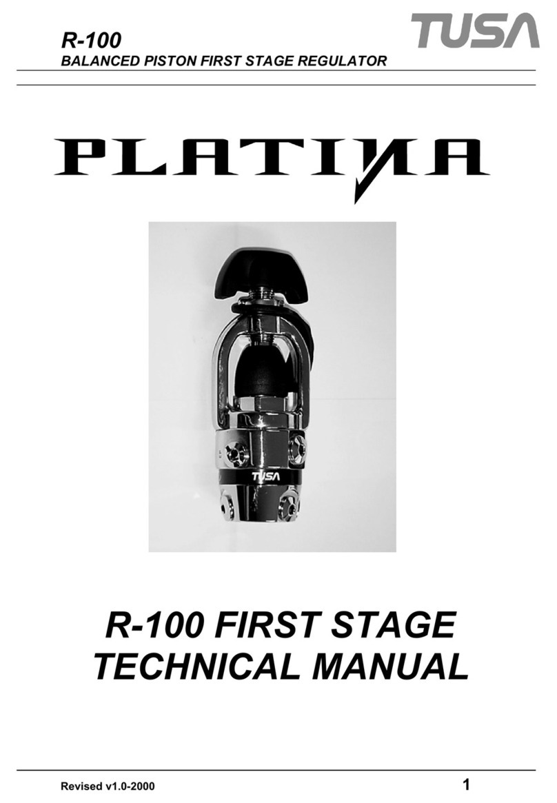
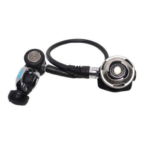
Tusa RS-606 User manual

The Enriched Air Nitrox (EAN) Policy
TUSA regulators are built with a high level of care using quality components and lubricants. The
following TUSA regulators in Standard condition have passed required testing for Enriched Air Nitrox
(EAN) use by the ASTM (American Society for Testing and Materials) G-175 test protocols.
Regulator Models: R-600, R-500, R-300 It has been confirmed as the results of fire tests for these
Standard regulators that fire will not affect the internal components of the products and that the
products will not cause fire to spread.
This means that these Standard regulators can be used with EAN having an oxygen mixture ration
equal or less than 40% and standard compressed air alternately.
EAN mixtures equal or less than 40% oxygen will not affect the internal components of the products
and consequently the products have a reduced combustion risk.
The major premise, however, of this statement is that clean compressed air must be used in this
case. If compressed air without this guarantee is used, the product must be overhauled prior to any
subsequent use of the product with EAN having an oxygen mixture ratio equal or less than 40%.
Warning
• Due to a high possibility of combustion never use EAN having an oxygen mixture ratio higher than
41% under any circumstances.
• If it is the intent of the owner to use the regulator with standard compressed air and with Enriched
Air Nitrox (EAN) clean oxygen-compatible compressed air must be used at all times.
• Non oxygen-compatible compressed air may contain hydrocarbons that contaminate the regulator
components. This contamination can cause combustion when combined with EAN mixtures.
• If unclean compressed air (usually occurring when the infilling compressor oil component becomes
mixed into the air) is used in the regulator and subsequently, EAN (with an oxygen mixture ratio
lower than 40%) is used, the remaining contamination inside the regulator greatly increases the
possibility of ignition.
Caution
• Regulator models not listed above have not been properly tested for use with Enriched Air Nitrox
(EAN).Therefore, use with EAN should be avoided at all times.
TABATA CO., LTD. JAPAN
1-3-17, Higashikomagata, Sumida-ku, Tokyo, Japan 130-0005
TEL 03-3624-2816/FAX 03-3623-9902 (Country Code=81)
TABATA MFG. [TAIWAN] CO., LTD.
No.256, Huanqu W. Rd., Dayuan Township, Taoyuan County 337, Taiwan.(R.O.C.)
TEL.03-386-5100/FAX.03-386-5103 (Country Code=886)
TABATA U.S.A. INC.
2380 Mira Mar Ave., Long Beach, CA 90815, U.S.A.
TEL 562-498-3708/FAX 562-498-1390 (Country Code=1)
TABATA AUSTRALIA PTY. LTD.
4D James Ruse Business Park 6 Boundary Road, Northmead, Sydney, NSW 2152, Australia
TEL 02-9890-4555/FAX 02-9890-5222 (Country Code=61)
©Copyright TABATA CO., LTD
Printed in Japan
Regulators
- 2 -
SECTION I
WARNING:READ CAREFULLY
Unless otherwise specified TUSA regulators should be used only with open circuit compressed
air breathing equipment.
Before any attempt is made to use this regulator underwater, you MUST have received training
and CERTIFICATION in the technique of sport diving from a recognized certification agency.
Use of this equipment by a person who is not certified by a recognized agency shall render
all warranties, express or implied, null and void. Use of regulators by uncertified or untrained
persons is dangerous and can result in severe injury or death. This regulator is not intended for
commercial use with surface supplied air.
Before each use, the regulator must be given a thorough visual inspection and functional test.
NEVER dive with a regulator which shows signs of damage or provides substandard
performance.
Repair, servicing, or addition of accessories (e.g. pressure gauge) to this regulator is to be
performed ONLY by a qualified TUSA Service Facility. The HP and LP outlets of the first stage
have intentionally been fitted with different threads to prevent the possibility of incorrect fitting
of accessories.
Always apply pressure to the regulator gradually by opening the cylinder valve SLOWLY,
NEVER lubricate any part of the regulator (especially the rubber O-ring seal between the
cylinder
valve and regulator) with a hydrocarbon-based lubricant.
Notice:
Model RS-606, 671, 681, 1103 and 1104 are restricted to be used above the water
temperature 10°C.
Maximum allowable working pressure is 3400 PSI (235bar).
SECTION II
DESCRIPTION AND OPERATION
2.0 GENERAL
TUSA Regulators are BALANCED PISTON and BALANCED DIAPHRAGM type SINGLE HOSE
REGULATORS. The regulator reduces high pressure air from the scuba cylinder to ambient
pressure suitable for breathing, through the operation of first and second stage regulators.
The first stage regulator reduces incoming high pressure air, to an intermediate pressure of
approximately 135PSI(≈9.5bar). The second stage regulator, using a diaphragm operated
demand valve, further reduces air from intermediate pressure to ambient pressure permitting
normal breathing. The first and second stages of the regulator are connected by a low pressure
hose. A swivel yoke (TYPE INT) on the first stage body secures the regulator to the cylinder
valve, while an O-ring surrounding the outlet orifice on the cylinder valve ensures an airtight
connection to the first stage.
TUSA REGULATORS
OWNER’S MANUAL
BEFORE USING ANY TUSA REGULATOR,
READ THIS MANUAL COMPLETELY.
13th.
Regulators
- 1 -
FOREWORD
CONGRATULATlONS! You are now the owner of one of the many fine TUSA products. Your
new regulator is built to exacting standards, using only the highest quality materials. For several
years TUSA has been developing regulators at our R&D facility in Japan under the ISO9001
International Quality Assurance System. You have purchased the newest, the most advanced
regulator for the Sport Scuba Market available today. The TUSA regulator is the first major
improvement to the conventional down stream demand valve since 1988. The second stage is
constructed of technologically advanced materials and the performance provides exceptional
aspiration flow and allows fully adjustable performance to accommodate beginner and
professional diver.
Before you use your new regulator, please read this manual carefully. The following warnings,
cautions, and notes were written to make it possible for you to enjoy your diving experience
with maximum safety.
We at TUSA want you to have many years of dependable service from your new equipment and
have many memorable and safe dives.
Thank you for purchasing one of our high quality products.
WARNING:
THIS PRODUCT IS A SCUBA DIVING DEVICE AND REQUIRES PROPER
TRAINING BEFORE USE.
Name of
Regulator
1st Stage
Model No.
2nd. Stage
Model No.
Safe 2nd. Stage
Model No.
RS-606 R-600 S0006 SS-20
RS-671 R-600 S-71 SS-81
RS-681 R-600 S-81 SS0003
RS1103 R1100 S0003 SS0005
RS1104 R1100 S0004
TABLE OF CONTENTS
FOREWORD ............................................................... 1
TABLE OF CONTENTS .............................................. 1
SECTION I ................................................................. 2
WARNING:READ CAREFULLY ................................... 2
SECTION II
DESCRIPTION AND OPERATION ............................. 2
2.0 GENERAL ............................................................. 2
2.1 FIRST STAGE ........................................................ 3
R-600 first stage .......................................................... 3
R1100 First stage ......................................................... 3
2.2 SECOND STAGE ................................................... 3
Demand system ........................................................... 3
Intake resistance .......................................................... 3
New mouthpiece .......................................................... 3
Venturi Adjustment Lever (RS-681[S-81], SS-81) ........ 3
Adjustment knob(RS-681, 671, 606, 1104, SS-81) ..... 3
S.E.A. -Sequential Exhaust Assist [PAT.P.] (RS-
681[S-81], SS-81) ........................................................ 4
SECTION III
PRE-DIVE PROCEDURES ......................................... 4
PRE-DIVE OPERATING INSTRUCTIONS .................... 4
SECTION IV
POST-DIVE PROCEDURES ....................................... 5
SECTION V
CONTAMINATED WATER DIVING ............................ 5
SECTION VII
SCHEDULED MAINTENANCE .................................. 6

Regulators
- 4 -
S.E.A. -Sequential Exhaust Assist [PAT.P.] (RS-681[S-81], SS-81)
The Sequential Exhaust Assist (S.E.A.) is an auxiliary exhaust valve, located on top of the
S-81 and SS-81 elliptical case that reduces primary exhaust resistance and significantly
decreases workload,
thus allowing the diver to be more air efficient.
SECTION III
PRE-DIVE PROCEDURES
WARNING
Do not attempt to connect low pressure hoses to the high pressure ports with the use of
an adapter. Improper connection will cause damage to the equipment and could result in
serious personal injury. Low pressure components are not intended to withstand pressures
greater than 400PSI ≈ (28bar) When installing your accessory hoses, avoid damaging the
O-ring. Tighten gently, but firmly into the first stage housing.
PRE-DIVE OPERATING INSTRUCTIONS
1. Position the tank valve so the outlet points toward the diver.
2. Remove the dust cap from the first stage inlet and place the yoke in the center of the
cylinder valve connection.
3. Position the first stage body so that the second stage hose goes over the right shoulder of
the diver.
4. Hand-tighten the yoke screw.
5. Check all the hose connections to the first and second stages. If they can be loosened by
hand, they should be tightened with a wrench before pressurizing.
6. Check the submersible pressure gauge to make sure it indicates zero pressure.
7. Open the tank valve slowly to gradually allow air into the regulator.
NOTE: During this operation, depress the second stage purge button to reduce shock to
the valve mechanism. Do not perform this operation in a cold environment below 50˚F(10˚C).
Performing this in a cold environment may cause“freeze-up”of the regulator which can lead it
to free flow. If this occurs, you should contact a TUSA authorized service center.
8. Check the submersible pressure gauge to ensure that it indicates the proper tank pressure.
9. Check the tank/regulator connection for leakage. If leakage exists, it may be caused by
incorrect mounting of the regulator on the tank valve, or by a damaged O-ring in the tank valve.
10. To confirm that the regulator delivers air properly, first exhale through the mouthpiece to
blow any foreign matter out of the second stage, then inhale. A few of these breathing
cycles should immediately indicate proper function.
11. If you are using the second stage as an Octopus regulator, it is strongly recom- mended
to utilize an Octopus plug to prevent any foreign matter from entering the second stage
through the mouthpiece.
12. When the second stage is not in your mouth, uncontrolled air delivery can take place. This
can be stopped by turning the second stage upside down and allowing it to fill with water.
Should the air delivery continue, abort the dive and have the regulator inspected by a TUSA
Authorized Service Center.
Regulators
- 6 -
SECTION VII
SCHEDULED MAINTENANCE
1. Do not assume that a regulator is in good working order because of storage or infrequent
use. Prolonged or improper storage can still result in internal corrosion and/or deterioration
of O-ring seals.
2. 2. Have your regulator cleaned and adjusted frequently. The frequency will depend upon
the amount of use given the regulator and the conditions of use. However, TUSA strongly
recommends inspection, overhaul and scheduled parts replacement at least once a year in
order to ensure the optimum functioning of the regulator. Certain parts require replacement
at specific intervals. This work must be carried out by a certified TUSA repair facility.
Freguent use such as rental equipment and/or in salt, chlorinated (swimming pool), or
polluted fresh water might require cleaning and overhaul of the regulator every three to six
months. Chlorinated water is an especially bad environment for regulators as the chlorine
chemically deteriorates the neoprene rubber components.
3. Regularly inspect the sintered filter in the inlet port of the first-stage. If it is discolored
or corroded, replacement by trained personnel is required. Also, at this point, the entire
regulator may need a general overhaul with replacement of all soft seals and non-reusable
components. Rust or aluminium oxide (grey powder) deposits on the sintered filter are
usually an indication that salt water has entered the air cylinder and caused internal
corrosion. At this time you air cylinder(s) should be internally inspected by a qualified and
competent service control facility and then cleaned, or hydrostatically tested as required.
4. Do not disassemble your regulator. There are no adjustments which can or need to be
carried out by the user. Take the regulator to a qualified TUSA dealer or service facility for
service. Ensure that only original parts are used to service your regulator.
FINAL NOTE
Frequently service your regulator, your personal safety and the mechanical integrity of
your regulator depend on it.
Regulators
- 3 -
2.1 FIRST STAGE
R-600 first stage
With the R-600, offers a compact design weight of just 630g during actual use. This allows
the R-671 to only be a total weight of just 955g for the first and second stages. The balanced
diaphragm method first stage features minimum variation in intermediate pressure in response
to changes in residual cylinder pressure and depth. The ports are in left-right symmetry (H.P.×
2, L.P. × 4) for easier attachment to tanks, even for beginners. The R-600 always supplies the
diver with stable air at any tank pressure or depth, delivering maximum breathing ease and
comfort for them.
R1100 First stage
The TUSA R1100 offers a first stage with the balanced diaphragm design. This design features
minimum variation in intermediate pressure in response to changes in residual cylinder pressure
and depth. The ports are in left-right symmetry (H.P. × 2, L.P. × 4) for easier attachment to
tanks, even for beginners.
2.2 SECOND STAGE
Demand system
The demand system is designed to significantly reduce rubbing resistance of moving parts
and air resistance. The result is smoother and more natural valve opening/closing. Lightweight
housing The second stage main unit is smaller and lighter to reduce water resistance during
diving, thus reducing the load on the face during use. The body materials are thermo plastic
resin reinforced with glass fiber for outstanding hardness and shock resistance. The materials
also offer superior tensile strength, dimensional stability, heat resistance, weather resistance
and chemical resistance.
Intake resistance
The second stage includes a director to forcibly guide air from the demand valve. That prevents
free flow while significantly lessening intake resistance. The result is one of the lightest
intake resistance values in the industry compared with products from other companies.
New mouthpiece
The new mouthpiece, developed on the basis of ergonomic engineering, further enhances the
comfort of bite, fit, and stability. Even with a light bite, a high level of stability is achieved, so
there is no fatigue from long periods of usage.
Venturi Adjustment Lever(RS-681[S-81], SS-81)
The addition of a venturi adjustment lever on the S-81 allows the regulator to power assist the
diver when underwater utilizing the natural venture effect to turn the adjustment to “DIVE”.
The diver can also adjust the lever to prevent free flow such as on a surface swim to turn the
adjustment to the other side.
Adjustment knob(RS-681[S-81], 671, 606, 1104, SS-81)
The adjustment knob also introduces a TUSA innovation, an“Easy touch”adjustment of the
breathing resistance at need. Ten full turns provides smooth, accurate adjustment for effortless
breathing.
Regulators
- 5 -
SECTION IV
POST-DIVE PROCEDURES
Providing the best possible preventative and routine maintenance before, after, and between
dives will help to ensure the maximum life of your TUSA Regulator. To achieve this goal, there
are a number of simple, yet important, routine maintenance procedures that should be
followed by the diver after each use of the equipment. The following procedures should be
diligently followed in order to obtain the maximum life and serviceability from your regulator.
1. After each day of diving, the regulator must be cleaned, inspected, and prepared for the
next use, or for storage. As soon as the regulator is removed from the air cylinder, reinstall
the dust cap over the regulator inlet port. This cap is normally attached to the First Stage
and therefore has been under water. Be sure to dry all the water out of this cap before
securing it over the inlet port. Ensure that the O-ring, if fitted, is in place inside the dust cap.
2. 2. After diving, the regulator should be soaked in warm, not over 122˚F (50˚C) water to
remove salt and mineral deposits as soon as possible. The preferred method is to attach
the regulator to a charged air cylinder, open the cylinder valve, and thoroughly soak both
the first and second stage regulators . Pay particular attention to directing water into the
mainspring cavity of the first stage regulator, the second stage mouthpiece, and the holes
in the second stage cover. Depress the purge button several times while the regulator is
submerged in water. Dry the regulator by pressing on the purge button with the mouthpiece
pointing down. Place the dust cap in position in the yoke, or over the DIN screw. Soaking
regulator parts in warm water will remove more salt and mineral deposits than will
conventional rinsing. It will loosen deposits on interior components that rinsing will not (If
no charged air cylinder is available, follow the above procedure but be very careful NOT to
depress the purge button, or leave dust cap off, when the regulator is submerged in water.
Failure to do this will allow water to enter both regulator stages and may result in internal
corrosion). Simply soak the entire exterior of the first stage thoroughly, and proceed as
above when cleaning the second stage.
3. Store in a clean equipment box, or as an alternative, seal inside a plastic bag. Store in a
clean dry place.
4. Never store the regulator while it is still connected to the diving cylinder.
5. Do not use any type of solvent to clean any part of the regulator. Do not expose any part of
the regulator to silicone spray, as some aerosol propellants attack or degrade rubber and
plastic material.
6. Do not carry the diving cylinder by the regulator as such abuse will eventually damage
the regulator or the cylinder valve. Do not expose the regulator to unnecessary shocks or
impact.
SECTION V
CONTAMINATED WATER DIVING
Sophisticated diving gear designed for use in contaminated water provides constant positive
pressure inside the regulator case and utilizes redundant exhaust valve passages. TUSA
regulators are not designed to provide this requirement and therefore are not recommended for
use in contaminated water diving.

Regulators
- 4 -
S.E.A. -Sequential Exhaust Assist [PAT.P.] (RS-681[S-81], SS-81)
The Sequential Exhaust Assist (S.E.A.) is an auxiliary exhaust valve, located on top of the
S-81 and SS-81 elliptical case that reduces primary exhaust resistance and significantly
decreases workload,
thus allowing the diver to be more air efficient.
SECTION III
PRE-DIVE PROCEDURES
WARNING
Do not attempt to connect low pressure hoses to the high pressure ports with the use of
an adapter. Improper connection will cause damage to the equipment and could result in
serious personal injury. Low pressure components are not intended to withstand pressures
greater than 400PSI ≈ (28bar) When installing your accessory hoses, avoid damaging the
O-ring. Tighten gently, but firmly into the first stage housing.
PRE-DIVE OPERATING INSTRUCTIONS
1. Position the tank valve so the outlet points toward the diver.
2. Remove the dust cap from the first stage inlet and place the yoke in the center of the
cylinder valve connection.
3. Position the first stage body so that the second stage hose goes over the right shoulder of
the diver.
4. Hand-tighten the yoke screw.
5. Check all the hose connections to the first and second stages. If they can be loosened by
hand, they should be tightened with a wrench before pressurizing.
6. Check the submersible pressure gauge to make sure it indicates zero pressure.
7. Open the tank valve slowly to gradually allow air into the regulator.
NOTE: During this operation, depress the second stage purge button to reduce shock to
the valve mechanism. Do not perform this operation in a cold environment below 50˚F(10˚C).
Performing this in a cold environment may cause“freeze-up”of the regulator which can lead it
to free flow. If this occurs, you should contact a TUSA authorized service center.
8. Check the submersible pressure gauge to ensure that it indicates the proper tank pressure.
9. Check the tank/regulator connection for leakage. If leakage exists, it may be caused by
incorrect mounting of the regulator on the tank valve, or by a damaged O-ring in the tank valve.
10. To confirm that the regulator delivers air properly, first exhale through the mouthpiece to
blow any foreign matter out of the second stage, then inhale. A few of these breathing
cycles should immediately indicate proper function.
11. If you are using the second stage as an Octopus regulator, it is strongly recom- mended
to utilize an Octopus plug to prevent any foreign matter from entering the second stage
through the mouthpiece.
12. When the second stage is not in your mouth, uncontrolled air delivery can take place. This
can be stopped by turning the second stage upside down and allowing it to fill with water.
Should the air delivery continue, abort the dive and have the regulator inspected by a TUSA
Authorized Service Center.
Regulators
- 6 -
SECTION VII
SCHEDULED MAINTENANCE
1. Do not assume that a regulator is in good working order because of storage or infrequent
use. Prolonged or improper storage can still result in internal corrosion and/or deterioration
of O-ring seals.
2. 2. Have your regulator cleaned and adjusted frequently. The frequency will depend upon
the amount of use given the regulator and the conditions of use. However, TUSA strongly
recommends inspection, overhaul and scheduled parts replacement at least once a year in
order to ensure the optimum functioning of the regulator. Certain parts require replacement
at specific intervals. This work must be carried out by a certified TUSA repair facility.
Freguent use such as rental equipment and/or in salt, chlorinated (swimming pool), or
polluted fresh water might require cleaning and overhaul of the regulator every three to six
months. Chlorinated water is an especially bad environment for regulators as the chlorine
chemically deteriorates the neoprene rubber components.
3. Regularly inspect the sintered filter in the inlet port of the first-stage. If it is discolored
or corroded, replacement by trained personnel is required. Also, at this point, the entire
regulator may need a general overhaul with replacement of all soft seals and non-reusable
components. Rust or aluminium oxide (grey powder) deposits on the sintered filter are
usually an indication that salt water has entered the air cylinder and caused internal
corrosion. At this time you air cylinder(s) should be internally inspected by a qualified and
competent service control facility and then cleaned, or hydrostatically tested as required.
4. Do not disassemble your regulator. There are no adjustments which can or need to be
carried out by the user. Take the regulator to a qualified TUSA dealer or service facility for
service. Ensure that only original parts are used to service your regulator.
FINAL NOTE
Frequently service your regulator, your personal safety and the mechanical integrity of
your regulator depend on it.
Regulators
- 3 -
2.1 FIRST STAGE
R-600 first stage
With the R-600, offers a compact design weight of just 630g during actual use. This allows
the R-671 to only be a total weight of just 955g for the first and second stages. The balanced
diaphragm method first stage features minimum variation in intermediate pressure in response
to changes in residual cylinder pressure and depth. The ports are in left-right symmetry (H.P.×
2, L.P. × 4) for easier attachment to tanks, even for beginners. The R-600 always supplies the
diver with stable air at any tank pressure or depth, delivering maximum breathing ease and
comfort for them.
R1100 First stage
The TUSA R1100 offers a first stage with the balanced diaphragm design. This design features
minimum variation in intermediate pressure in response to changes in residual cylinder pressure
and depth. The ports are in left-right symmetry (H.P. × 2, L.P. × 4) for easier attachment to
tanks, even for beginners.
2.2 SECOND STAGE
Demand system
The demand system is designed to significantly reduce rubbing resistance of moving parts
and air resistance. The result is smoother and more natural valve opening/closing. Lightweight
housing The second stage main unit is smaller and lighter to reduce water resistance during
diving, thus reducing the load on the face during use. The body materials are thermo plastic
resin reinforced with glass fiber for outstanding hardness and shock resistance. The materials
also offer superior tensile strength, dimensional stability, heat resistance, weather resistance
and chemical resistance.
Intake resistance
The second stage includes a director to forcibly guide air from the demand valve. That prevents
free flow while significantly lessening intake resistance. The result is one of the lightest
intake resistance values in the industry compared with products from other companies.
New mouthpiece
The new mouthpiece, developed on the basis of ergonomic engineering, further enhances the
comfort of bite, fit, and stability. Even with a light bite, a high level of stability is achieved, so
there is no fatigue from long periods of usage.
Venturi Adjustment Lever(RS-681[S-81], SS-81)
The addition of a venturi adjustment lever on the S-81 allows the regulator to power assist the
diver when underwater utilizing the natural venture effect to turn the adjustment to “DIVE”.
The diver can also adjust the lever to prevent free flow such as on a surface swim to turn the
adjustment to the other side.
Adjustment knob(RS-681[S-81], 671, 606, 1104, SS-81)
The adjustment knob also introduces a TUSA innovation, an“Easy touch”adjustment of the
breathing resistance at need. Ten full turns provides smooth, accurate adjustment for effortless
breathing.
Regulators
- 5 -
SECTION IV
POST-DIVE PROCEDURES
Providing the best possible preventative and routine maintenance before, after, and between
dives will help to ensure the maximum life of your TUSA Regulator. To achieve this goal, there
are a number of simple, yet important, routine maintenance procedures that should be
followed by the diver after each use of the equipment. The following procedures should be
diligently followed in order to obtain the maximum life and serviceability from your regulator.
1. After each day of diving, the regulator must be cleaned, inspected, and prepared for the
next use, or for storage. As soon as the regulator is removed from the air cylinder, reinstall
the dust cap over the regulator inlet port. This cap is normally attached to the First Stage
and therefore has been under water. Be sure to dry all the water out of this cap before
securing it over the inlet port. Ensure that the O-ring, if fitted, is in place inside the dust cap.
2. 2. After diving, the regulator should be soaked in warm, not over 122˚F (50˚C) water to
remove salt and mineral deposits as soon as possible. The preferred method is to attach
the regulator to a charged air cylinder, open the cylinder valve, and thoroughly soak both
the first and second stage regulators . Pay particular attention to directing water into the
mainspring cavity of the first stage regulator, the second stage mouthpiece, and the holes
in the second stage cover. Depress the purge button several times while the regulator is
submerged in water. Dry the regulator by pressing on the purge button with the mouthpiece
pointing down. Place the dust cap in position in the yoke, or over the DIN screw. Soaking
regulator parts in warm water will remove more salt and mineral deposits than will
conventional rinsing. It will loosen deposits on interior components that rinsing will not (If
no charged air cylinder is available, follow the above procedure but be very careful NOT to
depress the purge button, or leave dust cap off, when the regulator is submerged in water.
Failure to do this will allow water to enter both regulator stages and may result in internal
corrosion). Simply soak the entire exterior of the first stage thoroughly, and proceed as
above when cleaning the second stage.
3. Store in a clean equipment box, or as an alternative, seal inside a plastic bag. Store in a
clean dry place.
4. Never store the regulator while it is still connected to the diving cylinder.
5. Do not use any type of solvent to clean any part of the regulator. Do not expose any part of
the regulator to silicone spray, as some aerosol propellants attack or degrade rubber and
plastic material.
6. Do not carry the diving cylinder by the regulator as such abuse will eventually damage
the regulator or the cylinder valve. Do not expose the regulator to unnecessary shocks or
impact.
SECTION V
CONTAMINATED WATER DIVING
Sophisticated diving gear designed for use in contaminated water provides constant positive
pressure inside the regulator case and utilizes redundant exhaust valve passages. TUSA
regulators are not designed to provide this requirement and therefore are not recommended for
use in contaminated water diving.

Regulators
- 4 -
S.E.A. -Sequential Exhaust Assist [PAT.P.] (RS-681[S-81], SS-81)
The Sequential Exhaust Assist (S.E.A.) is an auxiliary exhaust valve, located on top of the
S-81 and SS-81 elliptical case that reduces primary exhaust resistance and significantly
decreases workload,
thus allowing the diver to be more air efficient.
SECTION III
PRE-DIVE PROCEDURES
WARNING
Do not attempt to connect low pressure hoses to the high pressure ports with the use of
an adapter. Improper connection will cause damage to the equipment and could result in
serious personal injury. Low pressure components are not intended to withstand pressures
greater than 400PSI ≈ (28bar) When installing your accessory hoses, avoid damaging the
O-ring. Tighten gently, but firmly into the first stage housing.
PRE-DIVE OPERATING INSTRUCTIONS
1. Position the tank valve so the outlet points toward the diver.
2. Remove the dust cap from the first stage inlet and place the yoke in the center of the
cylinder valve connection.
3. Position the first stage body so that the second stage hose goes over the right shoulder of
the diver.
4. Hand-tighten the yoke screw.
5. Check all the hose connections to the first and second stages. If they can be loosened by
hand, they should be tightened with a wrench before pressurizing.
6. Check the submersible pressure gauge to make sure it indicates zero pressure.
7. Open the tank valve slowly to gradually allow air into the regulator.
NOTE: During this operation, depress the second stage purge button to reduce shock to
the valve mechanism. Do not perform this operation in a cold environment below 50˚F(10˚C).
Performing this in a cold environment may cause“freeze-up”of the regulator which can lead it
to free flow. If this occurs, you should contact a TUSA authorized service center.
8. Check the submersible pressure gauge to ensure that it indicates the proper tank pressure.
9. Check the tank/regulator connection for leakage. If leakage exists, it may be caused by
incorrect mounting of the regulator on the tank valve, or by a damaged O-ring in the tank valve.
10. To confirm that the regulator delivers air properly, first exhale through the mouthpiece to
blow any foreign matter out of the second stage, then inhale. A few of these breathing
cycles should immediately indicate proper function.
11. If you are using the second stage as an Octopus regulator, it is strongly recom- mended
to utilize an Octopus plug to prevent any foreign matter from entering the second stage
through the mouthpiece.
12. When the second stage is not in your mouth, uncontrolled air delivery can take place. This
can be stopped by turning the second stage upside down and allowing it to fill with water.
Should the air delivery continue, abort the dive and have the regulator inspected by a TUSA
Authorized Service Center.
Regulators
- 6 -
SECTION VII
SCHEDULED MAINTENANCE
1. Do not assume that a regulator is in good working order because of storage or infrequent
use. Prolonged or improper storage can still result in internal corrosion and/or deterioration
of O-ring seals.
2. 2. Have your regulator cleaned and adjusted frequently. The frequency will depend upon
the amount of use given the regulator and the conditions of use. However, TUSA strongly
recommends inspection, overhaul and scheduled parts replacement at least once a year in
order to ensure the optimum functioning of the regulator. Certain parts require replacement
at specific intervals. This work must be carried out by a certified TUSA repair facility.
Freguent use such as rental equipment and/or in salt, chlorinated (swimming pool), or
polluted fresh water might require cleaning and overhaul of the regulator every three to six
months. Chlorinated water is an especially bad environment for regulators as the chlorine
chemically deteriorates the neoprene rubber components.
3. Regularly inspect the sintered filter in the inlet port of the first-stage. If it is discolored
or corroded, replacement by trained personnel is required. Also, at this point, the entire
regulator may need a general overhaul with replacement of all soft seals and non-reusable
components. Rust or aluminium oxide (grey powder) deposits on the sintered filter are
usually an indication that salt water has entered the air cylinder and caused internal
corrosion. At this time you air cylinder(s) should be internally inspected by a qualified and
competent service control facility and then cleaned, or hydrostatically tested as required.
4. Do not disassemble your regulator. There are no adjustments which can or need to be
carried out by the user. Take the regulator to a qualified TUSA dealer or service facility for
service. Ensure that only original parts are used to service your regulator.
FINAL NOTE
Frequently service your regulator, your personal safety and the mechanical integrity of
your regulator depend on it.
Regulators
- 3 -
2.1 FIRST STAGE
R-600 first stage
With the R-600, offers a compact design weight of just 630g during actual use. This allows
the R-671 to only be a total weight of just 955g for the first and second stages. The balanced
diaphragm method first stage features minimum variation in intermediate pressure in response
to changes in residual cylinder pressure and depth. The ports are in left-right symmetry (H.P.×
2, L.P. × 4) for easier attachment to tanks, even for beginners. The R-600 always supplies the
diver with stable air at any tank pressure or depth, delivering maximum breathing ease and
comfort for them.
R1100 First stage
The TUSA R1100 offers a first stage with the balanced diaphragm design. This design features
minimum variation in intermediate pressure in response to changes in residual cylinder pressure
and depth. The ports are in left-right symmetry (H.P. × 2, L.P. × 4) for easier attachment to
tanks, even for beginners.
2.2 SECOND STAGE
Demand system
The demand system is designed to significantly reduce rubbing resistance of moving parts
and air resistance. The result is smoother and more natural valve opening/closing. Lightweight
housing The second stage main unit is smaller and lighter to reduce water resistance during
diving, thus reducing the load on the face during use. The body materials are thermo plastic
resin reinforced with glass fiber for outstanding hardness and shock resistance. The materials
also offer superior tensile strength, dimensional stability, heat resistance, weather resistance
and chemical resistance.
Intake resistance
The second stage includes a director to forcibly guide air from the demand valve. That prevents
free flow while significantly lessening intake resistance. The result is one of the lightest
intake resistance values in the industry compared with products from other companies.
New mouthpiece
The new mouthpiece, developed on the basis of ergonomic engineering, further enhances the
comfort of bite, fit, and stability. Even with a light bite, a high level of stability is achieved, so
there is no fatigue from long periods of usage.
Venturi Adjustment Lever(RS-681[S-81], SS-81)
The addition of a venturi adjustment lever on the S-81 allows the regulator to power assist the
diver when underwater utilizing the natural venture effect to turn the adjustment to “DIVE”.
The diver can also adjust the lever to prevent free flow such as on a surface swim to turn the
adjustment to the other side.
Adjustment knob(RS-681[S-81], 671, 606, 1104, SS-81)
The adjustment knob also introduces a TUSA innovation, an“Easy touch”adjustment of the
breathing resistance at need. Ten full turns provides smooth, accurate adjustment for effortless
breathing.
Regulators
- 5 -
SECTION IV
POST-DIVE PROCEDURES
Providing the best possible preventative and routine maintenance before, after, and between
dives will help to ensure the maximum life of your TUSA Regulator. To achieve this goal, there
are a number of simple, yet important, routine maintenance procedures that should be
followed by the diver after each use of the equipment. The following procedures should be
diligently followed in order to obtain the maximum life and serviceability from your regulator.
1. After each day of diving, the regulator must be cleaned, inspected, and prepared for the
next use, or for storage. As soon as the regulator is removed from the air cylinder, reinstall
the dust cap over the regulator inlet port. This cap is normally attached to the First Stage
and therefore has been under water. Be sure to dry all the water out of this cap before
securing it over the inlet port. Ensure that the O-ring, if fitted, is in place inside the dust cap.
2. 2. After diving, the regulator should be soaked in warm, not over 122˚F (50˚C) water to
remove salt and mineral deposits as soon as possible. The preferred method is to attach
the regulator to a charged air cylinder, open the cylinder valve, and thoroughly soak both
the first and second stage regulators . Pay particular attention to directing water into the
mainspring cavity of the first stage regulator, the second stage mouthpiece, and the holes
in the second stage cover. Depress the purge button several times while the regulator is
submerged in water. Dry the regulator by pressing on the purge button with the mouthpiece
pointing down. Place the dust cap in position in the yoke, or over the DIN screw. Soaking
regulator parts in warm water will remove more salt and mineral deposits than will
conventional rinsing. It will loosen deposits on interior components that rinsing will not (If
no charged air cylinder is available, follow the above procedure but be very careful NOT to
depress the purge button, or leave dust cap off, when the regulator is submerged in water.
Failure to do this will allow water to enter both regulator stages and may result in internal
corrosion). Simply soak the entire exterior of the first stage thoroughly, and proceed as
above when cleaning the second stage.
3. Store in a clean equipment box, or as an alternative, seal inside a plastic bag. Store in a
clean dry place.
4. Never store the regulator while it is still connected to the diving cylinder.
5. Do not use any type of solvent to clean any part of the regulator. Do not expose any part of
the regulator to silicone spray, as some aerosol propellants attack or degrade rubber and
plastic material.
6. Do not carry the diving cylinder by the regulator as such abuse will eventually damage
the regulator or the cylinder valve. Do not expose the regulator to unnecessary shocks or
impact.
SECTION V
CONTAMINATED WATER DIVING
Sophisticated diving gear designed for use in contaminated water provides constant positive
pressure inside the regulator case and utilizes redundant exhaust valve passages. TUSA
regulators are not designed to provide this requirement and therefore are not recommended for
use in contaminated water diving.

Regulators
- 4 -
S.E.A. -Sequential Exhaust Assist [PAT.P.] (RS-681[S-81], SS-81)
The Sequential Exhaust Assist (S.E.A.) is an auxiliary exhaust valve, located on top of the
S-81 and SS-81 elliptical case that reduces primary exhaust resistance and significantly
decreases workload,
thus allowing the diver to be more air efficient.
SECTION III
PRE-DIVE PROCEDURES
WARNING
Do not attempt to connect low pressure hoses to the high pressure ports with the use of
an adapter. Improper connection will cause damage to the equipment and could result in
serious personal injury. Low pressure components are not intended to withstand pressures
greater than 400PSI ≈ (28bar) When installing your accessory hoses, avoid damaging the
O-ring. Tighten gently, but firmly into the first stage housing.
PRE-DIVE OPERATING INSTRUCTIONS
1. Position the tank valve so the outlet points toward the diver.
2. Remove the dust cap from the first stage inlet and place the yoke in the center of the
cylinder valve connection.
3. Position the first stage body so that the second stage hose goes over the right shoulder of
the diver.
4. Hand-tighten the yoke screw.
5. Check all the hose connections to the first and second stages. If they can be loosened by
hand, they should be tightened with a wrench before pressurizing.
6. Check the submersible pressure gauge to make sure it indicates zero pressure.
7. Open the tank valve slowly to gradually allow air into the regulator.
NOTE: During this operation, depress the second stage purge button to reduce shock to
the valve mechanism. Do not perform this operation in a cold environment below 50˚F(10˚C).
Performing this in a cold environment may cause“freeze-up”of the regulator which can lead it
to free flow. If this occurs, you should contact a TUSA authorized service center.
8. Check the submersible pressure gauge to ensure that it indicates the proper tank pressure.
9. Check the tank/regulator connection for leakage. If leakage exists, it may be caused by
incorrect mounting of the regulator on the tank valve, or by a damaged O-ring in the tank valve.
10. To confirm that the regulator delivers air properly, first exhale through the mouthpiece to
blow any foreign matter out of the second stage, then inhale. A few of these breathing
cycles should immediately indicate proper function.
11. If you are using the second stage as an Octopus regulator, it is strongly recom- mended
to utilize an Octopus plug to prevent any foreign matter from entering the second stage
through the mouthpiece.
12. When the second stage is not in your mouth, uncontrolled air delivery can take place. This
can be stopped by turning the second stage upside down and allowing it to fill with water.
Should the air delivery continue, abort the dive and have the regulator inspected by a TUSA
Authorized Service Center.
Regulators
- 6 -
SECTION VII
SCHEDULED MAINTENANCE
1. Do not assume that a regulator is in good working order because of storage or infrequent
use. Prolonged or improper storage can still result in internal corrosion and/or deterioration
of O-ring seals.
2. 2. Have your regulator cleaned and adjusted frequently. The frequency will depend upon
the amount of use given the regulator and the conditions of use. However, TUSA strongly
recommends inspection, overhaul and scheduled parts replacement at least once a year in
order to ensure the optimum functioning of the regulator. Certain parts require replacement
at specific intervals. This work must be carried out by a certified TUSA repair facility.
Freguent use such as rental equipment and/or in salt, chlorinated (swimming pool), or
polluted fresh water might require cleaning and overhaul of the regulator every three to six
months. Chlorinated water is an especially bad environment for regulators as the chlorine
chemically deteriorates the neoprene rubber components.
3. Regularly inspect the sintered filter in the inlet port of the first-stage. If it is discolored
or corroded, replacement by trained personnel is required. Also, at this point, the entire
regulator may need a general overhaul with replacement of all soft seals and non-reusable
components. Rust or aluminium oxide (grey powder) deposits on the sintered filter are
usually an indication that salt water has entered the air cylinder and caused internal
corrosion. At this time you air cylinder(s) should be internally inspected by a qualified and
competent service control facility and then cleaned, or hydrostatically tested as required.
4. Do not disassemble your regulator. There are no adjustments which can or need to be
carried out by the user. Take the regulator to a qualified TUSA dealer or service facility for
service. Ensure that only original parts are used to service your regulator.
FINAL NOTE
Frequently service your regulator, your personal safety and the mechanical integrity of
your regulator depend on it.
Regulators
- 3 -
2.1 FIRST STAGE
R-600 first stage
With the R-600, offers a compact design weight of just 630g during actual use. This allows
the R-671 to only be a total weight of just 955g for the first and second stages. The balanced
diaphragm method first stage features minimum variation in intermediate pressure in response
to changes in residual cylinder pressure and depth. The ports are in left-right symmetry (H.P.×
2, L.P. × 4) for easier attachment to tanks, even for beginners. The R-600 always supplies the
diver with stable air at any tank pressure or depth, delivering maximum breathing ease and
comfort for them.
R1100 First stage
The TUSA R1100 offers a first stage with the balanced diaphragm design. This design features
minimum variation in intermediate pressure in response to changes in residual cylinder pressure
and depth. The ports are in left-right symmetry (H.P. × 2, L.P. × 4) for easier attachment to
tanks, even for beginners.
2.2 SECOND STAGE
Demand system
The demand system is designed to significantly reduce rubbing resistance of moving parts
and air resistance. The result is smoother and more natural valve opening/closing. Lightweight
housing The second stage main unit is smaller and lighter to reduce water resistance during
diving, thus reducing the load on the face during use. The body materials are thermo plastic
resin reinforced with glass fiber for outstanding hardness and shock resistance. The materials
also offer superior tensile strength, dimensional stability, heat resistance, weather resistance
and chemical resistance.
Intake resistance
The second stage includes a director to forcibly guide air from the demand valve. That prevents
free flow while significantly lessening intake resistance. The result is one of the lightest
intake resistance values in the industry compared with products from other companies.
New mouthpiece
The new mouthpiece, developed on the basis of ergonomic engineering, further enhances the
comfort of bite, fit, and stability. Even with a light bite, a high level of stability is achieved, so
there is no fatigue from long periods of usage.
Venturi Adjustment Lever(RS-681[S-81], SS-81)
The addition of a venturi adjustment lever on the S-81 allows the regulator to power assist the
diver when underwater utilizing the natural venture effect to turn the adjustment to “DIVE”.
The diver can also adjust the lever to prevent free flow such as on a surface swim to turn the
adjustment to the other side.
Adjustment knob(RS-681[S-81], 671, 606, 1104, SS-81)
The adjustment knob also introduces a TUSA innovation, an“Easy touch”adjustment of the
breathing resistance at need. Ten full turns provides smooth, accurate adjustment for effortless
breathing.
Regulators
- 5 -
SECTION IV
POST-DIVE PROCEDURES
Providing the best possible preventative and routine maintenance before, after, and between
dives will help to ensure the maximum life of your TUSA Regulator. To achieve this goal, there
are a number of simple, yet important, routine maintenance procedures that should be
followed by the diver after each use of the equipment. The following procedures should be
diligently followed in order to obtain the maximum life and serviceability from your regulator.
1. After each day of diving, the regulator must be cleaned, inspected, and prepared for the
next use, or for storage. As soon as the regulator is removed from the air cylinder, reinstall
the dust cap over the regulator inlet port. This cap is normally attached to the First Stage
and therefore has been under water. Be sure to dry all the water out of this cap before
securing it over the inlet port. Ensure that the O-ring, if fitted, is in place inside the dust cap.
2. 2. After diving, the regulator should be soaked in warm, not over 122˚F (50˚C) water to
remove salt and mineral deposits as soon as possible. The preferred method is to attach
the regulator to a charged air cylinder, open the cylinder valve, and thoroughly soak both
the first and second stage regulators . Pay particular attention to directing water into the
mainspring cavity of the first stage regulator, the second stage mouthpiece, and the holes
in the second stage cover. Depress the purge button several times while the regulator is
submerged in water. Dry the regulator by pressing on the purge button with the mouthpiece
pointing down. Place the dust cap in position in the yoke, or over the DIN screw. Soaking
regulator parts in warm water will remove more salt and mineral deposits than will
conventional rinsing. It will loosen deposits on interior components that rinsing will not (If
no charged air cylinder is available, follow the above procedure but be very careful NOT to
depress the purge button, or leave dust cap off, when the regulator is submerged in water.
Failure to do this will allow water to enter both regulator stages and may result in internal
corrosion). Simply soak the entire exterior of the first stage thoroughly, and proceed as
above when cleaning the second stage.
3. Store in a clean equipment box, or as an alternative, seal inside a plastic bag. Store in a
clean dry place.
4. Never store the regulator while it is still connected to the diving cylinder.
5. Do not use any type of solvent to clean any part of the regulator. Do not expose any part of
the regulator to silicone spray, as some aerosol propellants attack or degrade rubber and
plastic material.
6. Do not carry the diving cylinder by the regulator as such abuse will eventually damage
the regulator or the cylinder valve. Do not expose the regulator to unnecessary shocks or
impact.
SECTION V
CONTAMINATED WATER DIVING
Sophisticated diving gear designed for use in contaminated water provides constant positive
pressure inside the regulator case and utilizes redundant exhaust valve passages. TUSA
regulators are not designed to provide this requirement and therefore are not recommended for
use in contaminated water diving.

The Enriched Air Nitrox (EAN) Policy
TUSA regulators are built with a high level of care using quality components and lubricants. The
following TUSA regulators in Standard condition have passed required testing for Enriched Air Nitrox
(EAN) use by the ASTM (American Society for Testing and Materials) G-175 test protocols.
Regulator Models: R-600, R-500, R-300 It has been confirmed as the results of fire tests for these
Standard regulators that fire will not affect the internal components of the products and that the
products will not cause fire to spread.
This means that these Standard regulators can be used with EAN having an oxygen mixture ration
equal or less than 40% and standard compressed air alternately.
EAN mixtures equal or less than 40% oxygen will not affect the internal components of the products
and consequently the products have a reduced combustion risk.
The major premise, however, of this statement is that clean compressed air must be used in this
case. If compressed air without this guarantee is used, the product must be overhauled prior to any
subsequent use of the product with EAN having an oxygen mixture ratio equal or less than 40%.
Warning
• Due to a high possibility of combustion never use EAN having an oxygen mixture ratio higher than
41% under any circumstances.
• If it is the intent of the owner to use the regulator with standard compressed air and with Enriched
Air Nitrox (EAN) clean oxygen-compatible compressed air must be used at all times.
• Non oxygen-compatible compressed air may contain hydrocarbons that contaminate the regulator
components. This contamination can cause combustion when combined with EAN mixtures.
• If unclean compressed air (usually occurring when the infilling compressor oil component becomes
mixed into the air) is used in the regulator and subsequently, EAN (with an oxygen mixture ratio
lower than 40%) is used, the remaining contamination inside the regulator greatly increases the
possibility of ignition.
Caution
• Regulator models not listed above have not been properly tested for use with Enriched Air Nitrox
(EAN).Therefore, use with EAN should be avoided at all times.
TABATA CO., LTD. JAPAN
1-3-17, Higashikomagata, Sumida-ku, Tokyo, Japan 130-0005
TEL 03-3624-2816/FAX 03-3623-9902 (Country Code=81)
TABATA MFG. [TAIWAN] CO., LTD.
No.256, Huanqu W. Rd., Dayuan Township, Taoyuan County 337, Taiwan.(R.O.C.)
TEL.03-386-5100/FAX.03-386-5103 (Country Code=886)
TABATA U.S.A. INC.
2380 Mira Mar Ave., Long Beach, CA 90815, U.S.A.
TEL 562-498-3708/FAX 562-498-1390 (Country Code=1)
TABATA AUSTRALIA PTY. LTD.
4D James Ruse Business Park 6 Boundary Road, Northmead, Sydney, NSW 2152, Australia
TEL 02-9890-4555/FAX 02-9890-5222 (Country Code=61)
©Copyright TABATA CO., LTD
Printed in Japan
Regulators
- 2 -
SECTION I
WARNING:READ CAREFULLY
Unless otherwise specified TUSA regulators should be used only with open circuit compressed
air breathing equipment.
Before any attempt is made to use this regulator underwater, you MUST have received training
and CERTIFICATION in the technique of sport diving from a recognized certification agency.
Use of this equipment by a person who is not certified by a recognized agency shall render
all warranties, express or implied, null and void. Use of regulators by uncertified or untrained
persons is dangerous and can result in severe injury or death. This regulator is not intended for
commercial use with surface supplied air.
Before each use, the regulator must be given a thorough visual inspection and functional test.
NEVER dive with a regulator which shows signs of damage or provides substandard
performance.
Repair, servicing, or addition of accessories (e.g. pressure gauge) to this regulator is to be
performed ONLY by a qualified TUSA Service Facility. The HP and LP outlets of the first stage
have intentionally been fitted with different threads to prevent the possibility of incorrect fitting
of accessories.
Always apply pressure to the regulator gradually by opening the cylinder valve SLOWLY,
NEVER lubricate any part of the regulator (especially the rubber O-ring seal between the
cylinder
valve and regulator) with a hydrocarbon-based lubricant.
Notice:
Model RS-606, 671, 681, 1103 and 1104 are restricted to be used above the water
temperature 10°C.
Maximum allowable working pressure is 3400 PSI (235bar).
SECTION II
DESCRIPTION AND OPERATION
2.0 GENERAL
TUSA Regulators are BALANCED PISTON and BALANCED DIAPHRAGM type SINGLE HOSE
REGULATORS. The regulator reduces high pressure air from the scuba cylinder to ambient
pressure suitable for breathing, through the operation of first and second stage regulators.
The first stage regulator reduces incoming high pressure air, to an intermediate pressure of
approximately 135PSI(≈9.5bar). The second stage regulator, using a diaphragm operated
demand valve, further reduces air from intermediate pressure to ambient pressure permitting
normal breathing. The first and second stages of the regulator are connected by a low pressure
hose. A swivel yoke (TYPE INT) on the first stage body secures the regulator to the cylinder
valve, while an O-ring surrounding the outlet orifice on the cylinder valve ensures an airtight
connection to the first stage.
TUSA REGULATORS
OWNER’S MANUAL
BEFORE USING ANY TUSA REGULATOR,
READ THIS MANUAL COMPLETELY.
13th.
Regulators
- 1 -
FOREWORD
CONGRATULATlONS! You are now the owner of one of the many fine TUSA products. Your
new regulator is built to exacting standards, using only the highest quality materials. For several
years TUSA has been developing regulators at our R&D facility in Japan under the ISO9001
International Quality Assurance System. You have purchased the newest, the most advanced
regulator for the Sport Scuba Market available today. The TUSA regulator is the first major
improvement to the conventional down stream demand valve since 1988. The second stage is
constructed of technologically advanced materials and the performance provides exceptional
aspiration flow and allows fully adjustable performance to accommodate beginner and
professional diver.
Before you use your new regulator, please read this manual carefully. The following warnings,
cautions, and notes were written to make it possible for you to enjoy your diving experience
with maximum safety.
We at TUSA want you to have many years of dependable service from your new equipment and
have many memorable and safe dives.
Thank you for purchasing one of our high quality products.
WARNING:
THIS PRODUCT IS A SCUBA DIVING DEVICE AND REQUIRES PROPER
TRAINING BEFORE USE.
Name of
Regulator
1st Stage
Model No.
2nd. Stage
Model No.
Safe 2nd. Stage
Model No.
RS-606 R-600 S0006 SS-20
RS-671 R-600 S-71 SS-81
RS-681 R-600 S-81 SS0003
RS1103 R1100 S0003 SS0005
RS1104 R1100 S0004
TABLE OF CONTENTS
FOREWORD ............................................................... 1
TABLE OF CONTENTS .............................................. 1
SECTION I ................................................................. 2
WARNING:READ CAREFULLY ................................... 2
SECTION II
DESCRIPTION AND OPERATION ............................. 2
2.0 GENERAL ............................................................. 2
2.1 FIRST STAGE ........................................................ 3
R-600 first stage .......................................................... 3
R1100 First stage ......................................................... 3
2.2 SECOND STAGE ................................................... 3
Demand system ........................................................... 3
Intake resistance .......................................................... 3
New mouthpiece .......................................................... 3
Venturi Adjustment Lever (RS-681[S-81], SS-81) ........ 3
Adjustment knob(RS-681, 671, 606, 1104, SS-81) ..... 3
S.E.A. -Sequential Exhaust Assist [PAT.P.] (RS-
681[S-81], SS-81) ........................................................ 4
SECTION III
PRE-DIVE PROCEDURES ......................................... 4
PRE-DIVE OPERATING INSTRUCTIONS .................... 4
SECTION IV
POST-DIVE PROCEDURES ....................................... 5
SECTION V
CONTAMINATED WATER DIVING ............................ 5
SECTION VII
SCHEDULED MAINTENANCE .................................. 6
This manual suits for next models
15
Table of contents
Other Tusa Controllers manuals
Popular Controllers manuals by other brands

Haga
Haga KD48P user manual

Dataprobe
Dataprobe iBootBar iBP-N15 Installation and operations

Colorado time systems
Colorado time systems WTTC-1 easy instructions

Edge Lighting
Edge Lighting CDP installation instructions

Missouri Wind and Solar
Missouri Wind and Solar Suntaqe SUN 12V100 quick start guide

Cirrus Logic
Cirrus Logic CS44800 manual

GESTRA
GESTRA LRR 1-52 Installation & operating manual

Toshiba
Toshiba TE-18-BP Quick start up guide

Winmate
Winmate I370EAC-201 user manual

Newport
Newport New Focus Picomotor 8743-CL user manual

AAON
AAON Orion BACnet General Controller Technical guide

Festo Pneumatic
Festo Pneumatic SDK-3-PK-3 operating instructions