TW-SP245 MANUAL
state: 14.03.2019 page 2of 12
Table of contents
1. Important Information 2
2. Specification 3
3. Prepare before using 3
4. Maintenance 4
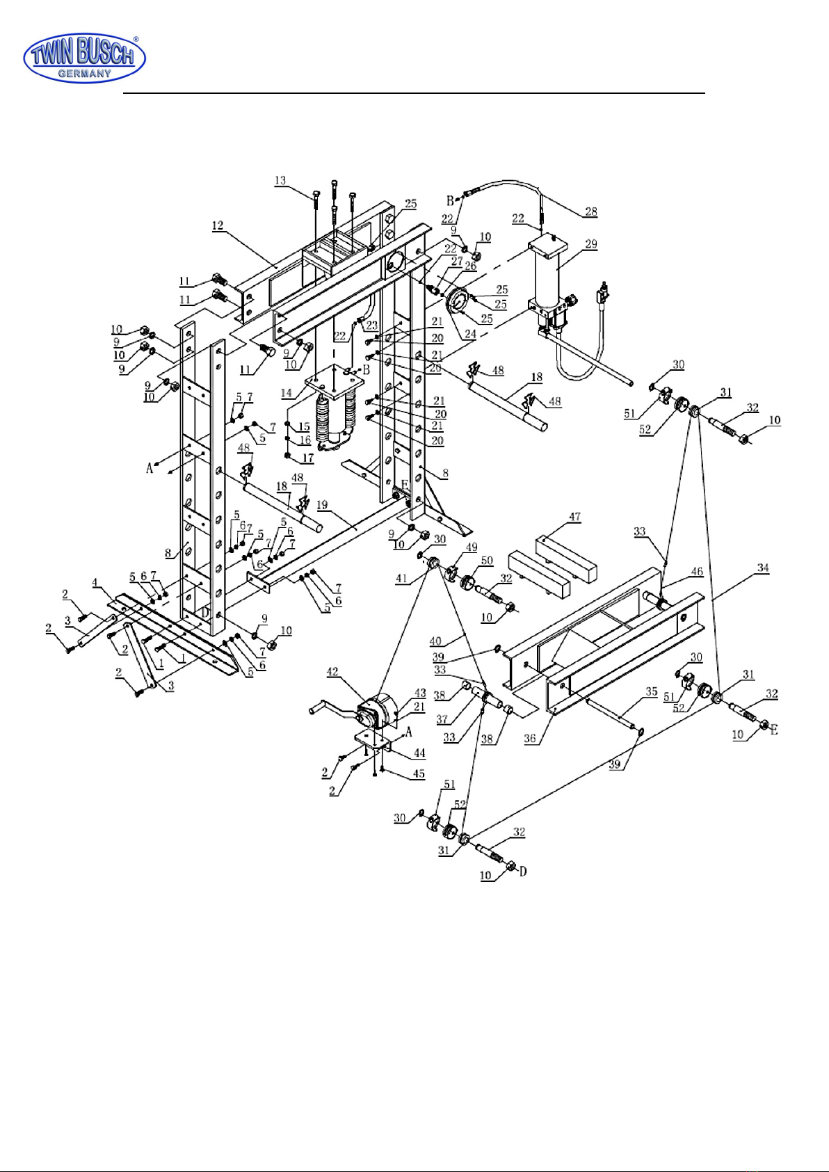
5. Spare parts 6
6. CE-certificate 11
Operation Manual
1. Important Information
1.1 Safety Information
1.1.1 Hazard Symbols Used in the Manuals
This manual includes the hazard symbols defined below when the operations or
maintenance job involves a potential danger. These symbols describe the level of danger
involved in performing a job on the tool and the precautions to take to avoid the hazard.
1.1.2 Safety Requirements
Important
Make sure to read, understand, and strictly follow all safety related instructions before
operation or maintenance of this equipment.
Intended Users
This manual is to be made available to all persons who are required to install, configure or
service equipment described herein, or any other associated operation.
Application Area
The machinery described is intended for machinery production and assembling spare parts.
It is used to press, size, assemble, rivet small parts in process and not for other use.
Personnel
Installation, operation and maintenance of the equipment should be carried out by qualified
personnel. A qualified person is someone who is technically competent and familiar with
all safety information and established safety practices with the installation process,
operation and maintenance of this equipment; and with all the hazards involved.