manuals.online logo
Brands
  1. Home
  2. •
  3. Brands
  4. •
  5. Tyco Electronics
  6. •
  7. Industrial Equipment
  8. •
  9. Tyco Electronics AMP-O-LECTRIC 690675-2 User manual

Tyco Electronics AMP-O-LECTRIC 690675-2 User manual

Instruction Sheet
AMP-O-LECTRIC* Terminatin Machine
Conversion Kits 690675-2 and 692613-1 408-8022
LOC B
1
of 4
E
2009 Tyco Electronics Corporation, Harrisburg, PA
All International Rights Reserved
TE logo and Tyco Electronics are trademarks.
*Trademark. Other products, logos, and company names used are the property of their respective owners.
TOOLING ASSISTANCE CENTER 1-800-722-1111
PROD CT INFORMATION 1-800-522-6752 This controlled document is subject to change.
For latest revision and Regional Customer Service,
visit our website at
www.tycoelectronics.com
06 FEB 09 Rev A
for Miniature Quick-Chan e Applicators
ITEM NO. PART NO. DESCRIPTION QTY
1 690671–1 PLATE, Base 1
2 690672–2 MOUNT, Base 1
3 4–21002–4 SCREW, Btn Hd Cap, 3/8–16 x .500 in. L 3
4 3–21000–6 SCREW, Skt Hd Cap, No. 10–32 x .625 in. L 2
5 690673–2 BRACKET, Hold–Down 1
6 2–21000–7 SCREW, Skt Hd Cap, No. 8–32 x .500 in. L 2
7 690674–1 STOP, Rear 2
8 21009–4 SETSCREW, Skt, Slflkg, 1/4–20 x .375 in. L 1
9 690499–1 RAM 1
10 –– Deleted ––
11 694925–1* BRACKET ASSY, Vertical Reel REF
12 694928–2 BRACKET, LH Stock Guide 1
13 470268–1 GUIDE, Stock 1
14 3–21000–1 SCREW, Skt Hd Cap, No. 8–32 x 1.00 in. L 4
15 27708–3 KNOB, Thumbscrew 2
16 21022–2 NUT, Slflkg, No. 8–32 1
17 455744–1 SHROUD, End Feed 1
18 455745–1 GUARD, End Feed 1
19 1–21899–3 WASHER, Flat, No. 8 12
20 21018–6 NUT, Hex, No. 8–32 7
21 7–22468–0 SCREW, Bdg Hd, No. 8–32 x .375 in. L 5
22 7–22468–3 SCREW, Bdg Hd, No. 8–32 x .750 in. L 1
23 22280–1 SPRING, Compression 1
24 455748–1 SHROUD, Side Feed 1
25 455749–1 GUARD, Side Feed 1
26 3–21002–4 SCREW, Btn Hd Cap, 1/4–20 x .625 in. L 1
27 21899–3 WASHER, Flat, 1/4 in. 1
*Refer to Customer Manual 409–5128 for the detailed parts breakdown of assembly and related parts..
Figure 1
408-8022
Conversion Kits 690675-2 nd 692613-1
Rev
A2
of 4 Tyco Electronics Corporation
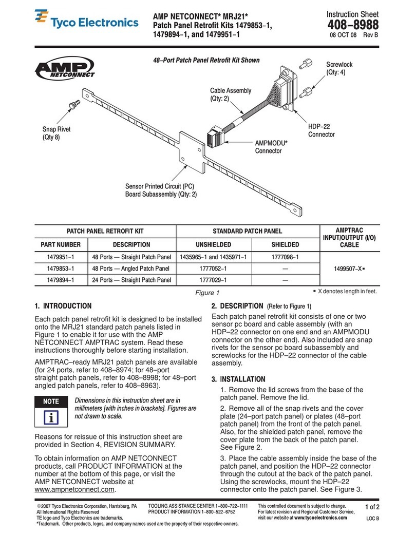
1. INTRODUCTION
These conversion kits are used to modify
AMP–O–LECTRIC Model K Terminating Machines to
accept miniature quick–change applicators. Kit No.
690675–2 is required for all end–feed and those
side–feed applicators that receive the strip terminals
in a horizontal position. Refer to the exploded view
and parts list in Figure 1 to make sure you have all
the parts required for the conversion. Kit No.
690675–2 plus Kit No. 692613–1 are required for
those side–feed applicators that receive the strip
terminals in a vertical position.
Throughout th s instructions, wh r r f r nc is
mad to hand-cycling th machin and to th
basic machin parts and ass mbli s, r f r to
Custom r Manual 409-5128.
Read the following instructions carefully before and
during the installation of the conversion kits on the
machine.
2. INSTALLATION OF CONVERSION KITS
Before starting installation of the conversion kits,
remove and store mechanical feed arm or air feed
operation arm from feed mechanism shaft by
loosening or removing clamp screws.
During installation of th conv rsion kit, c rtain
parts and ass mbli s MUST b r mov d and
ith r plac d in storag or r tain d for installation
of th kit. This kit is not r comm nd d for Mod ls
C, J, and J/K machin s.
MAKE CERTAIN that l ctrical pow r to th
machin is OFF by pulling th plug from th
r c ptacl .
2.1. Kit No. 690675-2 Inst ll tion
(Figure 2)
For installation of this kit, the machine must be
equipped with the proper vertical reel bracket
assembly (Part No. 694925–1). For information
pertaining to this assembly, refer to Customer Manual
409–5128.
1. The left–hand stock guide is required ONLY
when using side–feed applicators. With guide
installed on the bracket, attach the bracket to the
vertical reel bracket assembly with two screws
capped with knurled knobs, as shown.
2. To guide the terminal strip properly into
end–feed applicators, it is necessary that the
right–hand stock guide bracket be lowered by
using the UPPER hold in the vertical support for
the left screw, as shown.
3. Remove the two base mount screws and
washers form frame and install the base mount
supplied in the kit. Adjust height of the base mount
as low as possible in accordance with the machine
manual.
4. Hand–cycle in accordance with the machine
manual until the toggle link is at its lowest position.
5. Remove the arm retaining plate by removing the
four screws.
6. Loosen the setscrew in the ram, and then pivot
the toggle link toward the front of the machine and
slide out the toggle link pin to remove the ram.
7. Lubricate the four sides of the new ram,
supplied in the kit, as specified in the machine
manual.
8. Pivot the toggle link forward and install the new
ram with the toggle link pin removed in Step 6.
Pivot the ram back into position and tighten the
setscrew provided in the kit.
9. Install the ram retaining plate with the four
screws removed in Step 6.
10. Hand–cycle the machine to the rest position
(top dead center).
11. All parts removed for conversion, and any
unused parts of the kit, should be retained and
stored.
2.2. Kit No. 692613-1 Inst ll tion
(Figure 3)
This kit, in addition to Kit 690675–2, is required ONLY
for side feed applicators that receive strip terminals in
a vertical position.
1. Lay out the machine frame for holes as shown
in Figure 3.
2. Drill two size “G” holes, and thread with 5/16–18
UNC–2B tap.
3. Assemble the reel support as shown and install
on the machine with the two screws supplied in the
kit.
3. INSTALLATION OF THE APPLICATOR FEED CAM
it is NECESSARY for all miniature quick–change
applicators, when used in an AMP–O–LECTRIC
machine, to be equipped with the CORRECT feed
cam as listed on the applicator parts list (log) supplied
with the applicator. CHECK the feed cam, and if
necessary, replace it as described in the applicator
instructions supplied with the applicator. Retain all
parts that are removed.
NOTE
i
NOTE
i
CAUTION
!
408-8022
Conversion Kits 690675-2 and 692613-1
3
of 4Rev
A
Tyco E ectronics Corporation
Figure 2
TYPICAL SHROUD AND
GUARD ASSEMBLY
(End Feed Shown)
SCREW
(Ref)
(Ref)
(REFER TO 409–5128)
NOTE
i
SEE FIGURE 3 FOR DRILLING OF FRAME AND
INSTALLATION OF REEL BRACKET ASSEMBLY
FOR KIT NO. 692613–1.
408-8022
Conversion Kits 690675-2 nd 692613-1
Rev
A4
of 4 Tyco Electronics Corporation
Figure 3
4. INSTALLATION AND REMOVAL OF
MINIATURE APPLICATOR
MAKE CERTAIN that electrical power to the
machine is OFF b pulling the plug from the
receptacle.
1. Install the movable stop on the back of the base
mount for the end feed applicator or on the left end
for the side feed applicator, as shown in Figure 2.
2. Place the applicator on the base mount, insert
the ram post in the machine ram, then slide the
applicator into position against the stops.
3. Secure the applicator with the hold–down
bracket and two screws supplied in the kit. The
location of the hold–down bracket differs for end
feed and side feed applicators. Make certain the
bracket is located correctly.
4. Load the applicator in accordance with the
applicator instruction sheet supplied with the
applicator.
5. Set the wire disc and insulation disc for the wire
gage to be used in accordance with the data plate
on the applicator and/or the applicator parts list
supplied with the applicator.
6. Adjust the base mount for the correct crimp
height in accordance with the machine manual.
7. Install the side feed or end feed shroud and
guard assembly, for the type of applicator installed,
as shown in Figure 2.
8. To remove the applicator from the machine,
unload the applicator tooling according to the
instruction sheet shipped with the applicator,
remove the hold–down bracket, and slide the
applicator away from the stops on the base mount
until the ram post is clear of the machine ram.
5. REVISION SUMMARY
Revisions to this instruction sheet include:
S
Updated document to current requirements
S
New format
CAUTION
!

This manual suits for next models

1

Other Tyco Electronics Industrial Equipment manuals

Tyco Electronics AMP NETCONNECT MRJ21 User manual

Tyco Electronics

Tyco Electronics AMP NETCONNECT MRJ21 User manual

Tyco Electronics KILOVAC EV200 Series User manual

Tyco Electronics

Tyco Electronics KILOVAC EV200 Series User manual

Tyco Electronics AMP 58246–1 User manual

Tyco Electronics

Tyco Electronics AMP 58246–1 User manual

Tyco Electronics AMP-TAPETRONIC 69875 Reference guide

Tyco Electronics

Tyco Electronics AMP-TAPETRONIC 69875 Reference guide

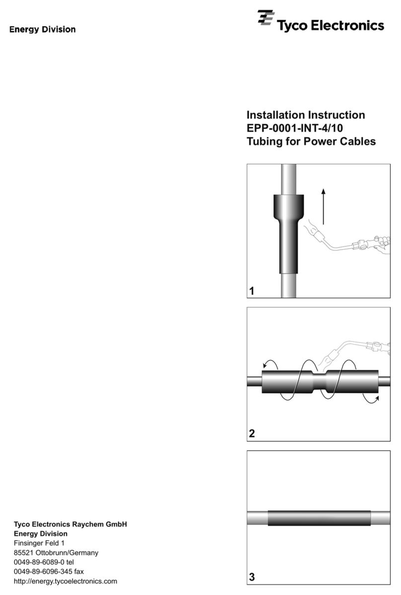
Tyco Electronics FOSC-600 C User manual

Tyco Electronics

Tyco Electronics FOSC-600 C User manual

Tyco Electronics 1752786-1 User manual

Tyco Electronics

Tyco Electronics 1752786-1 User manual

Tyco Electronics CS 200 Reference guide

Tyco Electronics

Tyco Electronics CS 200 Reference guide

Tyco Electronics DT-3000 Reference guide

Tyco Electronics

Tyco Electronics DT-3000 Reference guide

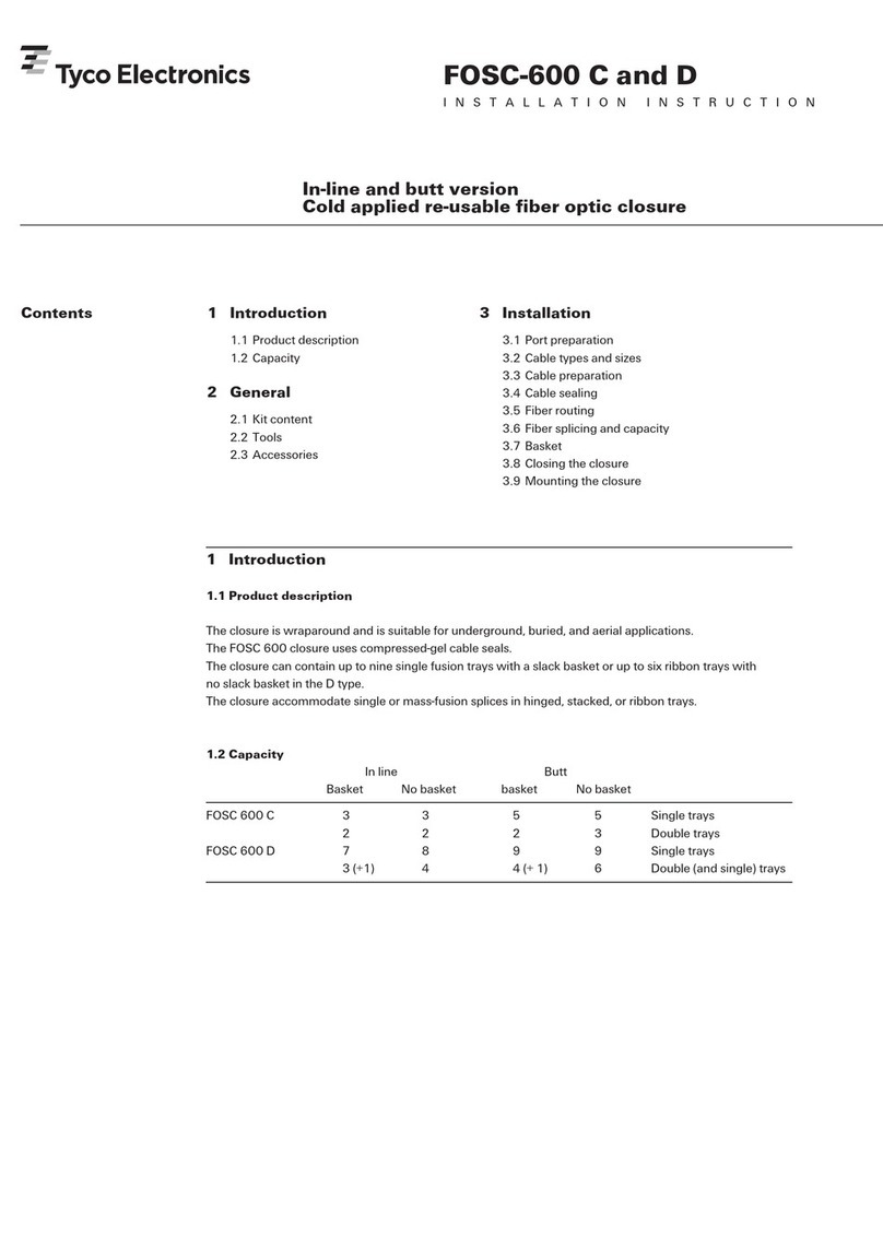
Tyco Electronics EPP-0001-INT-4/10 User manual

Tyco Electronics

Tyco Electronics EPP-0001-INT-4/10 User manual

Popular Industrial Equipment manuals by other brands

ABB HT610537 Operation manual

ABB

ABB HT610537 Operation manual

paladin FFC LAF5412 Operator and parts manual

paladin

paladin FFC LAF5412 Operator and parts manual

Lamtec 662R2127 Operatoring Instructions

Lamtec

Lamtec 662R2127 Operatoring Instructions

Tuchel Big instruction manual

Tuchel

Tuchel Big instruction manual

ABB HT613191 Operation manual

ABB

ABB HT613191 Operation manual

ABB HT611390 Operation manual

ABB

ABB HT611390 Operation manual

Nexen AIR CHAMP FC-605 user manual

Nexen

Nexen AIR CHAMP FC-605 user manual

RIDGID 141 Operator's manual

RIDGID

RIDGID 141 Operator's manual

Emerson AVENTICS NL1 operating instructions

Emerson

Emerson AVENTICS NL1 operating instructions

Buchi Lyovapor L-200 Pro Operation manual

Buchi

Buchi Lyovapor L-200 Pro Operation manual

dymax BlueWave MX-250 user guide

dymax

dymax BlueWave MX-250 user guide

SMC Networks CM2Y-Z Series Operation manual

SMC Networks

SMC Networks CM2Y-Z Series Operation manual

NTN K-S05 Series instruction manual

NTN

NTN K-S05 Series instruction manual

Extreme Networks XEM XTR Operation manual

Extreme Networks

Extreme Networks XEM XTR Operation manual

Napa Carlyle Tools 791-7125A operating manual

Napa

Napa Carlyle Tools 791-7125A operating manual

DANA DT Series Assembly instructions

DANA

DANA DT Series Assembly instructions

Index G200.3 operating instructions

Index

Index G200.3 operating instructions

Stahl SolConeX 8571/22 Series operating instructions

Stahl

Stahl SolConeX 8571/22 Series operating instructions

manuals.online logo
manuals.online logoBrands
  • About & Mission
  • Contact us
  • Privacy Policy
  • Terms and Conditions

Copyright 2025 Manuals.Online. All Rights Reserved.