manuals.online logo
Brands
  1. Home
  2. •
  3. Brands
  4. •
  5. Tyco Fire Product
  6. •
  7. Irrigation System
  8. •
  9. Tyco Fire Product CENTRAL H-1 User manual

Tyco Fire Product CENTRAL H-1 User manual

Product
Description
No. 5-4.0
1-98
The Model H-1 Dry Horizontal
Sidewall Sprinklers allow the
installation of sprinklers in areas
subject to freezing while being supplied
from a wet pipe sprinkler system. The
adjustable version uses a special cast
iron fitting. The primary advantage of
the adjustable version is the 21⁄2"(63.5
mm) of field adjustment. This is
provided by the unique feature of a
special elbow that allows more
adjustment than ever before. This
ensures perfect fit to the wall as the
sprinkler can easily be adjusted after
the outside face of the wall is installed.
Because the H-1 Dry Horizontal
Sidewall is allowed with NFPA 13
spacings for sidewall sprinklers in
either light or ordinary hazard, it can
throw considerably further than the
alternative method suggested in NFPA
13 of a dry pendent sprinkler on a 45°
angle.
The escutcheon assembly is com-
prised of a support piece permanently
attached to the sprinkler frame. The
wall escutcheon plate has 1⁄4" (6.4 mm)
of field adjustment and can be installed
after the sprinkler.
Therefore, the total field adjustment
for the Model H-1 Adjustable Dry
Sidewall Sprinkler is 23⁄4" (69.9 mm).
The Model H-1 is Listed by U.L. and
U.L.C. for use as a standard sprinkler
that qualifies for installation in accor-
dance with current NFPA 13 Standards.
Operation: A fusible alloy is sealed
into a bronze center strut by a stainless
steel ball. When the alloy melts at its
rated temperature, the ball is forced
H-1 Dry Sidewall
Model H-1
Adjustable
Dry Sidewall
Automatic Sprinkler
Manufactured by: Central Sprinkler Company
451 North Cannon Avenue, Lansdale, Pennsylvania 19446
upward into the center strut
releasing the two ejectors and
operating the sprinkler.
1⁄2" (15 mm) Orifice
Dry Sidewall
Automatic
Sprinklers
Model: H-1
Style: DrySidewall
(adjustableor
non-adjustable)
Wrench: H-1(Part#1090) For adjust-
mentofsprinkler only. See
installationsequenceSteps#2
and#4onpage3.
Orifice Size: 1⁄2"
(15 mm)
K-Factor: See“OrderingRangeChart”
on page two.
Thread Size: 1"
(25 mm)
NPT
TemperatureRating &FrameArmColor:
135°F/57°C:
(*leadonly)
165°F/74°C:
(*wax,lead,wax-over-lead)
212°F/100°C:
(*wax,lead,wax-over-lead)
286°F/141°C:
(*wax,lead,wax-over-
lead,Listedashightemperature,wax
coatedforinstallationwheremaximum
ambientceilingtemperaturedoesnot
exceed150
°
F.)
* Wax,lead andwax-over-leadare
U.L.Listedonly.
Approvals: U.L.,U.L.C.
M.E.A.(375-75-SA)
MaximumWorkingPressure: 175psi
(12.1bar)
FactoryHydroTest: 100%at500psi
(34.5bar)
StandardFinishes: brass,chrome plated
Escutcheon:brass,chromeplatedand
white painted with
additional special finishes
available upon request
HighestAllowableAmbientStorage
Temperature:100°F/38°C
Technical
Data
OBSOLETE
2
1. For the adjustable version, order by “C” dimension shown (in 11⁄4" (31.8 mm) increments).
Minimum “C” dimension is 61⁄4" (158.8 mm). Field adjustment is ±13⁄8" (34.9 mm).
2. Do not overtighten special cast iron fitting into the branchline fitting or breakage may result.
3. Approved length limitation is 36" (914.4 mm).
4. K-factor reduces by .03 per each 11⁄4" (31.8 mm) additional length.
5. Install by applying pipe wrench to 1" (25.4 mm) brass connector, not to the sprinkler itself.
211⁄4" (539.8 mm) 4.96
221⁄2" (571.5 mm) 4.93
233⁄4" (603.3 mm) 4.90
25" (635.0 mm) 4.87
261⁄4" (666.8 mm) 4.84
271⁄2" (698.5 mm) 4.81
283⁄4" (730.3 mm) 4.78
30" (762.0 mm) 4.75
311⁄4" (793.8 mm) 4.72
321⁄2" (825.5 mm) 4.69
333⁄4" (857.3 mm) 4.66
35" (889.0 mm) 4.63
H-1 Adjustable Ordering Chart and
K-Factor Table
Order “C”
Dim. K-Factor
Figure 1
Model H-1 Adjustable Dry Sidewall
1 15/16" (49.2 mm) Min.
2 3/16" (55.6 mm) Max.
Sprinkler
Branch Line
"C" Dimension
(Min = 6
1
/
4
" (158.8 mm))
Main Tube
1" (25 mm) NPT
Finished Wall
Finished
Ceiling
Escutcheon
3 3/16"
(81.0 mm)
Dia.
4" (101.6 mm)
Min.
6" (152.4 mm)
Max.
1" (25.4 mm), 1 1/4" (31.8 mm),
1 1/2" (38.1 mm) Line Fittng = 3"
2" (50.8 mm) Line Fitting =
3 1/2" (88.9 mm)
1/2"
(12.7 mm)
2 9/16"
(65.1 mm)
21/4" (57.2 mm)
Diameter
(minimum)
Order “C”
Dim. K-Factor
61⁄4" (158.8 mm) 5.32
71⁄2" (190.5 mm) 5.29
83⁄4" (222.3 mm) 5.26
10" (254.0 mm) 5.23
111⁄4" (285.8 mm) 5.20
121⁄2" (317.5 mm) 5.17
133⁄4" (349.3 mm) 5.14
15" (381.0 mm) 5.11
161⁄4" (412.8 mm) 5.08
171⁄2" (444.5 mm) 5.05
183⁄4" (476.3 mm) 5.02
20" (508.0 mm) 4.99
Caution: This unit must only be installed with the special
cast iron fitting supplied, as this a listed assembly.
Installation into any other fitting will void the listing.
OBSOLETE
3
ensure that neither accumulate within
the sprinkler.
Special care must be taken when
installing with a copper system.
Sprinklers must be installed only after
the inside of the sprinkler drop and
associated fittings have been wire
brushed to remove any flux. Residual
flux can cause corrosion and in
extreme cases can impair proper
sprinkler operation.
Design Requirements—Standard Applications
The Model H-1 Dry Sidewall Sprinklers are intended for standard area
coverages and standard flow and pressure requirements as specified in
current NFPA 13 Standards for both ordinary and light hazard.
Design
Data
Installation
All Model H-1 Dry Sidewall Auto-
matic Sprinklers must be installed
according to current NFPA 13 Stan-
dards.
Dry sprinklers are designed to
prevent water from accumulating in
drops to sprinklers. To accomplish
this, they have a fitting that protrudes
into the branch line that allows the
plug to sit above the water line, if
there is any residual water, and
operate without the potential of
freezing.
Deviations from these require-
ments and standards or any alteration
to the sprinkler itself will void any
warranty made by Central Sprinkler
Company. In addition, installation
must also meet local government
provisions, codes and standards as
applicable.
For standard applications the
system piping may be hydraulically
calculated or pipe-scheduled. Check
for the proper model, style, orifice
size, and temperature rating prior to
installation. Install sprinklers after the
piping is in place to avoid mechanical
damage; replace any damaged units.
Wet pipe systems must be protected
from freezing.
Upon completion of the installation,
the system must be tested per
recognized standards.
In the event of a thread leak,
remove the unit, apply new pipe joint
compound or tape, and reinstall.
Installation Sequence
Step 1. The unit must be installed in
a sidewall position.
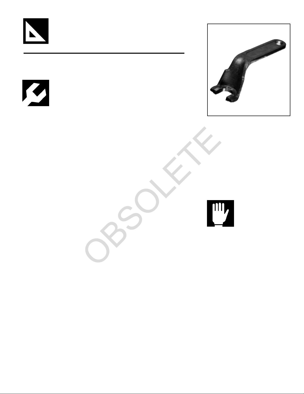
H-1 Sprinkler Wrench (Part #1090)
Step 2. The special cast iron fitting is
not attached to the sprinkler assem-
bly in the factory as this fitting must
be made into the sprinkler line fitting
first. Warning: Do not over-tighten
special cast iron fitting into the
branch line fitting or breakage will
result. The sprinkler assembly is
attached to the special cast iron fitting
by screwing the threaded connector
tightly. This is done by using a pipe
wrench on the threaded connector.
Never wrench on the sprinkler head
itself for tightening the threaded
connector into the special cast iron
fitting. The Model 1090 sprinkler
wrench may be used on the sprinkler
for adjustment purposes only (see
Step #4).
Step 3. Use only a non-hardening
pipe joint compound or Teflon* tape.
Apply only to the male threads.
*Teflon is a trademark of the DuPont Corp.
Step 4. Adjustment in length is
obtained by applying the sprinkler
head wrench and turning either
clockwise or counterclockwise. Note
that no locking is required when the
sprinkler is in its desired position.
Step 5. To install the escutcheon
plate, align it with and push it over the
sprinkler body and into the upper
support piece until the outer edge of
the escutcheon meets the mounting
surface.
Do not over- or under-tighten the
sprinkler to compensate for inaccu-
rate escutcheon plate adjustment.
Caution: Special care must be taken
when installing with a CPVC system.
Sprinklers must be installed after the
manufacturer's recommended setting
time for the primer and cement to
Care &
Maintenance
Sprinklers must be handled care-
fully. They must not be transported
or stored where ambient temperature
may exceed 100°F/38°C. For best
results, store them in a dry, cool
location in the original shipping
package.
Do not install sprinklers that have
been dropped or visibly damaged.
Sprinklers should never be painted,
coated, plated or altered in any other
way from manufactured condition or
they may not function properly. Any
sprinklers altered in such a manner
must be replaced.
The owner is responsible for the
proper operating condition of all fire
protection devices and accessories.
The NFPA standard 25 entitled,
“Inspection, Testing and Maintenance
of Water-Based Fire Protection
OBSOLETE
©1997 Central Sprinkler Company
Printed in U.S.A. H-1Adj.3
Ordering Information: When
placing an order, indicate the full
product name. Please specify the
quantity, model, style, orifice size,
temperature rating, sprinkler finish, and
escutcheon finish, and required “C”
Dimension. “C” Dimensions are listed
in 11⁄4" (31.8 mm) increments. (See
Ordering Range Chart on Page 3).
Availability and Service: Central
sprinklers, valves, accessories and
other products are available through-
out the U.S. and Canada, and interna-
tionally, through a network of Central
Sprinkler distribution centers. You
may write directly to Central Sprinkler
Company, or call (215) 362-0700 for
the distributor nearest you.
Patents: Patents are pending.
Conversion Table:
1 inch = 25.400 mm
1 foot = 0.3048 M
1 pound = 0.4536 kg
1 foot pound = 1.36 Nm
1 psi = 6.895 kpa
= 0.0689 bar
= 0.0703 kg/cm2
1 U.S. gallon = 3.785 dm3
= 3.785 liters
Conversions are approximate.
Ordering
Information
Central Sprinkler Company
451 N. Cannon Avenue, Lansdale, PA 19446
Phone (215) 362-0700
FAX (215) 362-5385
Systems”
, contains guidelines and
minimum maintenance requirements.
Furthermore, the local
Authority
Having Jurisdiction
may have addi-
tional regulations and requirements
for maintenance, testing, and inspec-
tion that must be obeyed.
It is advisable to have sprinkler
systems inspected regularly by a
qualified inspection service. Length
of time between such inspections can
vary due to accessibility, ambient
atmosphere, water supply, and site
activity.
Do not attempt to reassemble or
otherwise reuse a sprinkler that has
operated. Replace any sprinkler
exhibiting corrosion or damage;
always use new sprinklers of the
same orifice, style, and temperature
rating as replacements.
Because the discharge pattern is
critical to protection of life and
property, nothing should be hung or
attached to the sprinkler unit that
would disrupt the pattern. Such
obstructions must be removed. In the
event that construction has altered
the original configuration, additional
sprinklers should be installed to
maintain the protection level.
Do not attempt to replace sprinklers
without first removing the fire protec-
tion system from service. Be certain
to secure permission from all
Authori-
ties Having Jurisdiction
, and notify all
personnel who may be affected
during system shutdown. A fire
watch during maintenance periods is
a recommended precaution.
To remove the system from service,
first refer to the system operating
guide and valve instruction. Drain
water and relieve pressure in the
pipes. Remove the existing unit and
install the replacement, using only the
recommended sprinkler wrench. Be
certain to match model, style, orifice,
and temperature rating.
A fire protection system that has
been shut off after an activation
should be repaired and returned to
service immediately. Inspect the
entire system for damage and replace
or repair as necessary. Sprinklers
that did not operate but were sub-
jected to corrosive elements of
combustion or excessive tempera-
tures should be inspected, and
replaced if need be. The
Authority
Having Jurisdiction
will detail mini-
mum replacement requirements and
regulations.
Guarantee: Central Sprinkler
Company will repair and/or replace
any products found to be defective in
material or workmanship within a
period of one year from the date of
shipment. Please refer to the current
Price List for further details of the
warranty.
OBSOLETE

Other Tyco Fire Product Irrigation System manuals

Tyco Fire Product Star Pulsar S195 User manual

Tyco Fire Product

Tyco Fire Product Star Pulsar S195 User manual

Tyco Fire Product Star Quasar Q User manual

Tyco Fire Product

Tyco Fire Product Star Quasar Q User manual

Tyco Fire Product Gem F978 User manual

Tyco Fire Product

Tyco Fire Product Gem F978 User manual

Tyco Fire Product CENTRAL BV4-QREC User manual

Tyco Fire Product

Tyco Fire Product CENTRAL BV4-QREC User manual

Tyco Fire Product TY-QRF User manual

Tyco Fire Product

Tyco Fire Product TY-QRF User manual

Tyco Fire Product central bvr User manual

Tyco Fire Product

Tyco Fire Product central bvr User manual

Tyco Fire Product Gem FR-1 User manual

Tyco Fire Product

Tyco Fire Product Gem FR-1 User manual

Tyco Fire Product CENTRAL Attic User manual

Tyco Fire Product

Tyco Fire Product CENTRAL Attic User manual

Tyco Fire Product CENTRAL ESFR-25 User manual

Tyco Fire Product

Tyco Fire Product CENTRAL ESFR-25 User manual

Tyco Fire Product TY-B Series User manual

Tyco Fire Product

Tyco Fire Product TY-B Series User manual

Tyco Fire Product Star StarMax S100 User manual

Tyco Fire Product

Tyco Fire Product Star StarMax S100 User manual

Tyco Fire Product CENTRAL WS User manual

Tyco Fire Product

Tyco Fire Product CENTRAL WS User manual

Tyco Fire Product CENTRAL B User manual

Tyco Fire Product

Tyco Fire Product CENTRAL B User manual

Tyco Fire Product Star S190 User manual

Tyco Fire Product

Tyco Fire Product Star S190 User manual

Tyco Fire Product CENTRAL GB-20 User manual

Tyco Fire Product

Tyco Fire Product CENTRAL GB-20 User manual

Tyco Fire Product CENTRAL H User manual

Tyco Fire Product

Tyco Fire Product CENTRAL H User manual

Tyco Fire Product Gem ISSUE D QUARTZOID User manual

Tyco Fire Product

Tyco Fire Product Gem ISSUE D QUARTZOID User manual

Tyco Fire Product Gem F685 User manual

Tyco Fire Product

Tyco Fire Product Gem F685 User manual

Tyco Fire Product Gem FR-1 User manual

Tyco Fire Product

Tyco Fire Product Gem FR-1 User manual

Tyco Fire Product Gem RFII Series User manual

Tyco Fire Product

Tyco Fire Product Gem RFII Series User manual

Tyco Fire Product CENTRAL ESFR-17 User manual

Tyco Fire Product

Tyco Fire Product CENTRAL ESFR-17 User manual

Tyco Fire Product TY300-FRB User manual

Tyco Fire Product

Tyco Fire Product TY300-FRB User manual

Tyco Fire Product Star Galaxy SG User manual

Tyco Fire Product

Tyco Fire Product Star Galaxy SG User manual

Tyco Fire Product CENTRAL H17/32 User manual

Tyco Fire Product

Tyco Fire Product CENTRAL H17/32 User manual

Popular Irrigation System manuals by other brands

Gardena 1254 operating instructions

Gardena

Gardena 1254 operating instructions

claber 8063 manual

claber

claber 8063 manual

NeilMed Hydro Pulse HP-100 User instructions

NeilMed

NeilMed Hydro Pulse HP-100 User instructions

Reliable F1FR56-300 QREC Series manual

Reliable

Reliable F1FR56-300 QREC Series manual

Valley VRI-iS installation manual

Valley

Valley VRI-iS installation manual

Underhill Mirage M-125 Operating and maintenance instructions

Underhill

Underhill Mirage M-125 Operating and maintenance instructions

JARDIBRIC BL-PNR Quick installation guide

JARDIBRIC

JARDIBRIC BL-PNR Quick installation guide

Tyco DS-1 Series manual

Tyco

Tyco DS-1 Series manual

Reliable F1S5 Series Bulletin

Reliable

Reliable F1S5 Series Bulletin

Cadman 6003 OPERATOR'S PARTS and MAINTENANCE MANUAL

Cadman

Cadman 6003 OPERATOR'S PARTS and MAINTENANCE MANUAL

Viking VK482 quick start guide

Viking

Viking VK482 quick start guide

Johnson Controls tyco TY-B Series manual

Johnson Controls

Johnson Controls tyco TY-B Series manual

RainMaster RME EAGLE user manual

RainMaster

RainMaster RME EAGLE user manual

AQUAJOE AJ-OMS18-TRB user manual

AQUAJOE

AQUAJOE AJ-OMS18-TRB user manual

AQUAJOE AJ-ISSS-RM manual

AQUAJOE

AQUAJOE AJ-ISSS-RM manual

Tyco D4a manual

Tyco

Tyco D4a manual

Johnson Controls tyco TY-FRB Series manual

Johnson Controls

Johnson Controls tyco TY-FRB Series manual

Irritrol SIS 120P Series Maintenance and operating instructions

Irritrol

Irritrol SIS 120P Series Maintenance and operating instructions

manuals.online logo
manuals.online logoBrands
  • About & Mission
  • Contact us
  • Privacy Policy
  • Terms and Conditions

Copyright 2025 Manuals.Online. All Rights Reserved.