manuals.online logo
Brands
  1. Home
  2. •
  3. Brands
  4. •
  5. Tyco Fire Product
  6. •
  7. Irrigation System
  8. •
  9. Tyco Fire Product CENTRAL BV4-QREC User manual

Tyco Fire Product CENTRAL BV4-QREC User manual

Disposable Protection Cap. The
Protective Cap is temporarily removed
to install the BV4-QREC, and then
replaced to protect the BV4-QREC
while the ceiling is being installed and
finished. The tip of the Protection Cap
can be used to mark the center of the
ceiling hole into plaster board, ceiling
tiles, etc. by pushing the ceiling
product against the Protection Cap.
When the ceiling installation is
complete, the Protection Cap is
removed and the Cover Plate Assem-
bly installed.
Operation: When exposed to heat
from a fire, the Cover Plate, which is
soldered to the Retainer Assembly at
three points, falls away to expose the
Sprinkler Assembly. At this point the
Deflector supported by the Arms
drops down to its operational position.
The glass bulb contains a fluid which
expands when exposed to heat. When
the rated temperature is reached, the
fluid expands sufficiently to shatter the
glass bulb, which then allows the
sprinkler to activate & flow water.
WARNING
The Model BV4-QREC ECLH
Concealed Pendent Sprinklers
described herein must be installed &
maintained in compliance with this
document, as well as with the
applicable standards of the National
Fire Protection Association, in addition
to the standards of any other
authorities having jurisdiction. Failure
to do so may impair the integrity of
these devices.
The owner is responsible for
maintaining their fire protection
system and devices in proper
operating condition. The installing
contractor or sprinkler manufacturer
should be contacted relative to any
questions.
Tyco Fire Products --- www.centralsprinkler.com
451 North Cannon Avenue, Lansdale, Pennsylvania 19446 --- USA
Customer Service/Sales: Tel: (215) 362-0700 / Fax: (215) 362-5385
Technical Services: Tel: (800) 381-9312 / Fax: (800) 791-5500
Model BV4-QREC
5.6 K-factor
Quick Response
Extended Coverage Light Hazard
Concealed Pendent Glass Bulb Automatic Sprinklers
No. 2-8.0
General
Description
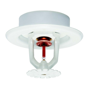
The Central Model BV4-QREC,
5.6 K-factor, Quick Response,
Extended Coverage Light Hazard
(ECLH) Concealed Pendent Sprin-
klers are decorative glass bulb
sprinklers designed for use in light
hazard occupancies such as
churches, hospitals, offices, and
restaurants.
They are intended for use in auto-
matic sprinkler systems designed in
accordance with standard installation
rules (e.g., NFPA 13) for the protec-
tion of light hazards up to a maximum
coverage area of 324 ft2(30,1 m2), as
compared to the maximum coverage
area of 225 ft2(20,9 m2) for standard
coverage sprinklers.
Each unit includes a Cover Plate
Assembly which conceals the sprin-
kler operating components above the
ceiling. The separable two-piece
design of the Cover Plate and Support
Cup Assemblies allows installation of
the sprinklers and pressure testing of
the fire protection system prior to
istallation of a suspended ceiling or
application of the finish coating to a
fixed ceiling. They also permit
removal of suspended ceiling panels
for access to building service equip-
ment without having to first shut down
the fire protection system and remove
sprinklers.
Also, the separable two-piece design
of the sprinkler provides for 1/2 inch
(12,7 mm) of vertical adjustment, to
reduce the accuracy to which the
length of fixed pipe drops to the
sprinkler must be cut.
The BV4-QREC ECLH Concealed
Pendent Sprinkler is shipped with a
Technical
Data
CENTRAL BV4-QREC 2-01
Extended
Coverage Light
Hazard
Concealed
Pendent
Sprinklers
Sprinkler Identification Number
SIN C3532
Approvals
UL and C-UL Listed. NYC Approved.
(Refer to Table 1. The approvals apply
only to the service conditions indicated
in the Design Criteria Section)
Maximum Working Pressure
175 psi (12,1 bar)
Pipe Thread Connection
1/2 inch NPT
Discharge Coefficient
K = 5.6 GPM/psi1/2 (80,6 LPM/bar1/2)
Temperature Ratings
155°F/68°C Sprinkler - 135°F/57°C Plate
200°F/93°C Sprinkler - 165°F/74°C Plate
Continued on Page 2
OBSOLETE
(63,5 mm ±3,2 mm)
Hole Diameter
3-1/4" (82,6 mm)
Diameter 3/16"
(4,8mm)
2-1/2" ±1/8"
2" 1/4"
(50,8 mm 6,4 mm)
±±
WRENCH
FLAT
ELEVATION VIEW
CENTRAL
3/16" (4,8 mm) Minimum
11/16" (17,5 mm) Maximum
ELEVATION VIEW
CENTRAL
COVER PLATE
ASSEMBLY
COVER PLATE
SUPPORT CUP
DEFLECTOR
ARMS
GLASS BULB
OPERATING
ELEMENT
GASKETED
SPRING PLATE
(BELLEVILLE SEAL)
RETAINER
ASSEMBLY
FRAME
Figure 2 - Model BV4-QREC, ECLH
Concealed Pendent Sprinkler (Activated)
Figure 1 - Model BV4-QREC,
ECLH Concealed Pendent Sprinkler
Figure 3 - Cross Section Model BV4-QREC,
ECLH Concealed Pendent Sprinkler Figure 4 - BV4 Sprinkler Wrench
(Part #1075)
Technical
Data (Cont.)
Finishes
Sprinkler: Natural Brass
Cover Plate: Chrome or Brass Plated; *Flat White, Bright
White, or Custom Painted
* Standard Finish supplied when White is specified
Physical Characteristics
The Model BV4-QREC ECLH Concealed Pendent Sprinklers
utilize a dezincification resistant (DZR) bronze frame and a 3 mm
bulb. The two-piece button assembly is brass and copper. The
sprinkler frame orifice is sealed with a gasketed spring plate
(Belleville Seal) consisting of a beryllium nickel disc spring that is
sealed on both its inside and outside edges with a TeflonTM gasket.
The arms and deflector are bronze, and the support cup is
steel. The cover plate and retainer assembly are brass.
OBSOLETE
Design
Criteria
The Model BV4-QREC ECLH Concealed Pendent Sprinklers are UL and C-ULlisted and NYC Approved (MEA 64-93-E Vol. II),
for use in light hazard occupancies, using the design criteria in Table 1 as well as any additional requirements specified in current NFPA
13 Standards for Extended Coverage Pendent Sprinklers.
The Model BV4-QREC ECLH Concealed Pendent Sprinklers are only listed with the Series BV4 Concealed Cover Plates.
The minimum lateral spacing between the BV4-QREC ECLH Concealed Pendent Sprinkers, to prevent cold soldering, is 8
feet (2,4 m).
The Support Cup of the Model BV4-QREC ECLH Concealed Pendent Sprinkler has several slots in the base of the cup
which allows heat from a fire to flow past the thermal sensitive operating element accelerating sprinkler activation. Due to
the presence of these slots, the installation of these sprinklers in ceilings which have positive pressure in the space above,
is not permitted.
Minimum
Spacing Flow/Pressure Temperature Rating
LH (0.1 gpm/sq. ft.)
16' x 16' 26.0 gpm / 21.6 psi 155°F/68°C Sprinkler - 135°F/57°C Plate
(4,9 m x 4,9 m)
98,4 Lpm / 1,49 bar
200°F/93°C Sprinkler - 165°F/74°C Plate
18' x 18' 33.0 gpm / 34.7 psi 155°F/68°C Sprinkler - 135°F/57°C Plate
(5,5 m x 5,5 m) 124,9 Lpm / 2,39 bar
200°F/93°C Sprinkler - 165°F/74°C Plate
Table 1 - UL and C-UL Listing Criteria for the Installation of Model BV4-QREC
Extended Coverage Light Hazard Concealed Pendent Sprinklers
Installation
The Model BV4-QREC ECLH Con-
cealed Pendent Sprinklers must be
installed in accordance with the
following instructions.
NOTES
Do not install any bulb type sprinkler if the
bulb is cracked or there is a loss of liquid
from the bulb. With the sprinkler held
horizontally, a small air bubble should be
present. The diameter of the air bubble is
approximately 1/16 inch (1,6 mm) for the
155
°
F/68
°
C to 3/32 inch (2,4 mm) for the
200
°
F/93
°
C rating.
A leak tight 1/2 inch NPT sprinkler joint
should be obtained with a torque of 7 to 14
ft.lbs. (9,5 to 19,0 Nm). A maximum of 21
ft.lbs. (28,5 Nm) of torque is to be used to
install 1/2 inch NPT sprinklers. Higher
levels of torque may distort the
sprinkler inlet with consequent
leakage or impairment of the sprinkler.
Do not attempt to make up for
insufficient adjustment in the escutch-
eon plate by under- or overtightening
the sprinkler. Readjust the position of
the sprinkler fitting to suit.
Step 1. The sprinkler must only be
installed only in the pendent position
and with the centerline of the sprinkler
perpendicular to the mounting
surface.
Step 2. Remove the Protective Cap.
Step 3. With pipe thread sealant
applied to the pipe threads, hand
tighten the sprinkler into the sprinkler
fitting.
Step 4. Wrench tighten the Sprinkler
using only the BV4 Sprinkler Wrench
(Ref. Figure 4). The BV4 Sprinkler
Wrench is to be applied to the
Sprinkler Wrench flats only.
Step 5. Replace the Protective Cap
by pushing it upwards until it bottoms
out against the Support Cup. The
Protective Cap helps prevent damage
to the Deflector and Arms during
ceiling installation and/or during
application of the finish coating of the
ceiling. It may also be used to locate
the center of the clearance holes by
gently pushing the ceiling material up
against the center point of the
Protective Cap.
NOTE
As Long as the Protective Cap
remains in place, the system is
considered to be "Out of Service"
Step 6. After the ceiling has been
completed with the 2-1/2 inch (66,7
mm) diameter clearance hole and in
preparation for installing the Cover
Assembly, remove and discard the
Protective Cap, and verify that the
Deflector moves up and down freely.
If the Sprinkler has been damaged
and the Deflector does not move up
and down freely, replace the entire
Sprinkler Assembly. Do not attempt
to modify or repair a damaged
sprinkler.
Step 7. Screw on the Cover Plate/
Retainer Assembly until its flange just
comes in contact with the ceiling. Do
not continue to screw on the Cover
Plate/Retainer Assembly such that it
lifts a ceiling panel out of its normal
position. If the Cover Plate/Retainer
Assembly cannot be engaged
sufficiently to contact the ceiling, the
sprinkler fitting must be repositioned.
OBSOLETE
Printed in U.S.A. 2-01
Ordering Information: When
placing an order, indicate the full
product name. Please specify the
quantity, model, style, orifice size,
temperature rating, type of finish or
coating, and sprinkler wrench. Refer
to price list for complete listing of Part
Numbers.
Patents: U.S.A. Patent Number
4,014,388 is applicable to the Model
BV4-QREC ECLH Concealed
Pendent Sprinklers. Other Patents
are pending with regard to other
design features.
Teflon is a trademark of the DuPont Corp.
Ordering
Information
Flow Control
Tyco Fire

Products
The Model BV4-QREC ECLH Concealed
Pendent Sprinklers must be maintained
and serviced in accordance with the
following instructions.
NOTES
Absence of the Cover Plates which is
used to cover a clearance hole, may delay
the time to operation in a fire situation.
When properly installed, there is a
nominal 3/32 inch (2,4 mm) air gap
between the lip of the Cover Plate and the
ceiling. This air gap is necessary for
proper operation of the sprinkler. If the
ceiling is to be repainted after the
installation of the sprinkler, care must be
exercised to ensure that the new paint
does NOT seal off any of the air gap.
Factory painted Cover Plates MUST NOT
be repainted. They should be replaced, if
necessary, by factory painted units.
Do not pull the Cover Plates relative to the
Retainer Assembly. Separation may
result.
Before closing a fire protection system
main control valve for maintenance work
on the fire protection system it controls,
permission to shut down the affected fire
protection systems must be obtained from
the proper authorities. All personnel who
may be affected by this action must be
notified.
Sprinklers which are found to be leaking
or exibiting visible signs of corrosion must
be replaced.
Automatic sprinklers must never be
shipped or stored where their tempera-
tures will exceed 100°F/38°C and they
must never be painted, plated, coated or
otherwise altered after leaving the factory.
Modified sprinklers must be replaced.
Sprinklers that have been exposed to
corrosive products of combustion, but
have not operated, should be replaced if
they cannot be completely cleaned by
wiping the sprinkler with a cloth or by
brushing it with a soft bristle brush.
Care must be exercised to avoid damage
- before, during, and after installation.
Sprinklers damaged by dropping, striking,
wrench twist/slippage, or the like, must be
replaced. Also, replace any sprinkler that
has a cracked bulb or that has lost liquid
from its bulb (Ref. Installation Section).
If a sprinkler must be removed for some
reason, do not reinstall it or a replacement
without reinstalling the Cover Plate
Assembly. If a Cover Plate Assembly
becomes dislodged during service,
replace it immediatly.
The owner is responsible for the inspec-
tion, testing, and maintenance of their fire
protection system and devices in
compliance with this document, as well as
with the applicable standards of the
National Fire Protection Association (e.g.,
Care &
Maintenance
NFPA 25), in addition to the standards of
any other authorities having jurisdiction.
The installing contractor or sprinkler
manufacturer should be contacted relative
to any questions.
It is recommended that automatic sprinkler
systems be inspected, tested, and
maintained by a qualified Inspection
Service.
Products manufactured by Tyco Fire
Products are warranted solely to the
original Buyer for ten (10) years against
defects in material and workmanship
when paid for and properly installed and
maintained under normal use and
service. This warranty will expire ten
(10) years from date of shipment by
Tyco Fire Products. No warranty is
given for products or components
manufactured by companies not
affiliated by ownership with Tyco Fire
Products or for products and compo-
nents which have been subject to
misuse, improper installation, corrosion,
or which have not been installed,
maintained, modified or repaired in
accordance with applicable Standards
of the National Fire Protection Associa-
tion, and/or the standards of any other
Authorities Having Jurisdiction. Materi-
als found by Tyco Fire Products to be
defective shall be either repaired or
replaced, at Tyco Fire Products' sole
option. Tyco Fire Products neither
assumes, nor authorizes any person to
assume for it, any other obligation in
connection with the sale of products or
parts of products. Tyco Fire Products
shall not be responsible for sprinkler
system design errors or inaccurate or
incomplete information supplied by
Buyer or Buyer's representatives.
IN NO EVENT SHALL TYCO FIRE
PRODUCTS BE LIABLE, IN CON-
TRACT, TORT, STRICT LIABILITY OR
UNDER ANY OTHER LEGAL
THEORY, FOR INCIDENTAL, INDI-
RECT, SPECIAL OR CONSEQUEN-
TIAL DAMAGES, INCLUDING BUT
NOT LIMITED TO LABOR CHARGES,
REGARDLESS OF WHETHER TYCO
FIRE PRODUCTS WAS INFORMED
ABOUT THE POSSIBILITY OF SUCH
DAMAGES, AND IN NO EVENT
SHALL TYCO FIRE PRODUCTS'
LIABILITY EXCEED AN AMOUNT
EQUAL TO THE SALES PRICE.
THE FOREGOING WARRANTY IS
MADE IN LIEU OF ANY AND ALL
OTHER WARRANTIES EXPRESS OR
IMPLIED, INCLUDING WARRANTIES
OF MERCHANTABILITY AND
FITNESS FOR A PARTICULAR
PURPOSE.
Limited
Warranty
OBSOLETE

Other Tyco Fire Product Irrigation System manuals

Tyco Fire Product CENTRAL ESLO-20 GB User manual

Tyco Fire Product

Tyco Fire Product CENTRAL ESLO-20 GB User manual

Tyco Fire Product Gem F978 User manual

Tyco Fire Product

Tyco Fire Product Gem F978 User manual

Tyco Fire Product CENTRAL ESFR-17 User manual

Tyco Fire Product

Tyco Fire Product CENTRAL ESFR-17 User manual

Tyco Fire Product CENTRAL BVR-2 User manual

Tyco Fire Product

Tyco Fire Product CENTRAL BVR-2 User manual

Tyco Fire Product CC1 User manual

Tyco Fire Product

Tyco Fire Product CC1 User manual

Tyco Fire Product Star E User manual

Tyco Fire Product

Tyco Fire Product Star E User manual

Tyco Fire Product CENTRAL Ultra K17 User manual

Tyco Fire Product

Tyco Fire Product CENTRAL Ultra K17 User manual

Tyco Fire Product CENTRAL TY-B User manual

Tyco Fire Product

Tyco Fire Product CENTRAL TY-B User manual

Tyco Fire Product Star Luminous S178 User manual

Tyco Fire Product

Tyco Fire Product Star Luminous S178 User manual

Tyco Fire Product CENTRAL Royal Flush A User manual

Tyco Fire Product

Tyco Fire Product CENTRAL Royal Flush A User manual

Tyco Fire Product Star Pulsar ESFR-25 User manual

Tyco Fire Product

Tyco Fire Product Star Pulsar ESFR-25 User manual

Tyco Fire Product Gem F890 User manual

Tyco Fire Product

Tyco Fire Product Gem F890 User manual

Tyco Fire Product CENTRAL 3 User manual

Tyco Fire Product

Tyco Fire Product CENTRAL 3 User manual

Tyco Fire Product CENTRAL LD User manual

Tyco Fire Product

Tyco Fire Product CENTRAL LD User manual

Tyco Fire Product CENTRAL Omega R-1M User manual

Tyco Fire Product

Tyco Fire Product CENTRAL Omega R-1M User manual

Tyco Fire Product CENTRAL BV-EC User manual

Tyco Fire Product

Tyco Fire Product CENTRAL BV-EC User manual

Tyco Fire Product Gem DS-1 User manual

Tyco Fire Product

Tyco Fire Product Gem DS-1 User manual

Tyco Fire Product Star Luminous S176 User manual

Tyco Fire Product

Tyco Fire Product Star Luminous S176 User manual

Tyco Fire Product Star Galaxy SG User manual

Tyco Fire Product

Tyco Fire Product Star Galaxy SG User manual

Tyco Fire Product CENTRAL A User manual

Tyco Fire Product

Tyco Fire Product CENTRAL A User manual

Tyco Fire Product Star Pulsar S160 User manual

Tyco Fire Product

Tyco Fire Product Star Pulsar S160 User manual

Tyco Fire Product TY-B Series User manual

Tyco Fire Product

Tyco Fire Product TY-B Series User manual

Tyco Fire Product TY-QRF User manual

Tyco Fire Product

Tyco Fire Product TY-QRF User manual

Tyco Fire Product TFR MAX User manual

Tyco Fire Product

Tyco Fire Product TFR MAX User manual

Popular Irrigation System manuals by other brands

Gardigo 60085 instruction manual

Gardigo

Gardigo 60085 instruction manual

Johnson Controls SABROE NS-HPAC operating manual

Johnson Controls

Johnson Controls SABROE NS-HPAC operating manual

Toro P2 Series operating manual

Toro

Toro P2 Series operating manual

DIG LEIT X Series instruction manual

DIG

DIG LEIT X Series instruction manual

Toro GreenKeeper 212 user guide

Toro

Toro GreenKeeper 212 user guide

Tyco DS-8 Series manual

Tyco

Tyco DS-8 Series manual

Tyco DS-1 Series manual

Tyco

Tyco DS-1 Series manual

Hunter INSTITUTIONAL SERIES I-90 manual

Hunter

Hunter INSTITUTIONAL SERIES I-90 manual

Reliable MBEC-14 Bulletin

Reliable

Reliable MBEC-14 Bulletin

Reliable F3-56 Series instruction manual

Reliable

Reliable F3-56 Series instruction manual

Reliable DD56-6 Bulletin

Reliable

Reliable DD56-6 Bulletin

Antelco eZyvalve 4 installation guide

Antelco

Antelco eZyvalve 4 installation guide

Tyco TY-B Series manual

Tyco

Tyco TY-B Series manual

Tyco WP8360 installation guide

Tyco

Tyco WP8360 installation guide

Reliable F1FR-FS LO Bulletin

Reliable

Reliable F1FR-FS LO Bulletin

Johnson Controls tyco CC2 manual

Johnson Controls

Johnson Controls tyco CC2 manual

Reliable F156 Series quick start guide

Reliable

Reliable F156 Series quick start guide

SNOWJOE AQUAJOE AJ-OMS20-BRS manual

SNOWJOE

SNOWJOE AQUAJOE AJ-OMS20-BRS manual

manuals.online logo
manuals.online logoBrands
  • About & Mission
  • Contact us
  • Privacy Policy
  • Terms and Conditions

Copyright 2025 Manuals.Online. All Rights Reserved.