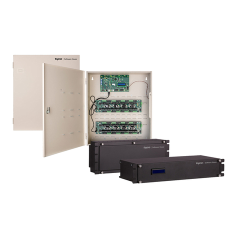
Tyco Galaxy SC Controller User manual

Part 1
Galaxy SC Controller
J85501F-1
Product Manual
Select Code 167-790-060
Comcode 107330946
Issue 13
February 2001


Product Manual
Part 1
Select Code 167-790-060
Comcode 107330946
Issue 13
February 2001
Galaxy SC Controller
J85501F-1
Notice:
Every effort was made to ensure that the information in this
document was complete and accurate at the time of printing.
However, information is subject to change.
© 2001 Tyco Electronics Corporation, Harrisburg, PA.
All Rights Reserved
Printed in U.S.A.


Tyco Electronics Galaxy SC Controller J85501F-1
Issue 13 February 2001 Table of Contents - 1
Table of Contents
1 Introduction
The Product 1 - 1
The Product Manual 1 - 2
Customer Service Contacts 1 - 3
Customer Service 1 - 3
Customer Training 1 - 3
Technical Support 1 - 3
Product Repair and Return 1 - 3
Warranty Service 1 - 3
On-Line Power Systems Product Manuals 1 - 3
EasyView Software 1 - 3
2 Product Description
Overview 2 - 1
Basic Controller 2 - 2
Intelligent Controller 2 - 2
Backplane 2 - 3
Circuit Packs Used in the Galaxy SC Controller 2 - 4
BJA1 or BJA2 (Basic Controller Power Board) 2 - 4
BJB1 (Basic Controller Digital Board) 2 - 4
BJC1, BJC2 or BJC3 (Rectifier Interface Board) 2 - 4
BJE3 (Relay/Alarm/Display Driver Board) 2 - 4
BJF1 or BJF2 (Termination Fuse Board) 2 - 5
BJT1 (Termination Board) 2 - 5
BJG1 (Display Board) 2 - 5
BJJ1 or BJJ2 (Intelligent Controller Power Boards) 2 - 5
BJH (Intelligent Controller Board) 2 - 5
BJL2 (Modem Board) 2 - 5
BJM1 (Peripheral Monitoring Board) 2 - 5
BJK1 (Data Switch) 2 - 5
BJD1 (Galaxy Gateway Network Communication Card) 2 - 6
Interface Modules 2 - 6
User Interface and Display 2 - 6
LEDs 2 - 7
Test Jacks 2 - 7
Pushbutton Keys 2 - 8

Tyco Electronics Galaxy SC Controller J85501F-1
2 - Table of Contents Issue 13 February 2001
Display Software Version 2 - 8
Display Language 2 - 8
Display Conventions 2 - 9
Default Display 2 - 9
Menu Organization 2 - 10
Menu Operations 2 - 12
3 Installation
Overview 3 - 1
Precautions 3 - 1
Tools 3 - 1
New Plant Installation 3 - 2
Grounding 3 - 2
Rectifier Interface Modules 3 - 2
Mixing Types of Rectifiers 3 - 4
Circuit Packs 3 - 5
DIP Switch Settings 3 - 7
Memory Battery 3 - 15
Controller Fusing 3 - 15
Power, Regulation, and Shunt Inputs 3 - 16
Rectifier/Converter Control Cables 3 - 17
Fuse/CB Alarm Wiring 3 - 22
Optional Feature Wiring 3 - 22
Battery Connections 3 - 23
Power Up the Controller 3 - 24
Galaxy SC Configuration 3 - 24
Rectifier VI Circuit Adjustment 3 - 24
Galaxy SC External Alarms 3 - 25
MCS Controller Retrofit 3 - 27
Safety Precautions 3 - 27
Power Down MCS 3 - 27
Disconnect Rectifiers From MCS control 3 - 28
Remove TB1 Alarm Wiring 3 - 29
Remove Power and Miscellaneous Cabling From MCS 3 - 31
Remove MCS Controller 3 - 31
Mount the Galaxy Controller 3 - 32
Rectifier Interface Modules 3 - 32
Galaxy Circuit Packs 3 - 33
DIP Switch Settings 3 - 33
Memory Battery 3 - 33
Controller Fusing 3 - 34
Power, Regulation, and Shunt Inputs 3 - 34
Reconnect Alarm Wiring 3 - 34
Optional Feature Wiring 3 - 34
Power Up Galaxy Controller 3 - 34

Tyco Electronics Galaxy SC Controller J85501F-1
Issue 13 February 2001 Table of Contents - 3
Place Plant Rectifiers Under Galaxy Control 3 - 35
Galaxy SC Configuration 3 - 35
Rectifier VI Circuit Adjustment 3 - 35
Galaxy Option Features 3 - 36
Intelligent Controller (J85501F1 L- AB or AC) 3 - 36
Modem (J85501F1 L-AE) 3 - 38
Data Switch (J85501F1 L-AH) 3 - 38
Remote Peripheral Monitoring (J85501F1 L-AG, J85501G1) 3 - 46
Battery Reserve Time Prediction (J85501F1 L-K1) 3 - 49
Wiring Options 3 - 49
Rectifier Sequencing 3 - 49
Supplemental Alarm Input 3 - 51
External Boost 3 - 52
Battery Thermal Protection 3 - 52
Circuit Pack Addition, Removal, and Replacement 3 - 53
4 Configuration
Introduction 4 - 1
Methods of Configuring Galaxy 4 - 6
Front Panel 4 - 6
EasyView Software 4 - 6
Remote Terminal 4 - 6
Basic Controller Configuration From the Front Panel 4 - 7
Plant Menu 4 - 7
Alarm Thresholds Menu 4 - 12
Alarm Menu 4 - 14
Rectifier Menu 4 - 15
Rectifier Management Menu 4 - 15
Slope Thermal Compensation Menu 4 - 17
Low Voltage Disconnect Menu 4 - 18
Converter Management Menu 4 - 20
Battery Discharge Test Menu 4 - 21
Intelligent Controller Configuration Via Front Panel
or EasyView Software 4 - 22
Plant Menu 4 - 22
System Date Menu 4 - 26
System Time Menu 4 - 26
Alarm Thresholds Menu 4 - 27
Alarm Menu 4 - 29
Rectifier Manager Menu 4 - 30
Rectifier Definition Menu 4 - 30
Rectifiers Control Parameters Menu 4 - 31
Rectifier Operation Menu 4 - 33
Boost Menu 4 - 34
Battery Manager Menu 4 - 35

Tyco Electronics Galaxy SC Controller J85501F-1
4 - Table of Contents Issue 13February 2001
Slope Thermal Compensation Menu 4 - 35
Battery Control Menu 4 - 36
Battery Discharge Test Menu 4 - 37
Communication Ports (PORT) Menu 4 - 39
Low Voltage Disconnect Menu 4 - 40
Converter Management Menu 4 - 42
EasyView Software Communication Mode 4 - 43
EasyView Configuration 4 - 44
Alarm Cut-Off Feature 4 - 47
Alarms Overview 4 - 47
Connected Equipment Alarms 4 - 48
Standard Alarms 4 - 48
Threshold Alarms 4 - 48
User Defined Alarms 4 - 49
Alarm Test 4 - 50
Battery Bay 4 - 50
Contactor 1 Contactor 2 Contactor 3 4 - 50
Reserve 4 - 51
Battery Section 4 - 52
Slope Thermal Compensation 4 - 53
Boost 4 - 54
Call Back Security 4 - 55
Call-Out Phone Numbers 4 - 55
Call-Out Nag Interval 4 - 55
Call-Out Periodic Call Out 4 - 56
Passwords 4 - 56
Data Switch 4 - 56
DC Plant Hardware and Software 4 - 56
DC Plant Software 4 - 57
AC Distribution Links 4 - 58
DC Distribution Links 4 - 59
Maintenance Reminders 4 - 59
Notepads 4 - 59
Controller Option Inventory 4 - 59
Controller Distribution Inventory 4 - 59
Peripheral Monitor Inventory 4 - 59
Plant Inventory 4 - 59
Rectifier Inventory 4 - 59
Reserve Inventory 4 - 60
Communication Ports 4 - 60
Rectifier Bays 4 - 60
Rectifiers 4 - 60
Rectifier Manager 4 - 61
Statistics 4 - 62
Trend Studies 4 - 62
System Hardware and Software 4 - 62

Tyco Electronics Galaxy SC Controller J85501F-1
Issue 13 February 2001 Table of Contents - 5
System Software 4 - 63
System Time 4 - 63
Timer Events 4 - 64
Configuration From a Remote Terminal 4 - 64
T1.317 Command Language 4 - 64
Connecting a Terminal to Galaxy SC 4 - 64
5 Acceptance Testing
Introduction 5 - 1
Tools and Test Equipment 5 - 1
Precautions 5 - 1
Lamp Test 5 - 1
Alarm Test 5 - 2
Local Alarm Test 5 - 2
Remote Alarm Test 5 - 3
High Float Voltage Alarm (Serial Rectifiers) 5 - 3
New Installations (Serial Rectifiers) 5 - 3
Installations Serving An Active Plant Load (Serial Rectifiers) 5 - 4
High Voltage Shutdown - New Installations Only
(Serial Rectifiers) 5 - 4
High Voltage Alarm/High Voltage Shutdown Alarm
(Parallel Rectifiers) 5 - 7
New Installations (Parallel Rectifiers) 5 - 7
Installations Serving an Active Plant Load
(Parallel Rectifiers) 5 - 8
Batteryless Plant HVSD Test (Serial Rectifiers) 5 - 9
Battery on Discharge Alarm 5 - 10
Rectifier Fail Alarm 5 - 10
Terminate Rectifier (TR) Test 5 - 12
Fuse Alarm Tests 5 - 12
Major Fuse Alarm 5 - 12
Minor Fuse Alarm 5 - 13
Modem/Data Switch 5 - 13
Remote Peripheral Monitoring 5 - 13
Rectifier Sequencing 5 - 13
Energy Management 5 - 14
Meter Calibration From the Front Panel 5 - 14
Voltage Calibration 5 - 14
Current Calibration 5 - 15
6 Operation
Introduction 6 - 1
Basic Controller’s Front Panel Operation 6 - 1
Alarm Cut Off 6 - 1

Tyco Electronics Galaxy SC Controller J85501F-1
6 - Table of Contents Issue 13February 2001
Change Plant Mode 6 - 2
Change Plant Voltage (Serial Bus Rectifiers Only) 6 - 2
Clear Latched Events 6 - 2
Display Alarm Data 6 - 2
Display Warning Data 6 - 2
Performing Rectifier Restart 6 - 3
Remove Rectifier Configuration (Serial Bus Rectifiers Only) 6 - 3
Intelligent Controller’s Front Panel Operation 6 - 3
Performing ACO 6 - 3
Change Plant Mode 6 - 3
Change Plant Voltage (Serial Bus Rectifiers Only) 6 - 4
Clear Latched Events 6 - 4
Disable/Enable Efficiency 6 - 4
Display Alarm Data 6 - 4
Display Warning Data 6 - 4
Performing Rectifier Restart 6 - 4
Remove Rectifier Configuration (Serial Bus Rectifiers Only) 6 - 5
Viewing and Clearing History, Statistics 6 - 5
Viewing History 6 - 5
Clearing History 6 - 6
Viewing Statistics 6 - 6
Viewing Maintenance Reminders 6 - 7
Viewing the Notepad 6 - 7
Clearing Statistics 6 - 8
Viewing Measurement Data 6 - 8
Diagnostics 6 - 10
EasyView Common Access and Control Functions 6 - 10
ACO Operation (Alarm Cut Off) 6 - 10
Alarm Test Operation 6 - 10
Backup/Restore 6 - 10
Boost/Float Mode Control 6 - 11
Changing Plant Voltage (Serial Bus Rectifiers Only) 6 - 11
Clear Latched Events 6 - 11
Diagnostics 6 - 11
Disable/Enable Efficiency 6 - 11
Display Alarms and Warnings 6 - 11
Display Alarm Test 6 - 12
Display Battery Sections 6 - 12
Display DC Plant 6 - 12
Display Distribution AC 6 - 12
Display Distribution DC 6 - 12
Display Record Only Alarms 6 - 12
Display Rectifier 6 - 12
Display Rectifier Bays 6 - 12
History 6 - 12
Measurements 6 - 13

Tyco Electronics Galaxy SC Controller J85501F-1
Issue 13 February 2001 Table of Contents - 7
Rectifier Control 6 - 13
Rectifier Removal (Serial Bus Rectifiers Only) 6 - 13
Rectifier Restart 6 - 13
Statistics 6 - 13
T1.317 Interface Common Access and Control Functions 6 - 14
AC Distribution Management 6 - 14
Alarm Test Management 6 - 14
Alarm Configuration 6 - 15
Configuring Alarms to Call-Out 6 - 16
Viewing Active Alarms 6 - 17
Battery Management 6 - 17
Building Battery Configurations 6 - 17
Linking Remote Monitoring Channels 6 - 17
Battery Parameter Configuration 6 - 18
Contactor Management 6 - 19
Clearing Active Alarms 6 - 20
Configuration Backup 6 - 20
Configuration Restore 6 - 20
Boost Management 6 - 21
Call-Out Configuration 6 - 21
Call-Out Phone Number Management 6 - 22
Configuring Alarms to Call-Out 6 - 22
Pass-Through Mode 6 - 22
Alarm Reporting Mode 6 - 23
DC Distribution Management 6 - 24
Derived Channel Management 6 - 24
Energy Management 6 - 25
Alarm History Management 6 - 25
Rectifier State History Management 6 - 26
Battery Discharge History Management 6 - 26
Boost State History Management 6 - 27
Login State History Management 6 - 27
Inventory Management 6 - 27
Maintenance Reminder Management 6 - 28
Notepad Management 6 - 29
Periodic Status Call-Out Configuration 6 - 30
Rectifier Control Usage 6 - 30
Rectifier Management 6 - 31
Remote Peripheral Monitor Management 6 - 32
Reserve Time Prediction 6 - 34
Security Level and Password Management 6 - 34
Access Port Security Hardware/Software Switch
Management 6 - 35
Call-Back Security Management 6 - 35
Security Event Management 6 - 36
Serial Access Port Management 6 - 36

Tyco Electronics Galaxy SC Controller J85501F-1
8 - Table of Contents Issue 13February 2001
Upgrading the Intelligent Controller Software 6 - 37
Statistics Usage 6 - 38
Timer Events Management 6 - 38
User-Defined Event Management 6 - 39
7 Feature Descriptions
AC Distribution 7 - 2
Alarm Cut-Off (ACO) 7 - 2
Parameters 7 - 3
Alarm Test 7 - 3
Parameters 7 - 4
Backup and Restore 7 - 6
Battery Discharge Test 7 - 6
Battery Sections 7 - 8
Boost 7 - 10
Boost Modes 7 - 13
Boost Qualifying Reasons 7 - 13
Boost Parameters 7 - 14
T1.317 Boost usage 7 - 14
Call-Out 7 - 15
Call-out Phone Number Configuration Parameters 7 - 15
Alarm Call-out Configuration Parameters 7 - 16
Call-Out on Alarm Algorithm 7 - 16
Alarms Generated by Call-Out 7 - 17
Queue Overflow 7 - 17
Number Did Not Respond 7 - 17
Number Not Configured 7 - 17
Controller Failure 7 - 18
Data Switch 7 - 18
Data Switch Configuration Parameters 7 - 19
Defaults 7 - 20
Data Switch Alarm Configuration Parameters 7 - 21
Pass-Through Mode 7 - 21
Alarm Reporting Mode 7 - 22
DC Distribution 7 - 22
Derived Channels 7 - 23
Energy Management 7 - 23
Parameters 7 - 25
History Logs 7 - 25
Alarm History 7 - 25
Rectifier State History 7 - 26
Battery Discharge History 7 - 26
Boost State History 7 - 26
Login State History 7 - 27
Inventory 7 - 27

Tyco Electronics Galaxy SC Controller J85501F-1
Issue 13 February 2001 Table of Contents - 9
Low Voltage Disconnect (LVD) 7 - 28
Low Voltage Load Disconnect (LVLD) 7 - 28
Low Voltage Battery Disconnect (LVBD) 7 - 29
Maintenance Reminder 7 - 31
Notepad 7 - 31
Periodic Status Call-Out 7 - 31
Rectifier Bays 7 - 32
Rectifier Off Conditions 7 - 33
Rectifier Standby Conditions 7 - 33
External Rectifier Sequencer 7 - 34
Internal Rectifier Sequencer 7 - 34
Operator Rectifier Control 7 - 35
Rectifier Restart 7 - 36
Remote Rectifier Turn On 7 - 36
Remote Rectifier Turn Off 7 - 36
Overriding Rectifier Standby Conditions 7 - 36
Low Plant Voltage Conditions 7 - 36
Invalid Engine Signals 7 - 37
Rectifier Control Parameters 7 - 37
Rectifier Manager 7 - 39
Rectifier Monitoring and Control 7 - 40
Remote Peripheral Monitoring Modules and Channels 7 - 40
Voltage Modules 7 - 43
Shunt Modules and Channels 7 - 44
Temperature Modules and Channels 7 - 44
Binary Modules and Channels 7 - 44
Control Relay Modules and Channels 7 - 44
Security 7 - 45
Security Levels/Passwords 7 - 45
Access Port Security Hardware/Software Switches 7 - 46
Call-Back Security 7 - 46
Security Events 7 - 47
Serial Access Ports 7 - 47
Local Port 7 - 47
Auxiliary Port 7 - 48
Modem Port 7 - 49
Enhanced Remote Security Via Modem Port and
Auxiliary Port 7 - 50
Slope Thermal Compensation 7 - 51
Software Upgrade 7 - 52
Statistics 7 - 53
Basic Statistics 7 - 54
Trend Statistics 7 - 54
Busy Hour Statistics 7 - 54
Battery Discharge Statistics 7 - 54
Effect of Power Failure 7 - 55

Tyco Electronics Galaxy SC Controller J85501F-1
10 - Table of Contents Issue 13February 2001
Effect of Changing Date and Time 7 - 56
Effect of Changing Scale Factor, Range or Channel Type 7 - 56
Terminal Menu Interface 7 - 56
Timer Events 7 - 56
User Defined Events 7 - 57
Legal Operators for UDEs 7 - 57
Examples 7 - 60
Universal Reserve Time Prediction 7 - 62
Installation 7 - 64
Parameters 7 - 64
8 Troubleshooting
Basic Controller Circuit Packs 8 - 1
BJB Microprocessor Board 8 - 1
Other Basic Boards 8 - 2
BJA Power Board 8 - 2
Front Panel Display 8 - 2
Intelligent Controller Circuit Packs 8 - 3
BJH Microprocessor Board 8 - 3
BJJ Power Board 8 - 3
Intelligent Option Boards 8 - 4
Replacing a Memory Backup Battery 8 - 4
Backup System Configuration 8 - 4
Replace Battery 8 - 5
Restore System Configuration 8 - 6
Alarms 8 - 7
9 Safety
Safety Statements 9 - 1
Warning Statements and Safety Symbols 9 - 4
Precautions 9 - 6
10 Product Warranty
Appendix A T1.317 Interface
Overview A - 1
Login A - 1
Login Header A - 2
Objects and Attributes A - 2
Commands A - 3
Syntax A - 4

Tyco Electronics Galaxy SC Controller J85501F-1
Issue 13 February 2001 Table of Contents - 11
Operation Commands A - 5
Reporting Commands A - 10
System Defined Aliases A - 14
Error Reporting A - 15
Appendix B T1.317 Objects and Attributes
Appendix C T1.317 Error Messages
Error Messages and Causes C - 1
Syntax Related C - 1
Security Related C - 2
Command Execution Related C - 2
Diagnostic Messages C - 6
Appendix D TL1 (Transaction Language 1) and X.25
Interface
Introduction D - 1
Equipment Setup and Installation D - 1
Tools and Parts D - 2
Galaxy Unit Setup D - 3
PAD Unit Setup D - 3
PAD Setup D - 7
PVC Port Setup D - 10
SVC Port Setup D - 10
Debugging TL1 D - 11
Debugging OS to PAD Connection D - 11
Test the RS-232/485 Converter to Galaxy D - 13
Test the OS to PAD D - 14
General Operational Considerations D - 14
Galaxy TL1 Configuration D - 15
Auxiliary Port D - 15
Backup or Restore D - 15
Command Format D - 16
Command D - 16
TID (Target Identification) D - 16
AID (Access Identification) D - 16
CTAG (Correlation Tag) D - 17
GB (General Block) and PB (Parameter Block) D - 17
Condition Type D - 17
Service-Affecting D - 17
Setup Procedure for Galaxy to Communicate Messages
With Operating Systems (OSs) D - 17

Tyco Electronics Galaxy SC Controller J85501F-1
12 - Table of Contents Issue 13February 2001
TL1 Commands Supported by Galaxy D - 18
Commands from OSs D - 19
Autonomous Commands From Galaxy (NE) to OS D - 25
Bellcore Reference Documents D - 26
Appendix E Terminal Menu Interface
Login E - 1
Menus E - 2
Appendix F Spare Parts
Appendix G Glossary

Tyco Electronics Galaxy SC Controller J85501F-1
Issue 13 February 2001 List of Figures - 1
List of Figures
Figure 1-1: Galaxy SC Controller 1 - 1
Figure 2-1: Galaxy SC Controller With Door Open
(Basic Circuit Packs At Right of Cabinet,
Intelligent Circuit Packs At Left) 2 - 2
Figure 2-2: Galaxy SC Controller Rectifier Interface Modules 2 - 6
Figure 2-3: Galaxy SC Controller Front Panel 2 - 7
Figure 2-4: Hierarchical Overview of Basic Controller Menu
(Version 7.3.0) 2 - 10
Figure 2-5: Hierarchical Overview of Intelligent Controller
(Version 7.3.0) 2 - 11
Figure 3-1: Details of Galaxy SC’s Circuit Board Positions 3 - 4
Figure 3-2: BJF Circuit Pack 3 - 16
Figure 3-3: Shunt Diagram 3 - 17
Figure 3-4: Control Cable Connectors 3 - 18
Figure 3-5: BJT1 Terminal Block 3 - 25
Figure 3-6: MCS TB1 Alarm Connections 3 - 29
Figure 3-7: RS485 and RS232 Auxiliary Port Connections
for PAD/DSU (Top) and PC or Non-PAD/DSU (Bottom) 3 - 37
Figure 3-8: Data Switch Interface Card 3 - 39
Figure 3-9: Connections from Galaxy Data Switch
to ECS Controller, OMNIpulse, or Another Galaxy 3 - 42
Figure 3-10: Connections from Galaxy Data Switch to RAS 3 - 43
Figure 3-11: Connections from Galaxy Data Switch
to MCS Controller Remote Interface Pack 3 - 44
Figure 3-12: Connections from Galaxy Data Switch
to XCS Controller 3 - 44

Tyco Electronics Galaxy SC Controller J85501F-1
2 - List of Figures Issue 13 February 2001
Figure 3-13: Connections from Galaxy Local Port
to PC/Printer (top) and PAD/DSU (bottom) 3 - 45
Figure 3-14: Connecting Remote Peripheral Interface
Bus Wiring to Galaxy SC Controller 3 - 47
Figure 3-15: Wiring for Rectifier Sequencing
(TFLT=Tell to Float; TBST=Tell to Boost) 3 - 50
Figure 3-16: Wiring for External Boost Option 3 - 52
Figure 3-17: Connections for Battery Thermal Protection 3 - 53
Figure 4-1: EasyView Main Screen 4 - 44
Figure 4-2: EasyView Configure Menu 4 - 45
Figure D-1: TL1 Block Diagram D - 2
Figure D-2: PAD CPU Board D - 3
Figure D-3: PAD Daughter Board D - 4
Figure D-4: PAD and DSU Mounting Shelf D - 5
Figure D-5: PAD Power Cable Setup D - 7

Tyco Electronics Galaxy SC Controller J85501F-1
Issue 13 February 2001 List of Tables - 1
List of Tables
Table 3-A: Standard Galaxy SC Controller Circuit Packs 3 - 6
Table 3-B: Galaxy SC High Voltage Shutdown Setting -48V 3 - 8
Table 3-C: BJA High Voltage Shutdown Setting +/-24V 3 - 11
Table 3-D: Switch Positions for Galaxy Controller Basic
and Intelligent Boards 3 - 14
Table 3-E: Galaxy Controller Rectifier and Cabling Information 3 - 19
Table 3-F: Galaxy SC Controller Commercial Rectifier Cable
(H285-226 G62) Connection Information 3 - 21
Table 3-G: J85501F-1 List Options 3 - 23
Table 3-H: Alarm Signal Outputs 3 - 26
Table 3-I: MCS/Galaxy Alarm Connections 3 - 30
Table 3-J: Data Switch Cable Interface 3 - 40
Table 4-A: Voltage Threshold Ranges and Default Values 4 - 2
Table 4-B: Plant Alarm Severity, LED, and Relay Defaults 4 - 3
Table 4-C: Rectifier Alarm Defaults 4 - 5
Table 7-A: Remote Security Via Modem and Auxiliary Ports 7 - 50
Table 8-A: Galaxy Alarms 8 - 7
Table B-1: System Objects and Attributes B - 2
Table B-2: DC Distribution Objects and Attributes B - 3
Table B-3: AC Distribution Objects and Attributes B - 4
Table B-4: Alarm Test Objects and Attributes B - 5
Table B-5: DC Plant Objects and Attributes B - 6
Table B-6: Boost Objects and Attributes B - 8

Tyco Electronics Galaxy SC Controller J85501F-1
2 - List of Tables Issue 13 February 2001
Table B-7: Rectifiers Objects and Attributes B - 9
Table B-8: Converter Management Objects and Attributes B - 10
Table B-9: Battery Management Objects and Attributes B - 11
Table B-10: Alarm And Events Objects and Attribute B - 13
Table B-11: Data Switch Objects and Attributes B - 16
Table B-12: Remote Peripheral Monitor Objects and Attributes B - 17
Table B-13: Reporting Objects and Attributes B - 18
Table B-14: Remote Communication Objects and Attributes B - 19
Table B-15: Configurable Statistics Objects and Attributes B - 20
Table B-16: Inventory Objects and Attributes B - 21
Table B-17: TL1 Management Objects and Attributes B - 23
Table B-18: Miscellaneous Objects and Attributes B - 24
Table C-1: Galaxy Diagnostic Messages C - 6
Table D-1: Pad Jumper Settings D - 4
Table D-2: RS-232/485 Converter DIP Switch Settings D - 6
Table D-3: Wiring Connections From Galaxy Aux Port
TB2 to RS-232/485 Converter D - 6
Table D-4: PAD Messages D - 8
Table F-1: Spare Parts F - 1
This manual suits for next models
1
Table of contents
Other Tyco Controllers manuals

Tyco
Tyco iSTAR eX Operator's manual

Tyco
Tyco DigiTrace 920 Series Installation guide

Tyco
Tyco Software House iSTAR eX User manual

Tyco
Tyco DSC PowerSeries HS2016 User manual

Tyco
Tyco DN40 User manual

Tyco
Tyco G2 User manual

Tyco
Tyco iSTAR Ultra G2 SE User manual
Tyco
Tyco TL880LE User manual

Tyco
Tyco DSC PowerSeries neo User manual

Tyco
Tyco VIZOR EDPA User manual