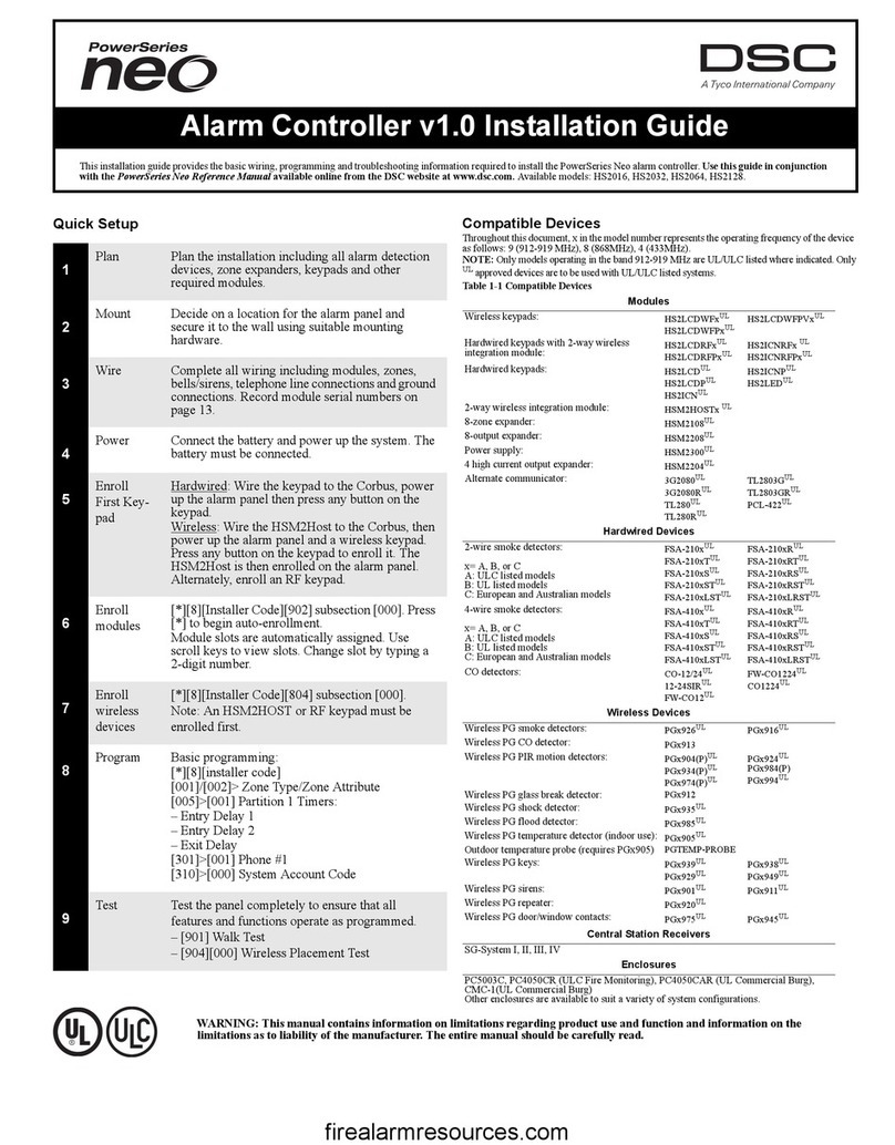
Tyco DSC PowerSeries HS2016 User manual

PowerSeries Neo Alarm Controller
V1.0 Reference Manual
Models:
HS2016/HS2032/HS2064/HS2128
WARNING: This manual contains information on limitations regarding product use and function and
information on the limitations as to liability of the manufacturer. The entire manual should be carefully
read.
firealarmresources.com

Contents
i
1: Introduction . . . . . . . . . . . . . . . . . . . . 1
About the System.....................................1
Features............................................................. 1
Available Models .............................................. 1
Compatible Devices.......................................... 2
2: Installation . . . . . . . . . . . . . . . . . . . . . 3
Overview of Installation Process............3
Alarm Controller Installation ................3
Mounting the Enclosure.................................... 3
Wiring.......................................................3
Terminal Descriptions....................................... 3
Wire Routing for Power & Non-Power Limited4
Corbus Wiring................................................... 4
Installing Modules ...................................5
Zone Expander.................................................. 5
Output Expander............................................... 5
Wireless Transceiver Module ........................... 5
Power Supply Wiring........................................ 5
Keypad Wiring.................................................. 6
Assigning Keypad Zones.................................. 6
Audio Verification Module ............................... 6
Alternate Communicator Wiring ...................... 6
Zone Wiring...................................................... 6
PGM Wiring...................................................... 7
Bell Wiring........................................................ 7
Telephone Line Wiring ..................................... 8
Smoke Detector Wiring .................................... 8
Fire Zone Wiring: 2-wire Smoke Detectors...... 8
CO Detector ...................................................... 8
Ground Wiring.................................................. 9
Connecting Power............................................. 9
3: Configuration . . . . . . . . . . . . . . . . . . 10
Basic Configuration Steps.....................10
Using the Keypad...................................10
Special Keys ................................................... 10
LED Indicators................................................ 10
Enrollment..............................................10
Enrolling Modules .......................................... 10
Module Supervision.........................................11
Enroll Wireless Devices...................................11
Working with Partitions .......................11
Setting Up a Partition.......................................11
Bell/Siren Operation ........................................11
Trouble Indicators .................................12
Keypad Partition Setup.........................12
Global Zones................................................... 12
Fire and CO Zone Types................................. 12
Bell/PGM Support .......................................... 12
Communications ............................................. 12
Factory Defaults .............................................. 12
Alternate Communicator Setup........... 12
Real Time Clock.............................................. 13
Communication Paths ..................................... 13
Communications Options................................ 13
Communication Attempt Limit ....................... 13
Supervision Restore ........................................ 13
Remote Firmware Upgrade ............................. 13
Local Firmware Upgrade ..................... 13
Testing the System................................. 13
Walk Test......................................................... 13
Viewing the Event Buffer................................ 13
4: System Operation. . . . . . . . . . . . . . . 14
Arming and Disarming......................... 14
Partition vs. Global Keypad................. 14
Labels ..................................................... 14
System Label................................................... 14
Zone Labels..................................................... 14
Partition Labels ............................................... 14
Module Labels................................................. 14
Event Labels.................................................... 15
Partition Command Output Labels.................. 15
Annunciation ......................................... 15
Door Chime..................................................... 15
Temperature Display ....................................... 15
Low Temperature Warning.............................. 15
Keypad Function Keys ......................... 15
Function Key Definitions................................15
Language Selection ............................... 16
[*] Commands ....................................... 16
[*][1] Bypass or Stay/Away/Night Zones ....... 17
[*][2] Trouble Display .................................... 17
[*][3] Alarm Memory Display........................ 18
[*][4] Door Chime Enable/Disable ................. 19
[*][5] Program Access Codes .........................19
[*][6] User Functions ...................................... 21
[*][7] Command Outputs 1-4.......................... 22
[*][8] Installer Programming .......................... 22
[*][9] No-Entry Arming..................................22
[*][0] Quick Arm/Exit..................................... 22
SMS Command and Control................ 22
SMS Command and Control Functions .......... 22
Visual Verification................................. 23
5: Programming . . . . . . . . . . . . . . . . . . 24
How to Program.................................... 24
Programming Methods......................... 24
Template Programming ................................... 24
firealarmresources.com

Contents
ii
DLS Programming.......................................... 24
Installer Programming .................................... 25
Viewing Programming.................................... 25
Programming Hex and Decimal Data............. 25
Programming Descriptions...................26
Adding Labels................................................. 26
Zone Setup ...................................................... 27
System Times.................................................. 30
Access Codes .................................................. 30
PGM Configuration ........................................ 31
PGM Types ..................................................... 31
System Options............................................... 37
Partition Setup ................................................ 42
Reporting ........................................................ 43
System Communications ................................ 46
DLS Programming.......................................... 50
Schedule Programming................................... 52
Wireless Programming.................................... 52
Systems Information ....................................... 53
Module Programming..................................... 53
Testing............................................................. 54
Defaults........................................................... 54
6: Programming Worksheets . . . . . . . 55
7: Troubleshooting. . . . . . . . . . . . . . . . 93
Testing.....................................................93
Troubleshooting .....................................93
Appendix A : Event Codes . . . . . . . . . 98
Appendix B : Word Library . . . . . . . 104
Appendix C : Template Programming
Tables . . . . . . . . . . . . . . . . . . . . . . . . . 105
Appendix D : Regulatory Approvals 110
UL/ULC Installations ....................................111
SIA False Alarm Reduction Installations: Quick
Reference ...........................................................................113
Appendix E : ASCII Characters. . . . 114
Appendix F : Wiring Diagrams . . . . 115
Appendix G : Specifications . . . . . . . 119
Appendix H : Index . . . . . . . . . . . . . . 122
firealarmresources.com

xxv
Before Installing The Equipment
Ensure your package includes the following items:
• Installation and User manuals, including the SAFETY INSTRUCTIONS.
READ and SAVE these instructions!
Follow all WARNINGS AND INSTRUCTIONS specified within this document and/or on the equipment.
• HS2016/2032/2064/2128 alarm controller
• Power Supply, direct plug-in
•Mountinghardware
Safety Instructions for Service Personnel
Warning: When using equipment connected to the telephone network, always follow the basic safety instructions provided with this product.
Save these instructions for future reference. Inform the end-user of the safety precautions that must be observed when operating this equipment.
Selecting A Suitable Location For The Alarm Controller
Use the following list as a guide to find a suitable location to install this equipment:
• Locate near a telephone socket and power outlet.
• Select a location free from vibration and shock.
• Place alarm controller on a flat, stable surface and follow the installation instructions.
Do NOT locate this product where people may walk on the secondary circuit cable(s).
Do NOT connect alarm controller to electrical the same circuit as large appliances.
Do NOT select a location that exposes your alarm controller to direct sunlight, excessive heat, moisture, vapors, chemicals or dust.
Do not install this equipment near water. (e.g., bath tub, kitchen/laundry sink, wet basement, near a swimming pool).
Do NOT install this equipment and accessories in areas where risk of explosion exists.
Do NOT connect this equipment to electrical outlets controlled by wall switches or automatic timers.
AVOID interference sources.
AVOID installing equipment near heaters, air conditioners, ventilators, and refrigerators.
AVOID locating equipment close to or on top of large metal objects (e.g., wall studs).
• See page 120 for information on locating smoke and CO detectors.
SAFETY Precautions Required During Installation
•NEVER install this equipment and/or telephone wiring during a lightning storm.
•NEVER touch uninsulated telephone wires or terminals unless the telephone line has been disconnected at the network interface.
• Position cables so that accidents can not occur. Connected cables must NOT be subject to excessive mechanical strain.
• Use only the power supply provided with this equipment. Use of unauthorized power supplies may cause damage.
• For direct plug-in versions, use the transformer supplied with the device.
WARNING:
THIS EQUIPMENT HAS NO MAINS ON/OFF SWITCH. THE PLUG OF THE DIRECT PLUG-IN POWER SUPPLY IS INTENDED TO
SERVE AS THE DISCONNECTING DEVICE IF THE EQUIPMENT MUST BE QUICKLY DISCONNECTED. IT IS IMPERATIVE THAT
ACCESS TO THE MAINS PLUG AND ASSOCIATED MAINS SOCKET/OUTLET IS NEVER OBSTRUCTED.
IMPORTANT NOTE!
This alarm system must be installed and used within an environment
that provides the pollution degree max 2 and over-voltages category
II NON-HAZARDOUS LOCATIONS, indoor only. The equipment is
DIRECT PLUG-IN (external transformer) and is designed to be
installed, serviced and/or repaired by service persons only; [service
person is defined as a person having the appropriate technical
training and experience necessary to be aware of hazards to which
that person may be exposed in performing a task and of measures to
minimize the risks to that person or other persons]. There are no
parts replaceable by the end-user within this equipment. The wiring
(cables) used for installation of the alarm system and accessories,
shall be insulated with PVC, TFE, PTFE, FEP, Neoprene or
Polyamide.
(a) The equipment enclosure must be secured to the building
structure before operation.
(b) Internal wiring must be routed in a manner that prevents:
- Excessive strain or loosening of wire on terminal connections;
- Damage of conductor insulation
(c) Disposal of used batteries must be made in accordance with
local waste recovery and recycling regulations.
(d) Before servicing, DISCONNECT the power and telephone
connection.
(e) DO NOT route any wiring over circuit boards.
(f) The installer is responsible to ensure that a readily accessible
disconnect device is incorporated in the building for permanently
connected installations.
The power supply must be Class II, FAIL SAFE with double or reinforced insulation between the PRIMARY and SECONDARY CIRCUIT/
ENCLOSURE and be an approved type acceptable to the local authorities. All national wiring rules must be observed.
firealarmresources.com

1
Section 1: Introduction
1.1 About the System
The PowerSeries Neo alarm panel is a feature-rich, scalable alarm
system designed for residential and light commercial use. The alarm
panel supports both hardwired and wireless devices. This section lists
the features of the alarm panel, available models, and compatible
devices.
1.1.1 Features
The following features are available on the PowerSeries Neo alarm
controller.
Zones
• 16, 32, 64, or 128 wireless zones supported and 8 hardwired
zones available on the controller
• 40 zone types and 14 programmable zone attributes
• Up to 16 separate wireless keypads supported
• Up to 32 separate wireless keys or panic pendants supported
• Up to 95 separate proximity tags supported
Access Codes
• Up to 98 access codes: one system master code, one installer
code, and one maintenance code
• Programmable attributes for each user code (see page 20)
Programmable Outputs (PGMs)
• Up to 4 programmable outputs (PGM) on the alarm controller
with 41 available options
• 148, 80, 38, 22 maximum programmable outputs
System Supervision Features
• The PowerSeries Neo continuously monitors a number of possi-
ble trouble conditions and provides audible and visual indica-
tion at the keypad. Trouble conditions include:
• AC power failure
• Zone trouble
• Fire trouble
• Telephone line trouble
• Communicator trouble
• Low battery condition
• RF jam
• AUX power supply fault
• Failure to communicate
• Module fault (supervisory or tamper)
Additional Features
• 2-way wireless device support
• Visual verification (images + audio)*
• Proximity tag support
• PGM scheduling
• Quick arming
• User, partition, module, zone and system labels
• Programmable system loop response
• Keypad and panel software versions viewable through keypad
• Doorbell zone type
• Low battery PGM type
1.1.2 Available Models
The following alarm controller models are available:
• HS2016
• HS2032
• HS2064
• HS2128
Model Differences
The table below lists the features of each alarm system model.
Table 1-1 Model Differences
*For UL installations, 2 repeaters must be installed for proper signal
routing.
Features HS2128 HS2064 HS2032 HS2016
Hardwired zones 128 64 32 16
Onboard zone inputs 8 8 8 6
Wireless zones 128 64 32 16
Partitions 8842
Users 95957248
Onboard outputs 4 4 2 2
Max outputs 148 80 38 22
Keypads 16 8 8 8
Wireless keys 32 32 32 16
Wireless sirens 16 8 8 4
Wireless repeaters *8 8 8 4
Proximity tags 94 94 71 47
Alt Comm. phone #’s 4 4 4 4
User-programmable
phone #’s 8888
Lifesafety event buffer 1000 500 500 500
8-zone expander
HSM2108 15 7 3 1
Power supply
HSM2300 4333
Power supply/high-
current output
expander HSM2204
4311
8-output expander
HSM2208 16 8 4 2
2- way wireless inte-
gration module 1111
Audio verification
PC5950 1111
firealarmresources.com

Section 1: Introduction
2
1.1.3 Compatible Devices
The following wireless devices and modules are compatible with this
alarm controller.
NOTE: On the chart below and throughout this document, x in the
model number represents the operating frequency of the device as fol-
lows: 9 (912-919 MHz), 8 (868MHz), 4 (433MHz).
NOTE: Only models operating in the band 912-919 MHz are UL/ULC
listed where indicated. OnlyUL approved devices are to be used with UL/
ULC listed systems.
Table 1-2 Compatible Devices
Modules
Wireless keypads HS2LCDWFx
HS2LCDWFPx
HS2LCDWFPVx
Hardwired keypads with 2-way wire-
less integration module HS2LCDRFxUL
HS2LCDRFPxUL
HS2ICNRFx UL
HS2ICNRFPxUL
Hardwired keypads HS2LCDUL
HS2LCDPUL
HS2ICNUL
HS2ICNPUL
HS2LEDUL
2-way wireless integration module HSM2HOSTx UL
8-zone expander HSM2108UL
8-output expander HSM2208UL
Power supply HSM2300UL
4 high current output expander HSM2204UL
Alternate communicator 3G2080UL
3G2080RUL
TL280UL
TL280RUL
TL2803GUL
TL2803GRUL
PCL-422UL
Hardwired Devices
2-wire smoke detector
x= A, B, or C
A: ULC listed models
B: UL listed models
C: European and Australian models
FSA-210xUL
FSA-210xTUL
FSA-210xSUL
FSA-210xSTUL
FSA-210xLSTUL
FSA-210xRUL
FSA-210xRTUL
FSA-210xRSUL
FSA-210xRSTUL
FSA-210xLRSTUL
4-wire smoke detector
x= A, B, or C
A: ULC listed models
B: UL listed models
C: European and Australian models
FSA-410xUL
FSA-410xTUL
FSA-410xSUL
FSA-410xSTUL
FSA-410xLSTUL
FSA-410xRUL
FSA-410xRTUL
FSA-410xRSUL
FSA-410xRSTUL
FSA-410xLRSTUL
CO detector CO-12/24UL
12-24SIRUL
FW-CO12UL
FW-CO1224UL
CO1224UL
Wireless Devices
Wireless PG smoke detector PGx926UL
Wireless PG smoke and heat detector PGx916UL
Wireless PG CO detector PGx913UL
Wireless PG PIR motion detector PGx904(P)UL
Wireless PG PIR + camera motion
detector PGx934(P)UL
Wireless PG curtain motion detector PGx924UL
Wireless PG dual tech motion detec-
tor PGx984(P)
Wireless PG mirror motion detector PGx974(P)UL
Wireless PG outdoor motion detector PGx994UL
Wireless PG glass break detector PGx912
Wireless PG shock detector PGx935UL
Wireless PG flood detector PGx985UL
Wireless PG temperature detector
(indoor use) PGx905UL
Outdoor temperature probe (requires
PGx905) PGTEMP-PROBE
Wireless PG key PGx939UL
Wireless PG key PGx929UL
Wireless PG panic key PGx938UL
Wireless PG 2-button key PGx949UL
Wireless PG indoor siren PGx901UL
Wireless PG outdoor siren PGx911UL
Wireless PG repeater PGx920UL
Wireless PG door/window contact PGx975UL
Wireless PG door/window contact w/
AUX PGx945UL
Central Station Receivers
SG-System I, II, III, IV, 5
Enclosures
The HS2128/HS2064/HS2032/HS2016 main board can be installed
in the metal enclosures listed below: Tamper protection switches can
be installed on all enclosures, including door opening protection
and/or removal from the mounting position. Doors can be secured
using screws or keylock.
• Model PC5003C (removable door) made of 22Ga steel, painted,
dimensions: 248mm(L) x 298mm(W) x 76mm(H), weight: 4.5Kg
(with PCB, battery and transformer included)
firealarmresources.com

3
Section 2: Installation
2.1 Overview of Installation Process
The steps below are provided to assist with the installation of the
alarm system. Read over this section briefly to get an overall under-
standing of the order of installation. Working from this plan can help
reduce problems and reduce the overall time required for installation.
Step 1 – Create a Layout
Draw a rough sketch of the site and include all alarm detection
devices, zone expanders, keypads and other required modules.
Step 2 – Mount the Panel
Decide on a location for the alarm panel and secure it to the wall
using suitable mounting hardware. See 2.2.1 Mounting the Enclosure
on page 3.
Step 3 – Wire the Alarm Controller
Wire each of the modules to the alarm controller following the guide-
lines provided in section 2.3.3 Corbus Wiring on page 4.
Step 4 – Wire Zones
Complete all zone wiring. Follow the guidelines provided in section
2.4.8 Zone Wiring on page 6 to connect zones using normally closed
loops, single EOL resistor, double EOL resistors, fire zones and key-
switch arming zones.
Step 5 – Complete Wiring
Complete all other wiring including bells or sirens, telephone line
connections, ground connections or any other wiring necessary. Fol-
low the guidelines provided in section 2.3.1 Terminal Descriptions
on page 3.
Step 6 – Power up the Control Panel
Once all zone and alarm controller wiring is complete, connect the
battery and power up the system. The alarm controller will not power
up if only the battery is connected.
Step 7 – Enroll Keypads and Modules
All keypads must be enrolled in order to operate on the system. To
enroll the first keypad, see page 11. To enroll optional keypads, see
page 52.
Step 8 – Confirm Module Supervision
By default, all modules are supervised upon installation. Supervision
is enabled at all times. To confirm that each module is properly
supervised, see [903] Confirm Module on page 54.
Step 9 – Enroll Wireless Devices
Wireless devices are enrolled via the wireless transceiver module
(HSM2HOSTx) or RF keypad and Installer Programming section
[804]. See [804] Wireless Programming on page 52 to enroll wireless
devices.
Step 10 – Program the System
Section 5 on page 24 provides a complete description of how to pro-
gram the alarm controller. It contains complete descriptions of the
various programmable features and options. Fill out the program-
ming worksheets starting on page 57 completely before attempting to
program the system.
Step 11 – Test the System
Test the panel completely to ensure that all features and functions
operate as programmed.
2.2 Alarm Controller Installation
Begin the installation by mounting the alarm controller in the metal
enclosure using the stand-offs provided. Optional modules, such as
the HSM2108 and HSM2208, can also be mounted in the enclosure.
Install hardware in the sequence indicated on the following pages.
2.2.1 Mounting the Enclosure
Locate the panel in a dry area, preferably near an unswitched AC
power source and the incoming telephone line. Complete all wiring
before applying AC or connecting the battery.
2.3 Wiring
All wiring entry points on the enclosure are designated by arrows. All
circuits are classified UL power limited except for the battery leads.
Minimum 1/4” (6.4mm) separation must be maintained at all points
between power limited and non-power limited wiring and connections.
2.3.1 Terminal Descriptions
The following terminals are available on the PowerSeries Neo alarm
controller.
Terminal Description
AC Power terminals.
Connect the battery before connecting
the AC. Do not connect the battery or
transformer until all other wiring is
complete.
BAT+, BAT- Battery terminals. Use to provide backup
power and additional current when sys-
tem demands exceed the power output of
the transformer, such as when the system
is in alarm.
Do not connect the battery until all other
wiring is complete.
AUX+, AUX- Auxiliary terminals. Use to power
modules, detectors, relays, LEDs, etc.
(700mA MAX). Connect the positive side
of device to AUX+, the negative side to
AUX-.
BELL+, BELL- Bell/Siren power. Connect the positive
side of any alarm warning device to
BELL+, the negative side to BELL-.
RED, BLK, YEL, GRN Corbus terminals. Use to provide
communication between the alarm
controller and connected modules. Each
module has four Corbus terminals that
must be connected to the Corbus.
PGM1 to PGM4 Programmable output terminals. Use to
activate devices such as LEDs.
(PGM1, PGM3, and PGM4: 50mA
PGM2: 300mA or can be configured as an
input)
Z1 to Z8
COM
Zone input terminals. Ideally, each zone
should have one detection device; how-
ever, multiple detection devices can be
wired to the same zone.
TIP, RING, T-1, R-1 Telephone line terminals.
EGND Earth ground connection.
PCLINK_1 DLS/SA
PCLINK_2 DLS/SA, Alternate Communicator
firealarmresources.com

Section 2: Installation
4
2.3.2 Wire Routing for Power & Non-Power
Limited
All wiring entry points are designated on the diagram by arrows. All
circuits are classified UL installation power limited except for the
battery leads which are not power limited.
A minimum ¼” (6.4mm) separation must be maintained at all points
between power limited and non-power limited wiring and connec-
tions. See page 115 for expanded diagrams.
Diagram 2-1: Wiring Routing
NOTE: Wire entry for power limited wiring must be separated by a dif-
ferent entry access from non-power limited wiring.
2.3.3 Corbus Wiring
The RED and BLK Corbus terminals are used to provide power
while YEL and GRN are used for data communications. The 4 Cor-
bus terminals of the alarm controller must be connected to the 4 Cor-
bus terminals or wires of each module.
The following conditions apply:
• Corbus should be run with minimum 22 gauge quad. two pair
twisted preferred.
• The modules can be home run to the panel, connected in series
or can be T-tapped.
NOTE: Any module can be connected anywhere along the Corbus. Sep-
arate wire runs for keypads, zone expanders etc. are not necessary.
NOTE: No module can be more than 1,000'/305m (in wire length) from
the panel. Do not use shielded wire for Corbus wiring.
Diagram 2-2: Corbus Wiring
Module (A) is wired correctly as it is
within 1,000'/305m of the panel, in
wire distance. Module (B) is wired
correctly as it is within 1,000'/305m
of the panel, in wire distance. Module
(C) is NOT wired correctly as it is
farther than 1,000'/305m from the
panel.
Current Ratings
In order for the system to operate properly, the power output of the
alarm controller and power supply modules cannot be exceeded. Use
the data below to ensure that the available current is not exceeded.
Table 2-1: System Output Ratings
Alarm Controller Current Calculation
Maximum (Standby or Alarm)
***See Corbus Current Calculation Chart.
For UL, ULC and Commercial Listed applications, the total standby and
alarm current cannot exceed 700mA.
*These units draw current from the Corbus to power devices external
to the module. This current must be added to the total Corbus current.
See manufacturer's specifications for the current draw of each device.
PC Boar d
Cabinet
Stand Of f
Primary:120V AC/60Hz.
Secondary: 16.5VDC 40V A
DSCPTD 1640U
Class II Transf or mer
NOTE: Do not connect
transformer to receptacle
controlled by a switch
CON1
BAT+BA T-
POWER LIMITED
NON-POWER LIMITED DSC Model BD7-12
or equivalent
Battery
StandbyTime:
24Hrs min.
BLACK
RED
TB-2
AC
+
AUX
-+
BELL
DSC
UA 50 3
Cable Tie (not supplied) recommended
HS2016-4
HS2064
HS2128
Only
HS2016-4
HS2032
HS2064
HS2128
Only
HS2016/032/064/128
High Voltage . Disconnect AC Power
and telephone lines before servicing
WARNING:
12V / 7 AHr 12V / 7 AHr
North America Only
-BLK
RED YEL GRN
PGM
12
PGM
34
COM COM COM
Z1
COM
Z2
Z3 Z4 Z5 Z6 Z7 Z8 GND Tip
Ring R-1
T-1
PE (Protective Earth)
Device Output Rating (12VDC)
HS2016
HS2032
HS2064
HS2128
AUX: 700mA. Subtract the listed rating for each
keypad, expansion module and accessory
connected to AUX or Corbus. At least
100mA must be reserved for the Corbus.
BELL: 700mA. continuous rating.
2.0A. short term. Available only with
standby battery connected. Not for UL/
ULC or EN certified applications
HSM2208 AUX: 250mA.Continuous rating. Subtract for
each device connected. Subtract the total
load on this terminal from the alarm panel
AUX/Corbus output.
HSM2108 AUX: 100mA. Subtract for each device
connected. Subtract the total load on this
terminal from the panel AUX/Corbus
output.
AUX (700mA max. including
PGMs 1-4)
Corbus (700mA max.)***
PCLink+ (Alt. Com.:125mA)
Total (must not exceed 700mA)
Table 2-2:Corbus Current Calculation Chart
Item Current (mA) x Quantity Total (mA)
HS2LCD 100 x
HS2ICN 100 x
HS2LED 100 x
HS2LCDP 100 x
HS2ICNP 100 x
HS2LCDRF 100 x
HS2ICNRF 100 x
HS2ICNRFP 100 x
Current required for connected devices =
HSM2108* 30 x
HSM2208* 40 x
HSM2300/2204* 35 x
HSM2HOSTx 35 x
3G2080(R)/
TL2803G(R)/
TL280(R)
125 (PCLINK) x
Total Corbus Current =
firealarmresources.com

Section 2: Installation
5
Line Loss
Voltage loss through wire resistance must be considered for all instal-
lations. To ensure proper operation, at least 12.5VDC must be applied
to all modules on the system (when AC is connected and the battery
is fully charged). If less than 12.5VDC is applied, system operation is
adversely affected.
To correct the problem, try any or all of the following:
1. Connect an HSM2300/2204 power supply between the alarm
controller and the module to provide power to the Corbus.
2. Reduce the length of the Corbus run to the module.
3. Increase the gauge of wire.
Capacitance Limits
An increase in capacitance on the Corbus affects data transmission
and causes the system to slow down. Capacitance increases for every
foot of wire added to the Corbus. The capacitance rating of the wire
used will determine the maximum length of the Corbus.
For example, 22-gauge, non-shielded, 4-conductor wire has a typical
capacitance rating of 20 picofarads per foot (which is 20nF/1000’).
For every 1000' of wire added – regardless of where it is run – the
capacitance of the Corbus increases by 20nF.
The following chart indicates the total wire distance allowed for the
capacitance rating of the wire used:
Table 2-3: Wire Capacitance
2.4 Installing Modules
Remove all power from the system while connecting modules to the
alarm controller.
2.4.1 Zone Expander
The main alarm controller has connection terminals for zones 1 to 8.
Additional HSM2108 zone expanders may be added to increase the
number of zones on the system. Each zone expander consists of one
group of 8 zones. At enrollment, the zone expander is automatically
assigned to the next available zone slot. Connect the RED, BLK,
YEL and GRN terminals to the Corbus terminals on the alarm panel.
Board current draw: 30mA.
Diagram 2-3: HSM2108 Zone Expander
Refer to the HSM2108 installation sheet for more information.
2.4.2 Output Expander
The HSM2208 module is used to add up to 8 low-current programmable
outputs to the alarm system.
The 4-wire Corbus connection is used by the panel to communicate with
the module. Connect the RED, BLK, YEL and GRN terminals to the
Corbus terminals on the alarm panel. Board current draw: 40mA.
Diagram 2-4: HSM2208 Output Expander
2.4.3 Wireless Transceiver Module
The HSM2HOSTx 2-way wireless integration module provides com-
munication between wireless devices and the alarm controller.
Connect the HSM2HOSTx to the 4-wire Corbus of the alarm control-
ler according to the diagram below.
Diagram 2-5: HSM2HOSTx Wiring Diagram
After you have completed the wiring, reconnect power to the security
system. Board currant draw: 35mA
2.4.4 Power Supply Wiring
The HSM2300/2204 power supply/high-current output module pro-
vides up to 1.0A of additional current and can be used to add up to
four programmable outputs (HSM2204 only) to the alarm system.
The 4-wire Corbus connection provides communication between the
module and alarm panel. Connect the RED, BLK, YEL & GRN ter-
minals to the RED, BLK, YEL & GRN Corbus terminals on the
alarm controller. If O1 is not used, connect to Aux with a 1K resistor.
Board current draw: 1.2A.
Diagram 2-6: Power Supply Wiring
Wire Capacitance per 1000’
(300m) Total Corbus Wire Length
15nF 5300’/1616m
20nF 4000’/1220m
25nF 3200’/976m
30nF 2666’/810m
35nF 2280’/693m
40nF 2000’/608m
SERIAL NUMBER
LED
SWITCH
SERIAL NUMBER
LED
SWITCH
CORBUS TO
HSM2HOST
AUX**
TO
EXPANSION
MODULE
KEYBUS
CONNECTION
TO CONTROL
PANEL
RED
BLK
YEL
GRN
RED*
BLK*
YEL
GRN
Battery standby capacity is at least for 24 hours for Fire
Applications.
Recommended Battery: DSC model BD7-12.
* Red, Blk, 12 V
DC
@ 20mA
** Refer to the Specications Chart above for
the maximum current draw.
BATTERY
12V 7Ah
Maximum battery
charge current is
360 mA
BATTERY 1
12V 7Ah
Maximum battery
charge current is
360 mA
Residential
Burglary
TRANSFORMER
16.5V
AC
/ 40VA
PTD1640U /
PTD1640
TO
BLK
BATTERY 2
12V 7Ah
Same rating as
Battery 1
CON1
BAT+ BAT-
120VAC/
60Hz
Primary
EU, South Africa,
Australia, NZ etc:
primary 230VAC/ 50/60Hz
firealarmresources.com

Section 2: Installation
6
2.4.5 Keypad Wiring
To wire a keypad to the alarm controller, remove the keypad back-
plate (refer to the keypad installation sheet) and connect the R, B, Y,
and G terminals to the corresponding terminals on the alarm control-
ler.
Keypad Zone/PGM Wiring
Hardwired devices can be connected to hardwired keypads with
inputs (zone) or outputs (PGM). This saves from running wires back
to the control panel for every device.
To connect a zone device to HS2LCD, HS2ICON and HS2LED key-
pads, run one wire to the P/Z terminal and the other to B. For pow-
ered devices, use red and black to supply power to the device. Run
the red wire to the R (positive) terminal and the black wire to the B
(negative) terminal.
Keypad zones support Normally Closed Loops, Single End of Line
and Double End of Line.
To connect the PGM output, run one wire to the P terminal and the
other to R.
Diagram 2-7: Keypad P/Z Terminals
NOTE: When using end of line supervision, connect the zone according
to one of the configurations outlined in Section 2.4.8.. End of line resis-
tors must be placed on the device end of the loop, not at the keypad.
Assigning Keypad Zones
When using keypad zone inputs, each input used must be assigned a
zone number in Installer Programming.
First, ensure that you have enrolled all installed keypads into the
desired slots (See “[902] Add/Remove Modules” on page 53). Next,
assign keypad zones by entering programming section [861]-[876],
subsection 011 for keypads 1-16. Enter a 3-digit zone number for
each of the keypad zones. This number must be programmed into the
slot location that the keypad is assigned to.
NOTE: If a keypad zone input is assigned to zone number 1 to 8, the
corresponding zone cannot be used on the main control panel.
Once the keypad zones are assigned, you must also program zone
definitions and zone attributes. See “[001] Zone Type” on page 27
and [002] Zone Attributes on page 29.
2.4.6 Audio Verification Module
(Non-UL listed systems only)
The PC5950 Universal VOX Audio Verification module provides
“talk/listen-in” capability for audio verification of alarms. The mod-
ule permits the central station to monitor microphones and communi-
cate to occupants through speakers. The following diagram illustrates
how to wire the PC5950 to the alarm control panel and listening sta-
tions.
Diagram 2-8: PC5950 Wiring Diagram
2.4.7 Alternate Communicator Wiring

See Alternate Communicator installation manual.
2.4.8 Zone Wiring
Power down the alarm controller and complete all zone wiring.
Zones can be wired to supervise normally open devices (e.g., smoke
detectors) or normally closed devices (e.g., door contacts). The alarm
panel can also be programmed for single end-of-line or double end-
of-line resistors.
Zone programming is done using the following programming sec-
tions:
• [001] selects zone definition
• [013] Opt [1] for normally closed or EOL; Opt [2] for SEOL or
DEOL
Observe the following guidelines when wiring zones:
• For UL listed installations use SEOL or DEOL only
• Minimum 22 AWG wire, maximum 18 AWG
• Do not use shielded wire
• Do not exceed 100wire resistance. Refer to the chart below:
Table 2-4: Burglary Zone Wiring Chart
RED
BLK
YEL
GRN
To zone or
PGM output
Wire
Gauge
Maximum Length to
EOL Resistor (ft/meters)
22 3000 / 914
20 4900 / 1493
19 6200 / 1889
18 7800 / 2377
Figures are based on maximum wiring resistance of 100
B Universal Conguration Wiring Diagram
(Positive Bell Drive from Panel)
Mic Spkr
Audio
Station
Aux
Com
Mic Spkr
Audio
Station
Aux
Com
Mic Spkr
Audio
Station
Aux
Com
Mic Spkr
Audio
Station
Aux
Com
AUX
COM
ZONE
+ BELL-
1 2
PGM
SIREN
EOLR
*Panel
PC5950
To outside
phone line
Bell (Siren)
SIREN / EOLR
RM1 / RM1C
*NOTE: Connections may vary
depending on conguration
M1 M2 M3 M4
RED BLK YEL GRN TAM
AUX
SPK2SPK1 COM
OFF
RNG
TIP
R-1
T-1
+ -
BELL
Trg/
Enb Enb
NOTE$Q5050&UHOD\
LVUHTXLUHGLQRUGHUWR
VXSSUHVV%HOO7URXEOH
LQGLFDWLRQ%HOO7URXEOHZLOO
RFFXULIDXGLRVHVVLRQLV
ORQJHUWKDQ%HOO7LPHRXW
,IQRVLUHQLVUHTXLUHG
UHSODFHVLUHQ(2/5ZLWKD
2KP:UHVLVWRU
firealarmresources.com

Section 2: Installation
7
Normally Open and Normally Closed
Connect hardwired devices to any Z terminal and any Com terminal.
Wire normally closed devices in series and normally open devices in
parallel.
NOTE: For UL Installations, do not use normally closed loops.
Diagram 2-9: Normally Closed
The following chart shows zone status under certain conditions for
NC Loops:
Table 2-5: NC Loop Status
Single End-of-Line (SEOL) Resistor
When SEOL resistors are installed at the end of a zone loop, the
alarm panel detects if the circuit is secure, open, or shorted. The
SEOL resistor must be installed at the end of the loop for proper
supervision.
To enable SEOL supervision, program section [013], options [1] and
[2] to OFF.
NOTE: This option should be selected if either normally closed or nor-
mally open detection devices or contacts are used.
Diagram 2-10: SEOL Wiring
The following chart shows zone status under certain conditions for
SEOL:
Table 2-6: SEOL Loop Status
Double End of Line (DEOL) Resistors
When double end-of-line (DEOL) resistors are installed at the end of
a zone loop, The second resistor enables the panel to determine if the
zone is in alarm, tampered or faulted.
NOTE: Any zone programmed for Fire or 24-hr Supervisory must be
wired with a SEOL resistor regardless of the type of zone wiring supervi-
sion selected for the panel. If you change the zone supervision options
from DEOL to SEOL or from NC to DEOL, power the system down
completely, then power it back up for correct operation.
To enable DEOL supervision, program section [013], option [1] to
OFF and option [2] to ON.
Diagram 2-11: DEOL Wiring
NOTE: If the DEOL supervision option is enabled, all hardwired zones
must be wired for DEOL resistors, except for Fire and 24 Hour Supervi-
sory zones. Do not use DEOL resistors for Fire zones or 24 Hour Super-
visory zones.
NOTE: Do not wire Fire zones to keypad zone terminals if the DEOL
supervision option is selected.
NOTE: This option can only be selected if NC detection devices or con-
tacts are used. Only one NC contact can be connected to each zone.
The following chart shows zone status under certain conditions for
DEOL:
Table 2-7: DEOL Loop Status
2.4.9 PGM Wiring
Min/max operating voltages for devices, sensors and modules is
9.5VDC - 14VDC.
PGMs switch to ground when activated from the alarm controller.
Connect the positive side of the device to the AUX+ terminal and the
negative side to a PGM terminal.
PGM 1, 3, 4 supply up to 50mA; PGM 2 supplies up to 300mA.
A relay is required for current levels greater than 50mA or 300mA.
PGM2 can also be used for 2-wire smoke detectors.
NOTE: Use SEOL resistors on Fire zones only.
Diagram 2-12: LED Output With Current Limiting Resistor and
Optional Relay Driver Output.
UL Compatibility ID For FSA-210B Series is: FS200
NOTE: For ULC listed installations, use FSA-210A and FSA-410A
series.
2.4.10 Bell Wiring
These terminals supply 700mA of current at 10.4 - 12.5VDC for
commercial/ residential installations. To comply with NFPA 72 Tem-
poral Three Pattern requirements, section [013] Opt [8] must be ON.
Note that steady, pulsed alarms are also supported.
Diagram 2-13: Bell Wiring
Loop Resistance Loop Status
0(shorted wire, loop shorted) Secure
Infinite (broken wire, loop open) Violated
Loop Resistance Loop Status
0(shorted wire, loop shorted) Violated
5600(contact closed) Secure
Infinite (broken wire, loop open) Violated
ANY Z
TERMINAL ANY COM
TERMINAL ANY Z
TERMINAL ANY COM
TERMINAL
Loop Resistance Loop Status
0(shorted wire, loop shorted) Fault
5600(contact closed) Secure
Infinite (broken wire, loop open) Tamper
11200(contact open) Violated
firealarmresources.com

Section 2: Installation
8
The Bell output is supervised and power limited by 2A PTC. If
unused, connect a 1000resistor across Bell+ and Bell- to prevent
the panel from displaying a trouble. See [*][2] on page 17.
2.4.11 Telephone Line Wiring
Wire the telephone connection terminals (TIP, Ring, T-1, R-1) to an
RJ-31x connector as indicated in the following diagram. For connec-
tion of multiple devices to the telephone line, wire in the sequence
indicated. Use 26 AWG wire minimum for wiring.
Diagram 2-14: Telephone Line Wiring
NOTE: Ensure that all plugs and jacks meet the dimension, tolerance
and metallic plating requirements of 47 C.F.R. Part 68, Sub-Part F. For
proper operation, no other telephone equipment must be connected
between the control panel and the telephone company facilities.
2.4.12 Smoke Detector Wiring
All zones defined as Fire must be wired according to the following
diagram:
Diagram 2-15: Smoke Detector Wiring
See “[001] Zone Type” on page 27 for fire zone operation.
NOTE: Smoke detectors must be latching type. To reset a smoke detec-
tor, enter [*][7][2].
Table 2-8: Compatible 4-Wire Smoke Detectors
Fire Zone Wiring: 2-wire Smoke Detectors
If PGM 2 is programmed for 2-wire smoke detector connection, the
detectors must be wired according to the following diagram:
Diagram 2-16: 2-Wire Smoke Detector Wiring
NOTE: The maximum number of smoke detectors on a 2-wire loop is
18. For more information on Fire zones, see section [001] Zone Type on
page 27.
NOTE: Do not combine smoke detector models from different manu-
facturers on the same circuit. Operation may be impaired. Refer to the
smoke detector installation sheet when positioning detectors.
Table 2-9: Compatible 2-Wire Smoke Detectors
Table 2-10: 2-Wire Smoke Detector Initiating Circuit
2.4.13 CO Detector
The following hardwired CO detector models can be used with Pow-
erSeries Neo alarm controllers:
• Potter Model CO-12/24, UL File E321434
• Quantum Model 12-24SIR, UL File E186246
• NAPCO Model FW-CO12 or FW-CO1224, UL File E306780
• System Sensor Model CO1224, UL File E307195
NOTE: For multiple unit connections, the leads between CO detectors
must be broken. The power supervision relay must be powered from the
last detector in the loop.
Wireless CO detectors are also available. When installing wireless
CO detectors, use only model PG9913UL, PG8913, PG4913. An
HSM2HOSTx (x=9UL/8/4) wireless receiver or HS2LCDRF(P)x/
HS2ICNRF(P)x (x=9UL/8/4) wireless keypad are required when
installing wireless CO detectors. For more details on these wireless
devices, refer to their respective installation manuals.
NOTE: Use only UL approved devices with UL/ULC listed systems.
Table 2-11: CO Detector Ratings
Diagram 2-17: CO Detector Wiring
FSA-410B FSA-410BLST FSA-410BRST
FSA-410BT FSA-410BR FSA-410BLRST
FSA-410BS FSA-410BRT
FSA-410BST FSA-410BRS
Current ratings for DSC FSA-410 Series: 25mA
T-1
R-1
TIP
RING RJ-31X
RED
GRN
BRN
GRA
To alarm
initiating
circuit
NO C N C
P ane l
EOLR
RM-2
1 PGM 2
COM
+ AUX -
V+
V
-
ZONE
Additional 2-wire smoke detectors must be
connected in parallel as shown above.
FSA-210B FSA-210BLST FSA-210BRST
FSA-210BT FSA-210BR FSA-210BLRST
FSA-210BS FSA-210BRT
FSA-210BST FSA-210BRS
Current ratings for DSC FSA-210B series: 35mA
Item Specification
Style/Class, Supervised, Power Limited Style B (Class B)
Compatibility Identifier HS2-1
DC Output Voltage 9.7-13.8 VDC
Detector Load 2mA (MAX)
Single End of Line Resistor (SEOL) 2200
Loop Resistance 24(MAX)
Standby Impedance 3000(NOM)
Alarm Impedance 1200(MAX)
Alarm Current 86mA (MAX)
Device Description Max Rating @12VDC
CO-12/24 Potter model CO detector 40mA
12-24SIR Quantum model CO detector 75mA
FW-CO12
FW-CO1224
NAPCO model CO detector 90mA
CO DETECTOR
RM-1/RM-2
POWER LOOP
SUPERVISORY
RELAY
(12V
DC
, 35mA)
ALARM
INITIATING
LOOP
RESISTANCE
100 ohm
SEOL
RESISTOR
(5600 ohm)
HS2016/HS2032/HS2064/HS2128
ANY
COM
ZONE
INPUT
POWER ALARM TROUBLE
NC C NO NC C NO
ANY
Z
(SEOL TYPE 41)
AUX
+
+
-
-
+
-
firealarmresources.com

Section 2: Installation
9
2.4.14 Ground Wiring
NOTE: Using an insulated green wire (minimum 22AWG), connect the
EGND terminal on the Corbus and the grounding wire from the building
electrical installation to any of the available holes on the back or side of
the metal cabinet. See the diagram attached to the cabinet for suggested
GND point location and hardware recommendations.
NOTE: Wire and installation hardware not included.
Diagram 2-18: Ground Installation
2.4.15 Connecting Power
The alarm controller requires a 16.5V, 40VA transformer. While
unplugged, connect the transformer to the AC terminals on the con-
troller. The alarm controller can be programmed to accept a power
line frequency of either 50Hz AC or 60Hz AC. See programming
section [024], option [1].
NOTE: For UL/ULC installations use only 60Hz.For ULC S559 appli-
cations, Standex transformer (Model FTC3716) shall be employed for
direct-wiring.
AC (UL Listed Installations)
Primary: 120VAC/60Hz./0.33A
Secondary: 16.5VAC/40VA DSC PTD1640U, DSC PTC1640U Class
2 transformer.
NOTE: Use DSC PTD1640 for Canadian installations.
WARNING:: Do not connect the battery or transformer until all other wir-
ing is complete.
Batteries
Do not connect the battery until all other wiring is complete.
NOTE: A sealed, rechargeable, lead acid battery or gel type battery is
required to meet UL requirements for power standby times.
Connect the RED battery lead to the positive battery terminal and the
BLACK battery lead to the negative battery terminal.
The panel can be programmed to charge the battery at 400mA or
700mA. (See “[982] Battery Settings” on page 54).
NOTE: Refer to Aux Loading and Battery Selection on page 112.
Battery Selection Charts
Use the following chart to determine the battery required to support
the main panel for either 4 hours or 24 hours in the standby mode.
The battery size is measured in amp hours (Ah).
Table 2-12: Standby Battery Guide
* with high current battery charge option enabled: [982] bit 1.
NOTE: Battery capacity deteriorates with age and the number of charge/
discharge cycles. Replace every 3-5 years.
Refer to Appendix D: Regulatory Approvals on page 110 for detailed
Aux. loading and battery charging information.
Battery Charging Current: 400mA/700mA*
Battery Size Standby
4Hr 24Hr
4Ahr 700mA ----
7Ahr 700mA 180mA
14Ahr 700mA 470mA
Tighten nut to break paint and make
good connection to the cabinet
firealarmresources.com

10
Section 3: Configuration
3.1 Basic Configuration Steps
Once basic installation of the alarm panel is complete, the following
general configuration options should be set:
• create partitions, page 11
• assign keypads to partitions, page 12
• assign sirens to partitions, page 11
• create global zones, page 12
• set up partition account codes, page 12
• set up partition timers, page 30
• enroll wireless modules and devices, page 10
• assign zone types, page 27, and attributes, page 29
• create zone labels, page 26
• add users, page 19
• set up the alternate communicator if equipped, page 12
• program phone numbers, page 46
• set up call directions for the central monitoring station, page 47
• set up system timers, page 30
• configure reporting codes, page 43
• test the system, page 13
3.2 Using the Keypad
The PowerSeries Neo alarm panel is compatible with several differ-
ent keypad types (see 1.1.3 Compatible Devices on page 2); How-
ever, all keypads have certain basic functionality in common.
3.2.1 Special Keys
Scroll symbols < > on keypads with LCD displays indicate that
options can be viewed by pressing the scroll keys. These
keys can also be used to position the cursor.
The key is similar in function to the “Enter” key on a personal
computer. It is generally used to accept the existing programming
option. It is also the first key entry for [*] commands and can be used
to enter the letters A-F when in Installer Programming mode.
The key is similar in function to the “ESC” (escape) key on a
personal computer. It is generally used to exit the current program-
ming section or to return to the previous one.
3.2.2 LED Indicators
Keypads have the following status lights that provide visual indica-
tion of basic system status:
Panel Status LED Operation
The red status LED, located on the alarm controller PCB, indicates
the following:
• Power up sequence – flashes rapidly until the end of the power-
up sequence.
• Firmware indication – flashes during the firmware upgrade pro-
cess. If the firmware upgrade fails, the LED flashes rapidly.
• Trouble indication – Flashes when troubles are present. Trou-
bles are indicated according to the following priority:
1 flash - no keypads enrolled
2 flashes - module supervision trouble
3 flashes - bus low voltage
4 flashes - battery trouble
5 flashes - AC trouble
6 flashes - AUX trouble
7 flashes - bell trouble
8 flashes - TLM trouble
How to Enter Data
Conventions Used In This Manual
Brackets [ ] indicate numbers or symbols that must be entered on the
keypad.
e.g., [*][8][Installer Code][898] requires the following key entries:
[*] initiates a special command.
[5555] is the default installer code. The default installer code should
be changed during initial programming of the system.
[898] indicates the particular programming section being accessed.
Entering Letters Manually
1. In Installer Programming, enter the section requiring text input
(usually a system label).
2. Use the arrow keys [<][>] to move the cursor to a blank space or
existing character.
3. Press the number key corresponding to the appropriate letter.
Each number button accesses three letters and a number. The
first press of the number key displays the first letter. The second
press displays the second letter, etc.
4. To select lower case letters press [*]. The Select Options list
opens. Scroll to “lower case” and press [*] again to select.
5. When the required letter or number is displayed use the arrow
keys [<][>] to scroll to the next letter.
6. When finished, press the [*] key, use the [<][>] keys to scroll to
“Save” then press [*].
7. Continue from step 2 until all labels are programmed.
For information on entering hexadecimal data, see Programming Hex
and Decimal Data on page 25.
3.3 Enrollment
All optional modules and devices must be enrolled on the system.
During enrollment, the electronic serial number (ESN) of each device
is identified to the control panel and zones are assigned. A wireless
transceiver HSM2HOST or an RF keypad must be enrolled first
before wireless devices can be enrolled.
3.3.1 Enrolling Modules
During automatic and manual enrollment, if an attempt is made to
enroll more than the maximum number of modules, an error tone
sounds and a message is displayed on LCD keypads.
Ready: Panel is ready to be armed.
Armed: Panel is armed.
Trouble: System trouble. Enter [][2] to view troubles.
AC Power: ON=AC present. OFF=AC absent.
*
1
A, B, C, 1
2
D, E, F, 2
3
G, H, I, 3
4
J, K, L, 4
5
M, N, O, 5
6
P, Q , R , 6
7
S, T, U, 7
8
V, W, X, 8
9
Y, Z , 9 ,0
0
Space
firealarmresources.com

Section 3: Configuration
11
Table 3-1 Module Capacity
Modules can be enrolled automatically or manually using section
[902] of Installer programming. For instructions on enrolling mod-
ules, see page 53.
To confirm that a module has been successfully enrolled, use Installer
Programming section [903]. See page 54 for details.
Enrolling the First Keypad
To enroll a hardwired keypad, connect the keypad to the alarm con-
troller, power up the alarm panel then press any button on the keypad.
To enroll a wireless keypad, first connect the HSM2HOSTx wireless
integration module (or RF keypad) to the alarm controller. Next,
power up the alarm panel and a wireless keypad. Press any button on
the keypad to enroll it on the HSM2HOSTx. The HSM2HOSTx is
then enrolled on the alarm panel. To enroll other keypads, see
page 53.
3.3.2 Module Supervision
By default, all modules are supervised upon installation. Supervision
is enabled at all times so that the panel can indicate a trouble if a
module is removed from the system.
To check which modules are currently connected and supervised, see
[903] Confirm Module on page 54.
If a module is connected but is not recognized by the system, it may
be due to any of the following reasons:
• the module is incorrectly wired to the alarm controller
• the module has exceeded its maximum wire run length
• the module does not have enough power
• the module is not enrolled on the wireless receiver
Removing Modules
Enrolled modules can be deleted from the system via programming
section [902]. For instructions, see [902] Add/Remove Modules on
page 53.
3.3.3 Enroll Wireless Devices
Wireless devices are enrolled via the wireless transceiver module and
Installer Programming section [804][000]. See “Compatible
Devices” on page 2. for a list of supported wireless devices.
Wireless devices are enrolled using one of the following methods:
Auto Enrollment
To enroll a wireless device using this method, press and hold the
Enroll button on the device for 2-5 seconds until the LED lights then
release the button. The alarm panel automatically recognizes the
device and the keypad displays a confirmation message. The device
ID and next available zone number are displayed. Press [*] to accept
or scroll to another available zone number. Batteries must be
installed in the wireless device in order to enroll.
Various zone features are programmable depending on the type of
device. Refer to page 27 for details.
Pre-Enrollment
Pre-enrollment is a two step process. The first step requires entering
each device ID ([804][001]-[716]). Every wireless device has an ID
printed on the sticker attached to the device. The format is XXX-
YYYY where:
• XXX identifies the type or model of the device
• YYYY is a short encrypted ID used by the system to identify the
specific device
Pre-enrollment can be done at a remote location and using DLS/SA.
The second step is to press the enrollment button on the device, usu-
ally done on location. Installer Programming does not have to be
entered at this step. Both steps must be performed in order to com-
plete the enrollment.
3.4 Working with Partitions
A partition is a limited area of the premises that operates inde-
pendently from the other areas. Partitioning a system can be benefi-
cial if the property has outbuildings that need to be secured
independently of a main area or if the home has a separate apartment.
Each partition can have it's own keypad or a keypad can have access
to all partitions (only if all partitions belong to the same owner). User
access to partitions is controlled via access codes. A master code can
access the entire system and partitions, while a user code is limited to
assigned partitions.
Setting up a partition requires configuration of the following:
• create the partition
• define bell/siren operation
• assign keypads
• assign zones
• assign users
3.4.1 Setting Up a Partition
Partitions are added or removed from the system by applying or
removing a partition mask via Installer Programming section [200].
The number of available partitions depends on the alarm panel
model. See [200] Partition Mask on page 42 for more information.
3.4.2 Bell/Siren Operation
Each partition must have a siren. The system siren connected to the
bell output of the alarm controller can be mounted in a central loca-
tion within hearing range of all partitions. Each partition can also
have wireless sirens activated only on the assigned partition. See
Wireless Programming on page 52 for details.
Single Siren Output Operation
With a siren shared across all partitions, control over activation/deac-
tivation of the output depends on the partition that initiated the alarm
sequence. Only the partition that originated the alarm can deactivate
the bell output.
Global zones, such as smoke detectors shared by multiple partitions,
can deactivate the siren on all partitions the zone is assigned to.
Bell Timeout
Each partition has a dedicated maximum bell activation time, pro-
grammable in minutes, to enable activation or deactivation of the
siren according to events occurring on the partition(s). See System
Times on page 30 for more information.
Fire Pre-Alerts
Smoke detector zones should be enrolled on all partitions. If a smoke
detector zone assigned to only one partition activates, the only way to
silence the delayed fire pre-alert is by pressing a key on a keypad
assigned to that partition. If the smoke detector zone is assigned to all
partitions, pressing a key on any keypad silences the pre-alert.
Multiple Siren Output Operation
When multiple sirens are used in the installation, they can be pro-
grammed to sound alarm conditions for all partitions, or for individ-
ual partitions by using a partition enable mask.
If hardwired sirens are used, this is accomplished via bus power sup-
plies with a supervised high-current output. The output is then pro-
grammed as a Fire and Burglary PGM output type.
Module HS2016 HS2032 HS2064 HS2128
HSM2108 8 Zone expander 23715
HSM2208 8 Output expander 24816
Wireless Keypad:
HS2LCDRF(P)4
HS2ICNRF(P)4
HS2LCDWF(P)(V)4
88816
HSM2300 Power Supply 1A 3334
HSM2204 4 High-current
Output
1134
HSM2HOSTxTransceiver1111
PC5950 Audio Verification
(not UL evaluated)
1111
firealarmresources.com

Section 3: Configuration
12
NOTE: Only the first output of the HSM2204 output module has bell
supervision. Some conditions, such as an installer system test, may over-
ride the partition assignment and cause all sirens to activate. User system
tests only activate the sirens/outputs assigned to that partition.
3.5 Trouble Indicators
Both audible and visual trouble indications are available on all parti-
tions. For more information, see [*][2] Trouble Display on page 17.
Programming section [013] option 3 controls whether or not troubles
are indicated when the alarm system is armed.
3.6 Keypad Partition Setup
Keypads can be configured to control an individual partition or all
partitions. In general, a partition keypad controls the partition it is
assigned to. A Global keypad controls all partitions. Global keypads
should be placed in common areas of the premises, such as points of
entry or reception areas, where the ability to arm and disarm more
than one partition at a time is required.
Partition keypads can also be temporarily loaned to other partitions.
To select a keypad operating mode:
1. Enter Installer Programming: [*][8][installer code].
2. Select [861]-[876] to program keypads 1-16.
3. Press [000] for partition assignment.
• For Global operation, key in 00.
• To assign a keypad to a partition, key in 01-08 for parti-
tion 1-8.
4. Press the [#] key twice to exit programming.
Continue this procedure at each keypad until all have been
assigned to the correct partition.
Users are assigned partition access rights via the [*][5] menu.
Loaned Partition Setup
To loan a keypad to another partition:
1. Press and hold [#]. The keypad switches to Global display.
2. Select a partition by pressing digits 1 to 8. The keypad is tempo-
rarily loaned to another partition.
If the keypad is inactive for more than 30 seconds, it reverts to
its assigned partition.
3.6.1 Global Zones
If a zone is added to more than one partition, it becomes a global
zone. A global zone is only armed when all assigned partitions are
armed and is disarmed when any assigned partition is disarmed.
Global zones behave as follows:
• A global Stay/Away type zone is not activated until all partitions
the zone is assigned to are armed in the Away mode. Interiors
must be activated on all partitions for the global Stay/Away zone
to be active.
• A shared zone bypassed on one partition is bypassed on all par-
titions the zone is assigned to.
• An entry delay started on a global zone sounds an entry delay on
all keypads assigned to partitions the global zone is assigned to.
• A global Delay type zone follows the longest programmed delay
time of the partitions it is assigned to.
3.6.2 Fire and CO Zone Types
Fire zones only place the partition they are assigned to into alarm.
Other partitions retain their current state.
A fire reset only resets partitions they are assigned to.
One or more fire zones may be located on any partition.
On alarm, the fire auto-scroll display appears on all partition keypads
and on all global keypads. Fire alarm silence and fire system reset
may be done directly on any partition keypad. To silence a fire or CO
alarm from a global keypad requires that the global keypad be loaned
to one of the partitions the zone is assigned to.
3.6.3 Bell/PGM Support
PGMs must be assigned to one, some or all partitions. See section
[009] for partition assignment.
NOTE: Bell PGM type requires supervision and follows arming
squawks by partition
3.6.4 Communications
Account codes are assigned to all system and partition events.
For SIA communications, a single account code (programmed in sec-
tion [310][000]) is used for all events. The partition is identified via
Nri1-8. System events use Nri0.
When using communication formats other than SIA, individual
account codes can be programmed for each partition. See [310]
Account Codes on page 47.
3.6.5 Factory Defaults
Individual modules, as well as the alarm panel itself, can have their
programming returned to factory default settings. Hardware is
defaulted via the following Installer Programming sections:
• [991] Default Keypads
• 000 – Default all keypad programming
• 001-016 – Default keypads 1-8
• [993] Default alternate communicator
• [996] Default wireless receiver
• [999] Default system
See Defaults on page 54 for more information.
Default All labels
Use programming section [000][999]. The following labels are
returned to factory default settings:
• Zone Label
• Partition Labels
• Module Labels
• Partition 1-8 Command Output 1 to 4 Labels
• Schedule 1 to 4 Labels
• Event Labels
•UserLabels
System and module programming is not affected.
Hardware Reset Main Control Panel
Perform the following to restore the main control panel to default set-
tings:
1. Power down the system.
2. Remove all wires between Zone 1 and PGM 1 on the alarm con-
troller.
3. Connect a short between Zone 1 and PGM.
4. Power up the system (AC only) for 60 seconds.
5. Power down the system and remove the short.
6. Power up the system again. Factory defaults are restored.
Hardware default is logged to the event buffer.
3.7 Alternate Communicator Setup

The alternate communicator is an optional wireless communications
device that can be used as a backup to the PSTN connection or as a
primary means of communication between the alarm panel and the
central monitoring station. The alternate communicator communi-
cates via 3G (HSPA) or Ethernet.
The following configuration steps are required to set up the alternate
communicator:
• Install the alternate communicator and wire it to the alarm panel
(use PCLINK_2 header)
• Enroll the alternate communicator with Connect 24
• Set the communication path: [300]
• Enable the alternate communicator: [382] option 5
• Enable event reporting: [307]/[308]
• Program communication delay timer: [377]
• Program DLS access: [401] option 07
firealarmresources.com

Section 3: Configuration
13
Refer to the 3G2080(R)/ TL2803G(R)/ TL280(R) installation manual
for details.
3.7.1 Real Time Clock
This feature synchronizes the alarm panel time and date with that of
the alternate communicator, provided real time clock support is avail-
able. Time and date are updated at 4:05 PM or when the system time
is lost. This feature is enabled/disabled in Installer Programming sec-
tion [024] option 5.
3.7.2 Communication Paths
The path of communication between the alarm panel and the central
station must be established through either the alarm panel’s on-board
Public Switched Telephone Network (PSTN) connection or through
the alternate communicator (cellular or Ethernet) if equipped.
Paths to four receivers can be programmed in Installer Programming
section [300] options 001 - 004.
For more information, see [300] Panel/Receiver Communication
Paths on page 43.
3.7.3 Communications Options
The following alarm panel options must be programmed when con-
figuring the alternate communicator:
[300] option 02: communication path (see page 43)
[380] option 01: communications enabled/disabled (see page 48)
[382] option 05: enable communicator and all associated options:
telephone number, reporting code and call direction (see page 49)
[308][351]-[356] reporting codes (see page 46)
[401] option 7: DLS access (see page 46)
3.7.4 Communication Attempt Limit
If a telephone line monitoring (TLM) trouble is present, the number
of PSTN dialing attempts is reduced from the programmed value to 0
attempts. See programming section [380] option 7 – Reduced Dialing
Attempts on page 49 for details.
3.7.5 Supervision Restore
If the alarm system experiences a failure to communicate (FTC) with
the central monitoring station, it automatically attempts to transmit
the event when communications are restored.
3.7.6 Remote Firmware Upgrade
Firmware upgrades are automatically pushed to the alarm panel and
modules from connect 24 or DLS. A message is displayed on LCD
keypads indicating a firmware upgrade is available. On all keypads,
the blue proximity tag bar flashes one second on - one second off.
Users authorize the firmware upgrade through [*][6][master
code][17].
During the update, a message indicating that a firmware upgrade is in
progress is displayed on the LCD keypad. If the firmware update
fails, an error message is displayed on LCD keypads.
Firmware updates are performed under the following conditions:
• The system is not armed
• No AC trouble is present
• No low battery trouble is present
• No FTC trouble is present
• Every alarm in memory has been viewed
• No events are being communicated
• An alternate communicator is present
Remote firmware upgrade is possible for the following modules:
• hardwired keypads, including RFK
• wireless transceivers
• alternate communicators
NOTE: For UL listed installations, do not use remote programming
unless an installer is on the premises.
3.8 Local Firmware Upgrade
Alarm panel firmware can be upgraded locally via DLS. Firmware
upgrade prevention rules are ignored when performing a local firm-
ware upgrade.
To perform a local firmware upgrade:
1. Remove the front cover of the alarm panel and plug the DLS
header into the PCLink 2 connector on the alarm controller.
2. Power down and power up the system.
NOTE: The DLS session must be initiated within 10 seconds of
power up. Do not attempt to perform a firmware upgrade if low bat-
tery trouble is present.
3. Open the Flash Utility within DLS, select the latest firmware
file from the Web or browse to a saved flash file on your hard
drive. Follow the steps as prompted by the Flash Utility applica-
tion. A message is displayed when download is complete.
4. Once the firmware update is complete, the system powers up.
3.9 Testing the System
3.9.1 Walk Test
Installer Walk Test
Walk test enables the installer to test the operation of each detector
by tripping zones without causing an actual alarm. Enter section
[901] to initiate a walk test. When a zone is tripped, all system sirens
emit a tone to indicate that the zone is working correctly.
After 15 minutes without zone activity, the walk test terminates auto-
matically. To manually exit walk test mode, enter [901] again.
3.9.2 Viewing the Event Buffer
The event buffer contains logs of events that have occurred on the
alarm system beginning with the most recent. The capacity of the
event buffer is scalable and can hold 500/1000 events (depending on
panel model) before rolling over. The buffer displays events accord-
ing to their time stamp, beginning with the most recent. The event
buffer can be uploaded when it reaches 75% capacity.
NOTE: Each event displays the time and date, a description of the
event, the zone label, access code number or any other pertinent
information. To view the event buffer, press [*][6][master
code][*][*].
firealarmresources.com

14
Section 4: System Operation
4.1 Arming and Disarming
The following table describes the various arming and disarming
methods available.
Table 4-1 Arming/Disarming Methods
For detailed arming/disarming instructions, see the PowerSeries Neo
User Manual.
4.2 Partition vs. Global Keypad
Keypads can be configured to control an individual partition or all
partitions (see Keypad Partition Setup on page 12). Loaning a keypad
to another partition does not require an access code; However, no
function that requires an access code can be performed on that parti-
tion unless the user’s code has sufficient permission.
Single Partition Operation
Single partition keypads provide access to alarm functionality for an
assigned partition.
Single partition keypads behave as follows:
• Display the armed state of the partition
• Display open zones, if the zone belongs to the partition the key-
pad is on
• Display bypassed zones and allow zone bypassing or creating
bypass groups of zones assigned to the keypad partition
• Display system troubles (system low battery, system component
faults/tampers)
• Display alarms in memory that occurred on the partition
• Allow the door chime to be enabled/disabled
• Activate system test (sounds bells/PGMs assigned to the parti-
tion)
• Allow label programming (zone, partition and user labels for the
partition)
• Control command outputs (those assigned to the partition, or
global outputs such as smoke detector reset)
• Display temperature (not evaluated by UL)
Global/Multiple Partition Operation
1. Global keypads display a list of all active partitions or assigned
partitions along with their current state. The Global status
screen displays the following:
12345678 (RA!N----)
R = Ready
A = Armed
! = Alarm
N = Not Ready
- = Partition not enabled
In the following example, partition 1 is armed, partition 2 is dis-
armed and ready, partition 3 is disarmed and not ready, partition
4 is in alarm, and partitions 4-8 are not enabled.
Global keypads behave as follows:
• Troubles are displayed and sounded on the global keypad. Trou-
bles can be viewed from the global keypad display by pressing
the right scroll key then (*). The Troubles menu is displayed.
An access code may be required to enter the [*][2] menu
depending on system programming.
• Keypad function keys can be programmed for Global Stay Arm,
Global Away Arm and Global Disarm.
• Multiple partition arming may be done from a global keypad
assigned to the same partitions as the user.
4.3 Labels
Various custom labels can be created to make identification of the
alarm system, partitions, zones and modules simpler. Labels are cre-
ated by inputting text manually, by selecting words from the Word
Library or by downloading/uploading using DLS and Connect 24
interactive software. See “[000] Label Programming” on page 26.
4.3.1 System Label
This feature is used to program a custom label for the security sys-
tem. This label is used in the event buffer when system events occur.
The maximum label size is 14 ASCII characters.
See page 27 for programming details.
4.3.2 Zone Labels
Customized labels can be created for each zone on the alarm system.
These labels are used on various displays and events to identify the
zone. The maximum label size is 14 x 2 ASCII characters.
See page 26 for more details.
4.3.3 Partition Labels
Each partition on the alarm system can have a unique label to identify
it. This label is displayed on partition keypads and event messages.
The maximum label size is 14 x 2 ASCII characters.
See page 27 for more details.
4.3.4 Module Labels
Labels can be created for the following optional system modules:
•keypads
• 8 zone expander modules
• 8 output expander modules
• wireless transceiver
• power supply
• 4 high-current output module
• alternate communicator module
•siren
•repeater
The maximum label size is 14 ASCII characters.
See page 27 for more details.
Method Description
Away Arm for 2 seconds + [Access Code*]
Stay Arm for 2 seconds + [Access Code*]
Night Arm + [Access Code*]
Disarm [Access Code]
No-Entry
Arming + [Access Code*]
Quick Arm/
Quick Exit
*
1
*
9
*
0
12345678
ARN!----
firealarmresources.com

Section 4: System Operation
15
4.3.5 Event Labels
Customizable labels can be created for the following events:
• Fire alarm
• Fail to arm
• Alarm when armed
• CO alarm
The maximum label size is 14 ASCII characters. See page 27 for
more details.
4.3.6 Partition Command Output Labels
This feature is used to program custom labels for command outputs.
These labels are used with output activation events in the event buf-
fer. The maximum label size is 14 x 2 ASCII characters. See page 27
for more details.
4.4 Annunciation
4.4.1 Door Chime
The keypad can be programmed to use one of four different door
chime tones for each zone on the system. Chime is active only during
the disarm state. Only one door chime option can be enabled for each
zone.
•Beeps
• Bing-Bong
• Ding-Dong
• Alarm Tone
Chime is enabled/disabled on a partition using the [*][4] command.
4.4.2 Temperature Display
Indoor and outdoor temperature can be displayed on system keypads
if configured in keypad programming section [861]-[876]>[023]
option 7, and sections [041]-[042]. Temperature is detected using
wireless temperature sensors installed on the system. Refer to Com-
patible Devices on page 2.
Global keypads only display outdoor temperature.
4.4.3 Low Temperature Warning
Keypads can be configured to detect low ambient temperature.
If the temperature at the keypad drops to 6° C ± 2° C (43° F ± 3°F),
the keypad zone goes into alarm. When the temperature rises above
9° C ± 2° C (48° F ± 3° F), the keypad zone is restored.
When this option is enabled, the keypad’s zone input functionality is
disabled. The keypad’s PGM output is not affected.
Refer to section [861]-[876]>[023] option 8 for more information.
NOTE: This feature has not been evaluated by UL/ULC.
4.5 Keypad Function Keys
Keypads have 5 programmable function keys that can be configured
to perform one of the following actions:
Table 4-2 Function Key Programming Options
To program a function key:
1. Enter Installer Programming [*][8].
2. Enter section [861] for function key programming.
3. Enter [001] to [005] to select a function key to program.
4. Enter a 2-digit number to assign a function key operation - [00] -
[68]. See table above.
5. Continue from step 3 until all function keys are programmed.
6. Press the [#] key twice to exit Installer Programming.
Programmed function keys must be pressed for 2 seconds in order to
activate the function.
4.5.1 Function Key Definitions
This section provides detailed descriptions of each programmable
function key option.
[00] Null Function Key
This option deactivates the function key. The key does not perform
any function when pressed.
[02] Instant Stay Arm
This feature is similar to the Stay Arm function key, except that no
acknowledgment beeps are sounded, no exit delay is applied and the
system arms immediately.
If no Stay/Away zone types are programmed, the alarm system arms
in Away mode.
NOTE: Do not use this function with CP-01 installations.
[03] Stay Arm
Only perimeter zones are armed. Interior zones are bypassed regard-
less of whether or not delay zones are tripped during the exit delay.
[04] Away Arm
All interior and perimeter zones are armed. This option only works
while the system is disarmed.
[05] No-Entry Arm [*][9]
All Delay 1 and Delay 2 zones become instant zones. If a door or
window is opened the system goes immediately into alarm. This
function is typically used when no occupants are expected to return
to the site during the armed period. Activation of this function key
requires an access code. This function only works while the system is
disarmed.
See [*][9] No-Entry Arming on page 22 for more information.
[06] Chime On/Off
This function turns the door chime on or off and is the equivalent of
pressing [*][4]. The alarm system must be disarmed to use this func-
tion. If option 7 in section [023] is enabled, this function key requires
an access code.
[07] System Test
This function performs a system test when pressed and is the equiva-
lent of entering [*][6][Access Code][4]. The alarm system must be
disarmed to use this function. See System Test on page 21 for more
information.
[09] Night Arm
All perimeter and interior zones, excluding Night zones, are armed.
This key only works while the system is disarmed or armed in Stay
mode.
If no Night type zones are programmed, the alarm system arms in
Away mode with an audible exit delay. Exit delay is silent and no
acknowledgment beeps are sounded.
Arming in this mode activates the Away Arming PGM output.
[12] Global Stay Arm
This function arms all partitions assigned to the user in Stay mode,
provided they are ready to arm. If a partition is not ready, the system
cannot be armed. An access code is required with this option.
[00] Null Function Key [17] Arm Interior
[02] Instant Stay Arm [21]-[24] Command Output 1 to 4
[03] Stay Arm [29] Bypass Group Recall
[04] Away Arm [31] Local PGM Activate
[05] [*][9] No-Entry Arm [32] Bypass Mode
[06] Chime On/Off [33] Bypass Recall
[07] System Test [34] User Programming [*][5]
[09] Night Arm [35] User Functions [*][6]
[12] Global Stay Arm [37] Time & Date Program
[13] Global Away Arm [39] Trouble Display [*][2]
[14] Global Disarming [40] Alarm Memory [*3]
[16] Quick Exit [61]-[68] Partition 1 to 8 Select
firealarmresources.com

Section 4: System Operation
16
[13] Global Away Arm
This function arms all partitions assigned to the user in Away mode,
provided they are ready to arm. If a partition is not ready, the system
cannot be armed. An access code is required with this option.
[14] Global Disarming
This function disarms all partitions assigned to the user. An access
code is required with this option.
[16] Quick Exit
Pushing this key allows the user to exit the premises without disarm-
ing the system. This function is equivalent to entering [*][0] at the
keypad while the partition is armed. If quick exit is not enabled on
the system, or if the system is disarmed, pressing this key causes an
error tone. An access code is not required to use this key. See 3 –
Quick Exit on page 38 for more information.
[17] Arm Interior
This key removes or enables automatic bypass on all Stay/Away
zones (equivalent to pressing [*][1] while armed).
If Night zones are programmed, the system arms in Night mode. If no
Night zones are programmed, the system arms in Away mode. If the
system is armed in Stay mode, the resulting armed mode depends on
the presence of Night zones. If armed in Night or Away mode, this
key switches the system back to Stay mode. Pressing this key does
not switch the system from Night to Away.
This key only works while the system is armed and requires an
access code entry if section [015] option 4 is disabled.
[21]-[24] Command Output 1 to 4
This function controls command outputs 1-4 and is the equivalent of
entering [*][7][X], where X is 1, 3 or 4.
An access code is required to use this function.
Selecting command output 2 is the equivalent of pressing [*][7][2]
sensor reset. See 103 – Sensor Reset [*][7][2] on page 34 for more
information.
[29] Bypass Group Recall
This function bypasses all zones belonging to the bypass group.
Zones must be saved in the bypass group for this function key to
operate. An access code is required to use this feature if section [023]
option 4 is enabled.
[31] Local PGM Activate
This function controls a PGM connected to a keypad.
[32] Bypass Mode
This function places the keypad in Zone Bypass mode. Selecting this
function is the equivalent of pressing [*][1] while disarmed. If an
access code is required for bypassing, the user must enter the access
code before using this function. An access code is required if section
[023] option 4 is enabled.
[33] Bypass Recall
This function bypasses the same set of zones that were bypassed the
last time the partition was armed. This function is equivalent to
pressing [999] while in the [*][1] menu. An access code is required
to use this feature if section [023] option 4 is enabled.
[34] User Programming
This function is the equivalent of entering [*][5]. An access code is
required to use this function. This key only works while the system is
disarmed.
[35] User Functions
This function puts the keypad in user programming mode and is the
equivalent of entering [*][6]. An access code is required to use this
function. If section [023] option 8 is off, only the Master code can
access the [*][6] menu.
[37] Time & Date Program
This function places the keypad in date/time programming mode. A
valid access code is required.
[39] Trouble Display
This function puts the keypad in trouble display mode and is equiva-
lent to pressing [*][2]. This function only works while the system is
disarmed. This function key requires a code if section [023] option 5
is enabled.
[40] Alarm Memory
This function puts the keypad in alarm memory display mode and is
equivalent to pressing [*][3]. This function only works while the sys-
tem is disarmed. This function key requires a code if section [023]
option 6 is enabled.
[61]-[68] Partition 1 to 8 Select
This function selects partition 1-8 when the assigned key is pressed.
Pressing and holding the key for 2 seconds selects the next partition.
4.6 Language Selection
The keypad can be programmed to display messages and labels in
different languages. Perform the following from the Installer Pro-
gramming menu:
1. Enter installer programming [*][8][installer code]
2. Enter section [000]>[000].
3. Select a language using the scroll buttons or by entering a hotkey:
Table 4-3 Languages
4. Press [#] to exit.
4.7 [*] Commands
[*] commands provide convenient access to alarm system features.
The following commands are available:
[*][1] Bypass zones
[*][2] View troubles
[*][3] View alarms in memory
[*][4] Door chime on/off
[*][5] User programming
[*][6] User functions
[*][7] Command output 1-4 on/off
[*][8] Installer programming mode
[*][9] No entry arming
[*][0] Quick arm/Exit
While in a [*] command menu, use the [*] key to select an option and
the [#] key to exit to the previous screen. On an LCD keypad, use the
scroll keys to view options.
[01] – English [15] – Greek
[02] – Spanish [16] – Turkish
[03] – Portuguese [18] – Croatian
[04] – French [19] – Hungarian
[05] – Italian [20] – Romanian
[06] – Dutch [21] – Russian
[07] – Polish [22] – Bulgarian
[08] – Czech [23] – Latvian
[09] – Finish [24] – Lithuanian
[10] – German [25] – Ukrainian
[11] – Swedish [26] – Slovakian
[12] – Norwegian [27] – Serbian
[13] – Danish [28] – Estonian
[14] – Hebrew [29] – Slovenian
firealarmresources.com
This manual suits for next models
3
Table of contents
Other Tyco Controllers manuals

Tyco
Tyco BIFFI EHAS Series Instructions for use

Tyco
Tyco Galaxy SC Controller User manual

Tyco
Tyco AMD-3 User manual

Tyco
Tyco DigiTrace 920 Series Installation guide

Tyco
Tyco Software House iSTAR eX User manual

Tyco
Tyco iSTAR Ultra G2 SE User manual

Tyco
Tyco SCOTT EZ Flo + User manual

Tyco
Tyco DSC PowerSeries neo User manual

Tyco
Tyco MX Series Installation and user guide

Tyco
Tyco iSTAR eX Operator's manual