Tylo CROWN COMBI ELITE User manual

CROWN COMBI ELITE 2023-08-29
2900 5520
SVENSKA
INSTALLATIONSANVISNING
ENGLISH
INSTALLATION GUIDE
DEUTSCH
INSTALLATIONSANLEITUNG
FRANÇAIS
NOTICE D’INSTALLATION
POLSKI
INSTRUKCJA INSTALACJI
NEDERLANDS
INSTALLATIEHANDLEIDING
A

SVENSKA - INNEHÅLL
FÖRE INSTALLATION.........................................................2
INSTALLATION....................................................................4
ANSLUTNING/KOPPLINGSSCHEMA ................................7
EGENKONTROLL AV INSTALLATION...............................9
ENGLISH - TABLE OF CONTENTS
PRIOR TO INSTALLATION ............................................... 11
INSTALLATION..................................................................13
CONNECTION/WIRING DIAGRAM...................................16
SELF-INSPECTION OF THE INSTALLATION ..................18
DEUTSCH - INHALTSVERZEICHNIS
VOR DER INSTALLATION ................................................20
INSTALLATION..................................................................22
ANSCHLUSSDIAGRAMM/SCHALTPLAN........................25
EIGENINSPEKTION DER INSTALLATION.......................27
FRANÇAIS - SOMMAIRE
AVANT L’INSTALLATION..................................................29
INSTALLATION..................................................................31
SCHÉMA DE RACCORDEMENT/BRANCHEMENT.........34
AUTOCONTRÔLE DE L’INSTALLATION .........................36
РУССКИЙ - СОДЕРЖАНИЕ
ПЕРЕД УСТАНОВКОЙ .....................................................38
УСТАНОВКА .....................................................................40
ПОДКЛЮЧЕНИЕ/СХЕМА СОЕДИНЕНИЙ ......................43
САМОСТОЯТЕЛЬНАЯ ПРОВЕРКА ПРАВИЛЬНОСТИ
УСТАНОВКИ .....................................................................43
POLSKI - SPIS TREŚCI
PRZED MONTAŻEM..........................................................47
INSTALACJA.....................................................................49
SCHEMAT POŁĄCZEŃ I OKABLOWANIA.......................52
PRZEGLĄD INSTALACJI WE WŁASNYM ZAKRESIE ....54
NEDERLANDS - INHOUD
VOORAFGAANDE AAN DE INSTALLATIE......................56
INSTALLATIE.....................................................................58
AANSLUIT- EN BEDRADINGSSCHEMA..........................61
ZELFINSPECTIE VAN DE INSTALLATIE .........................63
IPX4
Måttuppgifter / vikt..........................................................64
Dimensions / weight.......................................................64
Abmessungen / Gewicht................................................64
Indication des dimensions / poids................................64
Размеры / вес.................................................................64
Wymiarowanie / waga.....................................................64
Aangegeven maten / gewicht.........................................64

1
VARNING!
• Felaktig ventilation eller felaktig placering av aggregat kan under vissa betingelser medföra torrdestillation
med risk för brand!
• Otillräcklig isolering av basturummet kan medföra risk för brand!
• Användning av felaktiga material i basturum, som t.ex. spånplatta, gips o.s.v. kan medföra risk för brand!
• Anslutning av aggregatet skall utföras av behörig elektriker enligt gällande föreskrifter!
• Det är ej tillåtet att montera mer än ett bastuaggregat i samma basturum.
• Utluftsventil skall ej mynna ut i det fria. Detta kan påverka aggregatets temperaturskydd då ventilationsrikt-
ningen kan bli omvänd.
• Eventuellt tomrum ovanför bastutaket får ej vara helt inneslutet, utan måste ha minst ett ventilhål på sam-
ma vägg som bastudörren!
• Se alltid till att aggregatet ansluts med rätt huvudspänning/fasspänning!
• Personer med nedsatt fysisk eller psykisk prestationsförmåga, handikapp, eller liten erfarenhet av eller
kunskap om utrustningens användning (t.ex. barn), får endast använda utrustningen under uppsikt av eller
enligt instruktioner från den person som ansvarar för deras säkerhet!
• Beröring av aggregatets ovandel ger brännskador. Tylö rekommenderar att aggregatskydd alltid används.
• Se till att barn inte leker nära aggregatet!
• Bastubad kan vara påfrestande för personer med svag hälsa. Rådgör med läkare.
• Övertäckning av bastuaggregatet medför brandfara.
• Använd aldrig doftessens i örtskålen eller vattentanken!
• Doftessenser etc. kan innebära risk för antändning om de hälls outspädda på stenmagasinet!
• Om stenmagasinet sätts igen med grus och småsten kan rörelementen ta skada till följd av överhettning då
luftgenomströmningen inte blir tillräcklig.
• Basturummet skall inspekteras innan en omstart av aggregatet sker
• Basturummet skall inspekteras innan aggregatet ställs i standby-läge för en fördröjd start
• Termostatgivaren måste installeras så att den inte påverkas av inkommande luft
• Bastudörren är utrustad med en brytare som bryter standby-läget om dörren öppnas när standby-läget är
aktiverat via fjärstyrningssystemet
• Möjlighet för allpolig frånkoppling måste nnas i den fasta installationen enligt gällande regler
• Denna apparat kan användas av barn som är 8 år och äldre och av personer med nedsatt kapacitet, förut-
satt att de har fått instruktioner och/eller tillsyn när det gäller säker användning av apparaten och att de
förstår de potentiella riskerna
• Låt inte barn leka med produkten
• Barn får inte utföra rengöring eller underhåll av apparaten utan uppsikt

2
FÖRE INSTALLATION
Delar
Kontrollera att följande delar nns med i emballaget:
Fig 1: Bastuaggregatets/manöverpanelens delar
1. Bastuaggregat
2. Örtsil
3. Slang
4. Ventil
5. Pip
6. Varningstexter
7. Överkopplingsbleck x 3 st
8. Tömningslucka x 1 st
9. Skruv B4x6,5 x2 st
10. Clips TC (3-5) x 10 st
11. Plastplugg 25x5 x 2 st
12. Skruv B6x25 x 2 st
13. Fukt- och tempsensor
14. Kabel mellan aggregat och fukt- och tempsensor, RJ10 4P4C,
kabellängd 4 m x 1 st
15. Manöverpanel Elite
16. Kabel mellan aggregat och manöverpanel, RJ10 4P4C, kabel-
längd 5 m x 1 st
17. Buntband
18. Clips C3x5 x 10 st
19. Modularplugg 4, 4/4RJ10 x 2 st
20. Plastplugg 25x5 x 3 st
21. Skruv B6x25 x 3 st
22. Skyddsslang Ø14x150 mm x 3 st, för RJ10 kablar (sensor,
manöverpanel, dörrkontakt)
23. Dörrkontakt (Combi Elite)
Kontakta återförsäljare om någon del saknas.
Manöverpanel Elite medföljer.
Se separata anvisningar.
Verktyg för installation
Följande verktyg/material behövs för montering/anslutning:
• vattenpass,
• skiftnyckel,
• borrmaskin,
• skruvmejslar.
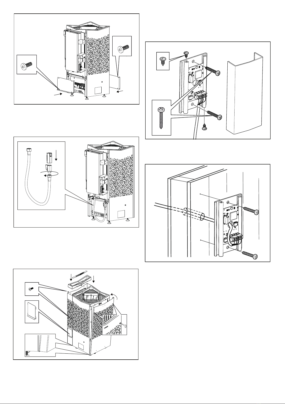
Planering av installation
Innan du påbörjar monteringen av bastuaggregatet bör du:
• Planera bastuaggregatets placering (se Avsnittet Aggregatets
placering - normalmontage, g 3).
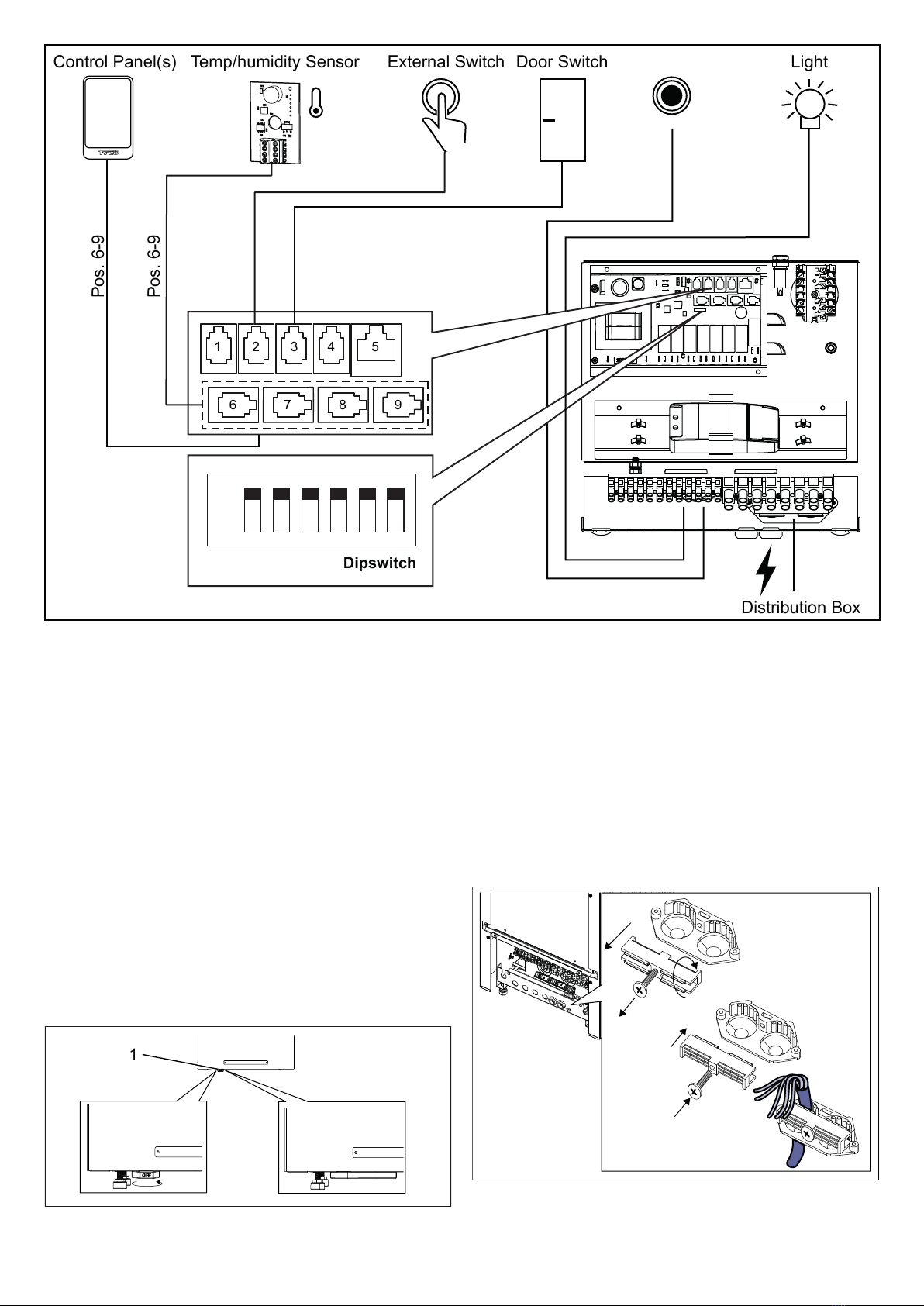
• Planera manöverpanelens placering (se medföljande anvis-
ning för manöverpanel för tillåten placering). Se även Avsnit-
tet Manöverpanelens placering, g 5.
• Planera sensorns placering (se Fig 3 samt Fig 4).
• Placera inluftsventilen (se Avsnittet Inluftsventilens placering,
g 6).
• Placera utluftsventilen (se Avsnittet Utluftsventilens placering,
g 6).
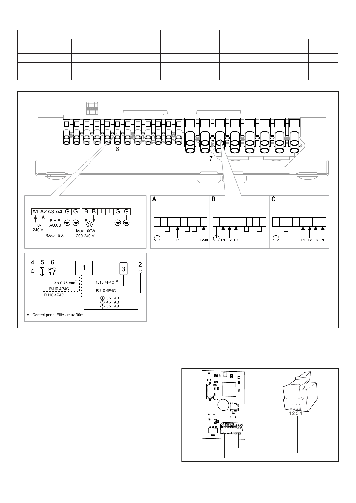
• Planera elinstallationen (se Avsnittet Anslutning/kopplings-
chema, Fig 18).
NOTERA! En glas- eller stenvägg utan värmeisole-
ring ökar föruppvärmningstiden. Varje kvadratmeter
av oisolerad tak- eller väggyta motsvarar ett tillägg på
1–2 m³ till bastuns volym.
3
2
1
4
9
6
5
7
19
17
16
20
21
11
22
12
13
18
10
14
Elite
15
23
8
FARA! Felaktig ventilation eller felaktig placering
av aggregat kan under vissa betingelser medföra
torrdestillation med risk för brand!
FARA! Otillräcklig isolering av basturummet kan
medföra risk för brand!
FARA! Användning av felaktiga material i bastu-
rum, som t.ex. spånplatta, gips o.s.v. kan medföra
risk för brand!
FARA! Anslutning av aggregatet skall utföras av
behörig elektriker enligt gällande föreskrifter!
Tabell 1: Eekt och bastuvolym
Eekt kW Bastuvolym min/max m³
6,6 4-8
8 6-12
10,5 10-18
Krav för installation
För säker användning av aggregatet, kontrollera att följande krav
tillgodoses:
• Kabel (EKK) eller elrör (Fk) för anslutning av aggregatet dras
på utsidan av värmeisoleringen.
• Kabeldragningarna ska vara korrekt utförda (se Avsnittet An-
slutning/kopplingsschema, Fig 18).
• Säkringens storlek (A) och strömkabelns storlek (mm²) ska
passa aggregatet (se Avsnittet Anslutning/kopplingsschema,
sidan Fig 18).
• Ventilation av bastu ska utföras enligt instruktioner i denna
manual (se Avsnittet Inluftsventilens placering, g 6, Avsnittet
Utluftsventilens placering, g 6).
• Placering av bastuaggregat, manöverpanel och sensor ska
ske enligt instruktionerna i denna manual.
• Aggregatets eekt (kW) ska vara anpassat till bastuns volym
(m³) (se Tabell 1). Minimivolymen får inte underskridas och
maximivolymen får inte överskridas.

3
1
3
2
4
5
Fig 2: Schematisk översikt av installation
1. Bastuaggregat
2. Manöverpanel
3. Sensor
4. Extern on/o-brytare (tillval, dörrkontakt krävs för funktion)
5. Dörrkontakt
Aggregatets placering - normalmontage
FARA! Det är ej tillåtet att montera mer än ett
bastuaggregat i samma basturum.
Placera bastuaggregatet:
• vid samma vägg som dörren (endast i undantagsfall på sido-
väggen, men då mycket nära dörrväggen).
• på säkert avstånd till golvet, sidoväggar och inredning (se Fig
3).
Placera sensorn enligt bilden (se Fig 3).
Om väggen på vilken sensorn ska installeras är gjord av mycket
värmeabsorberande material (t.ex. betong, tegel m.m.) eller om
väggen är gjort av härdats glas, kan sensorn placeras i taket med
avstånd från aggregatet enligt Fig 4.
4
7
10
9
2
6
8
3
1
5
3
Fig 4: Takmontering av sensorn
1. 300 mm
1
1
Fig 3: Placering av bastuaggregatet - normalmontage
1. Minsta avstånd till sidovägg: 50 mm
2. Sensorns placering alt 1: 300 mm från aggregat
3. Sensor
4. Minsta avstånd bakre vägg: 50 mm
5. Sensorns placering alt 2: 300 mm från aggregatets front
6. Sensorns placering: 150 mm från tak
7. Minsta avstånd till inredning: 50mm
8. Minsta takhöjd: 1900 mm
9. Minsta avstånd: 20 mm
10. Minsta avstånd till inredning: 30 mm
Manöverpanelens placering
Placering utanför basturum rekommenderas om möjligt på grund
av lägre omgivningstemperaturer.
Manöverpanelen är tillåten att placeras inne i ett Tylö basturum
alternativt egenbyggt basturum vars ventilation är utförd och
fungerar enligt Tylö förespråkad ventilation (självdragsprincip).
Läs avsnitten Inluftventilens och Utluftsventilens placering i denna
anvisning. Manöverpanelen skall alltid placeras utanför basturum-
met om inte dessa krav är uppfyllda.
Vid placering inne i basturummet så ska manöverpanelen monte-
ras med hänsyn till säkerhetsavstånd och monteringshöjd, se Fig
5.
Fig 5: Säkerhetsavstånd/monteringshöjd manöverpanel
1. Aggregat
2. Manöverpanel
3. Max 800 mm
4. Min 300 mm
2
4
3
1
VARNING! Vid felaktigt utförd ventilation riskerar
monterad manöverpanel inne i basturum att ut-
sättas för högre temperatur än tillåten och kan bli
deformerad eller gå sönder. Omgivningstempera-
tur för manöverpanel får aldrig överstiga 80°C.

4
Inluftsventilens placering
Placera inluftsventilen rakt genom väggen mitt under aggregatet.
Ventilstorlek för en familjebastu ca. 125 cm².
Dörrens luftcirkulation skall samarbeta med varmluften från ag-
gregatet.
Fig 6: In- och utluftsventilens placering
1. Inluftsventilens placering.
2. Utluftsventilens placering genom bastuvägg.
3. Utluftsventilens placering genom tomrum.
4. Utluftsventilens placering via trumma.
Utluftsventilens placering
Placera utluftsventilen:
• med maximalt avstånd till inluftsventilen, t.ex. i diagonal (se
Fig 6).
• högt på väggen eller i taket (se Fig 6).
• så att den utmynnar till det utrymme som dörr och inluftsven-
tilmynnar till.
Utluftsventilen ska ha samma area som inluftsventilen.
Tillse att in-, och utluftsventilen är öppen.
Mekaniskt ventilation rekommenderas ej p.g.a. risk för felaktig
luftväxling som kan påverka aggregatets temperaturskydd nega-
tivt.
1
2
3
4
INSTALLATION
Installation av bastuaggregat
1. Placera aggregatet så att luckan på vänster sida är åtkomlig
för att underlätta tömning av vattentanken efter bad.
FARA! Utluftsventil skall ej mynna ut i det fria.
Detta kan påverka aggregatets temperaturskydd
då ventilationsriktningen kan bli omvänd.
FARA! Eventuellt tomrum ovanför bastutaket får
ej vara helt inneslutet, utan måste ha minst ett
ventilhål på samma vägg som bastudörren!
x2
Fig 7: Orientering av aggregat
2. Ta bort fronten och främre inkopplingsluckan (se g 8).
Fig 8: Lossa de dolda skruvarna, torx 20. Lossa främre inkopp-
lingsluckan.

5
1.
1.
2.
2.
x2
1.
2.
Aggregatet ansluts med vanlig standardledning (Fk eller EKK),
godkänd för fast installation.
Eventuell enkelledare (Fk) skyddas i elrör (VP) fram till aggrega-
tet.
5. Anslut elkabeln (se Fig 11) enligt kopplingsschema (se Fig.
18).
VARNING! Se alltid till att aggregatet ansluts med
rätt huvudspänning/fasspänning!
Fig 9: Lossa de 6 st skruvarna för att ta bort bakstycket.
4. Flexa ut sidorna och lyft av bakstycket (se 1. g 10). Lossa
luckan för att kunna koppla in aggregatet. (se 2. g 10)
Fig 10: Ta bort bakstycket och bakre inkopplingsluckan.
6. Dra kablar för manöverpanel och temperatursensor genom
kabelgenomföringarna se g 11. Anslut manöververpanelens
kabel i en av de fyra RS485-kontakterna (position 6-9, se Fig
20).
7. Anslut temp/fuktsensor kabeln i position 6-9, se g 20. Dra ut
lådan för att sträcka kablarna och spänn dragavlastningar
na (se g 12).
8. Anslut eventuell kabel till belysning / aux, se Fig 11, enligt
kopplingsschema Fig 18.
9. Skjut in lådan, montera tillbaka främre och bakre inkopplings
luckorna och skruva fast dem (se 13).
1
2
3
7
8
4
6
11
5
9
10
Fig 11: Eldosan
1. Elkabel
2. Plint för inkoppling av elkabel
3. 16 mm Knockouts (x4)
4. Manöverpanelens kabel
5. Modularkontakter för inkoppling
av manöverpanel, sensor etc.
6. Sensorns kabel
7. Eventuell belysningskabel
8. Plint för eventuell inkoppling
av belysning + AUX
9. Dragavlastning för kablar till
modularkontakter (x2)
10. Dragavlastning för elkabel
11. Skyddsslang för RJ10 kablar
Fig 12: Dra ut lådan för lättare åtkomst
3. Lossa först de bakre två skruvarna som håller locket till tan-
ken, och lyft upp (se 1. g 9). Lossa skruvarna på sidorna (se
2. g 9).

6
14. Montera sensorn på väggen se Fig 16. Termistorledningen
kan även dras igenom väggen. Täta eventuella hål
i väggen bakom sensorn, se Fig 17. Termistorledningen kan
förlängas utanför bastun med svagströmsledning
(4-ledare).
Fig 16: Montering av sensorn, Kabeln
inne i bastun måste vara värmebeständig. Anslut sensorns kabel
(se Fig 19).
Fig 17 : Ledningsdragning genom vägg.
Combi Elite
Ovanliga spänningar/fas-tal
Vid inkoppling till spänningar eller fas-tal, som inte anges i kopp-
lingsschema Fig 18, kontakta Tylö kundservice.
Extern ON/OFF-brytare (tillval)
Extern ON/OFF-brytare placeras på valfri plats utanför bastun.
Brytare fungerar med både impuls eller konstant slutning.
Kretskortet i aggregat känner automatiskt av vilken slutning som
används. Möjlighet nns att se aggregatets status och fel på
dörrkontakt ifall brytare har inbyggd led. Se instruktioner som
medföljer externbrytaren.
Dörrkontakt
Dörrkontakt är ett krav för att kunna använda Elite-panelens
kalenderfunktion samt fjärrstyra bastun via externbrytare, mobil-
applikation eller PC-applikation.
Se instruktioner som medföljer dörrkontakten.
x6
10. Montera slangen genom att skruva fast ventilen, trycka på
pipen och skruva på den på tanken (se g 14)
13. För att säkerhetsställa att aggregaten står stadigt, justera föt-
terna och lägg på en klick silikon och sätt aggregatet på plats
Fig 14: Montera tömningsslangen
11. Haka tillbaka front och bakstycke och fäst dem med sina
skruvar (se g 15)
12. Montera locket till vattentanken och fäst med de två skruvar-
na och haka på tömningsluckan på sidan.
Fig 13: Montera tillbaka luckorna bak och fram.
x2
x2
Fig 15: Montera på front, bakstycke, locket till tanken och töm-
ningslucka

7
ANSLUTNING/KOPPLINGSSCHEMA
TAB 400-415 V 3N~ (C) 200-208 V 3~ (B) 230 V 3~ (B) 200-208 V~ (A) * 230-240 V~ (A) *
Eekt
kW
Strömstyr-
ka amp
Lednings-
area mm²
Strömstyr-
ka amp
Lednings-
area mm²
Strömstyr-
ka amp
Lednings-
area mm²
Strömstyr-
ka amp
Lednings-
area mm²
Strömstyr-
ka amp
Lednings-
area mm²
6,6 10 1,5 (g 22) 19 4 17 4 33 10 29 10
8 12 2,5 23 6 20 4 40 16 35 10
10,8 16 2,5 32 10 28 10 - - - -
* 10,8kW är inte godkänd för enfas i Europa
Fig 18: Kopplingsschema
Fig 19: Inkoppling av fukt- och tempsensor - Combi Elite
R=Röd, G=Grön, W=Vit, B=Svart
1
6
5
4
3
2
7
RJ10 4P4C
3 x 0.75 mm
2
RJ10 4P4C
RJ10 4P4C
RJ10 4P4C
Control panel Elite - max 30m
*
*
6,6-8,0 kW
200-240 V 1N~/2~
1234567G
6,6-8,0-10,5 kW
200-230 V 3~
6,6-8,0-10,5 kW
400-415 V 3N~
6
G
G
A1
A2
A3
A4
B
G
G
I
I
B
AUX 0
*
0-
240 V~
Max 100W
200-240 V~
*Max 10 A
1234567G 1234567G
1
2
3
4
B
A
11
12
R
G
W
B
1. Aggregat
2. Sensor (ansluts till pos 6-9)
3. Manöverpanel (ansluts till pos 6-9)
4. Externbrytare (tillval)
5. Dörrkontakt
6. Plint för inkoppling av belysning och Aux
7. Plint för inkoppling av elkabel

8
Light
Distribution Box
Control Panel(s)
Door Switch
Pos. 6-9
Pos. 6-9
External Switch
On
Off
CTS
1 2 3 4 5 6
Sauna Combi
Factory settings
Dipswitch
1
2
6
7
8
9
3
4
5
Temp/humidity Sensor
%
AUX 0
Fig. 20. Schematisk installation Crown Combi Elite
EGENKONTROLL AV INSTALLATION
För att kontrollera installationen:
1. Slå på huvudspänning till aggregat från elcentral.
2. Slå på brytaren längst ned på aggregatet, se g 21.
3. Försäkra dig om att manöverpanelen lyser, kan ta en minut.
4. Starta aggregatet (se Bruksanvisning). Belysningen tänds.
5. Kontrollera att alla de tre rörelementen går igång (blir röda),
kan ta 5 min.
ON
OFF
1
Fig. 21 ON / OFF
1.
2.
3.
Fig. 22: Dragavlastning - När 5x1.5 mm² kabel används
1. Skruva ur skruven och vänd låsbiten
2. Montera tillbaka
3. Spänn fast kabeln

9
NOTERA! Vid ändring av modularkablage, t. ex.
förkortning av ledning, krävs en crimptång.
1
2
3
4
Pin:
1
2
3
4
Pin:
1
2
3
4
1
2
6
7
8
9
3
4
5
Cable
Solid conductor
Cable
Stranded conductor
Max. Ø3,6mm
OK!
Fig. 22 Modularplugg/modularkontakt, reläkort och ledare ertrådig
1. Modularplugg RJ10, används till kabel (max. kabelarea för kontaktering av modularplugg: 0,14-0,20 mm² / AWG26-AWG24)
2. Modularjack RJ10, sittter monterad på reläkort och manöverpanel
3. Reläkort (Pos. 6-9 vita är anslutningar)
4. Kabel/ledare som ansluts till modularplugg skall vara ertrådig
Beskrivning av kablage/modularkontakter
Tabell 3: Beskrivning av reläkortets anslutningar
Pos Enhet Använd
pin Anmärkning Pin1 Pin 2 Pin 3 Pin 4
1 - NTC Tempsensor i rum 2, 3 10kΩ. Kan även kopplas
in på pos 4 - SEC/NTC. Not use 10kΩ 10kΩ Not use
2 - EXT
SWITCH
Externbrytare 3, 4 Start/stopp av drift. Kon-
stant eller impulsslutning. Not use Not use Switch Switch
Externbrytare med led-indikering 2, 3, 4
Start/stopp av drift.
12VDC max 40mA.
Tylö artikel nr: 90908048
Not use Led GND Switch Switch /
Led 12V
3 - DOOR
SWITCH
Dörrkontakt (NO) 3, 4 Tylö artikel nr: 90908035 Not use Not use Switch Switch
Dörrkontakt (NO) med extern
larm-indikering 2, 3, 4
12VDC max 40mA. Krävs
extern kopplingsbox,
saluförs inte.
Not use Led GND Switch Switch /
Led 12V
4 - SEC/NTC
Kombinerad
tempsensor/
tempskydd i rum
Tempsensor
10kΩ 2, 3 Används endast till vissa
produkter. Sec 10kΩ 10kΩ Sec
Tempskydd
130°C 1, 4
Adapter för aktivering av drift-
status 1, 4 Steam Commercial Sec Not use Not use Sec
5 - ADD-ON Extra reläkort 1, 2, 3, 4,
5, 6, 7, 8
Obs! Ej för nätverksan-
slutning.
6-9 - RS485
Manöverpaneler 1, 2, 3, 4 Tylö Elite och Pure manö-
verpanel. A (RS485) B (RS485) 12V GND
Temp/fuktsensor % 1, 2, 3, 4
Combiaggregat med
Elite manöverpanel och
Tylarium.
A (RS485) B (RS485) 12V GND
Synkkabel A/B 1, 2
Multisteam och Tylarium.
Primär och sekundär
enhet.
A (RS485) B (RS485) Not use Not use
Denna bruksanvisning bör sparas!
Vid eventuella problem, kontakta inköpsstället.
© Eftertryck, helt eller delvis, är förbjudet utan Tylös skriftliga tillstånd. Rätt
till ändringar i material, konstruktion och design förbehålls.

10
WARNING!
• Poor ventilation or heater positioning may lead to dry distillation, posing a re risk under certain circum-
stances!
• Insucient insulation of the sauna cabin may pose a re risk!
• Use of the wrong materials in the sauna cabin, such as particle board, drywall, etc., may pose a re risk!
• The heater must be connected by a qualied electrician pursuant to applicable regulations!
• No more than one heater may be installed in the same sauna cabin.
• The air exhaust vent must not lead outdoors. This could cause the ventilation direction to be reversed,
which may negatively aect the heater temperature cut-out.
• Any gap above the sauna ceiling should not be sealed without leaving at least one vent hole on the same
wall as the sauna door!
• Always check that the heater is connected to the correct main/phase voltage!
• Anyone with a mental or physical disability or little experience or knowledge of how to use the equipment
(e.g. children) must be instructed or supervised by someone responsible for their safety.
• Touching the upper parts of the heater may cause burn injuries. Tylö recommends always using the heat-
er screen.
• Never allow children to play near the heater!
• Saunas are not recommended for people in poor health. Please consult a doctor.
• Fragrant essences and similar products may ignite, if poured directly onto the stones.
• Covering the heater may cause a re.
• Never put fragrances in the herb bowl or water reservoir.
• If the stone compartment lls up with gravel and small stones, the tubular element can be damaged as a
result of overheating, as air ow will be insucient.
• The sauna room or cabin is to be inspected before either restarting the timer or by switching on the appli-
ance by a separate remote-control system
• The sauna room or cabin is to be inspected before setting the appliance to a standby mode for a delayed
start
• Thermostat sensors have to be installed so that they are not inuenced by incoming air
• The door of the sauna room or cabin is tted with an interlock such that the stand-by mode setting for
remote operation is disabled if the sauna door or cabin door is opened when the stand-by mode setting
for remote operation is set
• Means for full pole disconnection must be incorporated in the xed wiring in accordance with the wiring
rules
• This appliance can be used by children aged from 8 years and above and persons with reduced physical,
sensory or mental capabilities or lack of experience and knowledge if they have been given supervision
or instruction concerning use of the appliance in a safe way and understand the hazards involved
• Children shall not play with the appliance
• Cleaning and user maintenance shall not be made by children without supervision

11
PRIOR TO INSTALLATION
Parts
Check that the following parts are included in the packaging:
Figure 1: Sauna heater/control panel parts
1. Sauna heater x 1
2. Herb Strainer x 1
3. Hose x 1
4. Valve x 1
5. Emptying spout x 1
6. Warning sticker in ten languages x 1
7. Connectors x 3
8. Emptying Hatch x1
9. Screw B4x6,5 x 2
10. Clips TC (3-5) x 10 pieces
11. Plastic plugs 25x5 x 2 pcs
12. Screws B6x25 x 2 pcs
13. Humidity- and temperature sensor and Cover
14. Cable between heater and humidity- and temperature sensor,
RJ10 4P4C, cable length 4 m x 1 pce
15. Control panel Elite
16. Cable between heater and control panel, RJ10 4P4C, cable
length 5 m x 1 pce
17. Cable tie
18. Clips C3x5 x 10 pieces
19. Modular plug 4, 4/4RJ10 x 2
20. Plastic plugs 25x5 x 2 pcs
21. Screws B6x25 x 2 pcs
22. Protection hose Ø14x150 mm x 3 pcs, for RJ10 cables (sensor,
control panel, door switch)
23. Door contact (Combi Elite)
24. Sauna fragrance x 1
Contact your dealer if anything is missing.
Control panel Pure is supplied with Sense Combi Pure.
Control panel Elite is supplied with Sense Combi Elite.
See separate guides.
Installation tools
The following tools and materials are needed for installation and
connection:
• water level,
• adjustable spanner,
• electric drill,
• screwdrivers.
Installation planning
Before starting to install your sauna heater:
• Plan the sauna heater positioning (see the Heater positioning
- normal installation section, Figure 3).
• Plan the control panel positioning (see the attached instruc-
tions for the control panel for allowable positioning). See also
the Control Panel section, Figure 5.
• Plan the sensor positioning (see Figure 3 and Figure 4).
• Position the air intake vent (see the Air intake vent positioning
section, Figure 6).
• Position the air exhaust vent (see the Air exhaust vent posi-
tioning section, Figure 6).
• Plan the electrical installation (see the Connection/wiring
diagram section, Figure 18).
NOTE! A glass-, or brick wall without heat insulation
increases the warm-up time. Each square meter of
uninsulated ceiling or wall surface equals an addition-
al 1–2 m³ of sauna volume.
3
2
1
4
9
6
5
7
19
17
16
20
21
11
22
12
13
18
10
14
Elite
15
23
8
DANGER! Poor ventilation or heater positioning
may lead to dry distillation, posing a re risk
under certain circumstances!
DANGER! Insucient insulation of the sauna
cabin may pose a re risk!
DANGER! Use of the wrong materials in the
sauna cabin, such as particle board, drywall, etc.,
may pose a re risk!
DANGER! The heater must be connected by a
qualied electrician pursuant to applicable regu-
lations!
Table 1: Output and sauna volume
Output kW Sauna volume min./max. m³
6,6 4-8
8 6-12
10,5 10-18
Installation requirements
To ensure safe use of the heater, check that the following criteria
are met:
• Cable (EKK) or electrical ducting (Fk) for connecting the
heater must be run on the outside of the heat insulation.
• The cables must be installed correctly (see the Connection/
wiring diagram section, Figure 18).
• The fuse size (A) and the power cable size (mm²) must be
suitable for the heater (see the Connection/wiring diagram
section, Figure 18).
• The sauna ventilation must comply with the instructions in
this manual (see the Air intake valve positioning section, Fig-
ure 6, the Air exhaust valve positioning section, Figure 6).
• The position of the sauna heater, control panel and sensors
must comply with the instructions in this manual.
• The heater's output (kW) must be adapted to the sauna's vol-
ume (m³) (see Table 1). The minimum and maximum volumes
must not be exceeded.

12
1
3
2
4
5
Figure 2: Schematic diagram of installation
1. Sauna heater
2. Control panel
3. Sensor
4. External on/o switch (option, door contact needed for func-
tion)
5. Door contact
Positioning the heater - normal installation
DANGER! No more than one heater may be in-
stalled in the same sauna cabin.
Position the sauna heater:
• on the same wall as the door (or the side wall if very close to
the door wall).
• Position the heater at a safe distance from the oor, side
walls and interior ttings (see Figure 3).
Position the sensor according the picture (see Figure 3).
If the wall on which the sensor is to be installed is made of highly
heat-absorbing material (e.g. concrete, brick, etc.), or of hardened
glass, the sensor may be installed in the ceiling at a distance from
the heater, according to Figure 4.
4
7
10
9
2
6
8
3
1
5
3
Figure 3: Positioning the heater - normal installation
1. Minimum distance from side wall: 50 mm
2. Sensor position alt 1: 300 mm from heater
3. Sensor
4. Minimum distance from back wall: 50 mm
5. Sensor position alt 2: 300 mm from heater front
6. Sensor position: 150 mm from ceiling
7. Minimum distance from interior ttings: 50 mm
8. Minimum ceiling height: 1900 mm
9. Minimum distance: 20 mm
10. Minimum distance from interior ttings: 30 mm
Figure 4: Sensor installation on ceiling
1. 300 mm
1
1
Figure 5: Safety distance / installation height, control panel
1. Heater
2. Control panel
3. Max. 800 mm
4. Min. 300 mm
2
4
3
1
Placement of the control panel
Where possible, placement of the control panel outside the sauna
room is recommended due to lower ambient temperatures.
The control panel may be placed inside a Tylö sauna room or
a self-built sauna room with correct ventilation which operates
according to Tylö-recommended ventilation (natural ventilation
principle). Read the sections titled, Positioning the intake vent and
Positioning the outlet vent in these instructions. The control panel
must always be placed outside the sauna cabin if these require-
ments are not met. If installing the control panel inside the sauna
cabin, it should be positioned with regard to safety distances and
installation height, see Figure 5.
WARNING! With incorrect ventilation, a con-
trol panel tted inside the sauna cabin may be
exposed to excessive temperatures, which can
cause the control panel to become deformed or
defective. The ambient temperature around the
control panel should never exceed 80°C.

13
Positioning the inlet vent
Install the inlet vent straight through the wall under the center line
of the heater.
Vent size for a family sauna approx. 125 cm².
The air circulation from the door must concord with the hot air
circulation from the heater.
Figure 6: Positioning the air intake and exhaust vents
1. Inlet vent position.
2. Outlet vent position through the sauna wall.
3. Outlet vent position through the cavity.
4. Outlet vent position via duct.
Positioning the outlet vent
Position the outlet vent
• at the maximum possible distance from the air intake vent,
e.g. diagonally (see Figure 6).
• high on the wall or in the ceiling (see Figure 6).
• so that it vents into the space that the door and air intake
vent open into.
The outlet vent must have the same area as the inlet vent.
Ensure that the inlet and outlet vent are open.
Mechanical ventilation is not recommended due to the risk of poor
air exchange, which can negatively aect the heater temperature
cut-out.
1
2
3
4
INSTALLATION
Sauna heater installation
1. Place the heater so the hatch on the left side is free to make
it easier to emptying the tank after use.
DANGER! The air exhaust vent must not lead out-
doors. This could cause the ventilation direction
to be reversed, which may negatively aect the
heater temperature cut-out.
DANGER! Any gap above the sauna ceiling
should not be sealed without leaving at least one
vent hole on the same wall as the sauna door!
Figure 7: Orientation of the heater
2. Lift of the front panel and front hatch, see Figure 8.
x2
Fig 8: Undo the hidden screws, torx 20, take of the front panel
and the lower hatch

14
Connect the heater using standard wiring (Fk or EKK) approved
for xed installation.
Any single wires (Fk) must be protected in electrical conduits (VP)
to the heater.
5. Connect the electrical cable (see Figure 11) according to the
wiring diagram (see Figure 18).
WARNING! Always check that the heater is con-
nected to the correct main/phase voltage!
6. Run the cables for the control panel and the temperature
sensor through the cable grommets (see Figure 11). Connect
the control panel cable to one of the four RS485 contacts
(positions 6-9) (see Figure 20).
7. Connect the humidity- and temperature sensor
cable (positions 6-9)(see Figure 20). Pull out the drawer
to stretch the cables and tighten the strain relieves
(see Figure 12).
8. Connect the light / Aux cable , see Figure 10, according to the
wiring diagram Figure 18 (if relevant)
9. Push back the drawer, mount the front and back hatch and
tighten the screws, (see Figure 13)
Figure 11: Electrical compartment
1. Electrical cable
2. Terminal for connection of
electrical cable
3. 16 mm Knock outs
4. Control panel cable
5. Modular contacts for connec-
tion of control panel, sensor
etc.
6. Sensor cable
7. Light cable (if relevant)
8. Terminal for connection of light
+ Aux (if relevant)
9. Strain relief connector for ca-
bles to modular contacts (x2)
10. Strain relief connector for
electrical cable
11. Protection hose for RJ10
cables
1.
1.
2.
2.
x2
1.
2.
Fig 9: Undo the 6 screws to remove the back cover.
4. Flex out the sides and remove the back cover (see 1 in Figure
10). Remove the lower hatch (see 2 in Figure 10).
Fig 10: Remove the back cover and the lower hatch.
3. Undo the two screws on the back, remove the cover to the
water reservoir (see 1 in Figure 9) Undo the screws on the
sides. (see 2 in Figure 9).
3. Lossa först de bakre två skruvarna som håller det lilla gallret,
och lyft upp (se 1. g 9). Lossa skruvarna på sidorna (se 2.
g 9).
1
2
3
7
8
4
6
11
5
9
10
Figure 12: Pull out the drawer for easier access.

15
Unusual voltages/numbers of phases
Contact Tylö Customer Service before connecting to voltages or
numbers of phases that are not listed in the wiring diagram Figure
18.
External ON/OFF switch (option)
External ON/OFF switch can be installed anywhere outside the
sauna. The switch works for impulse or constant deactivation.
The heater circuit automatically recognizes which is used. Heater
status and faults on the door contact can be seen if the switch has
a built-in LED.
See instructions supplied with the external switch.
Door contact
The door contact is necessary to be able to use the Elite panel’s
calendar function, plus remote control the sauna via external
switch, mobile or PC apps.
See instructions supplied with the door contact.
x2
x2
Combi Elite
Fig 15: Mount the front and back cover, the cover to the water
reservoir and the emptying hatch
x6
Figure 13: Put back the front and back hatch
10. Mount the emptying hose, tighten the valve, click in the spout
and tighten the hose on the water reservoir (see Figure 14).
13. To make sure the heater stands stable, adjust the feet, apply
some silicone and put it into place.
Fig 14: Mounting of the emptying hose
11. Put back the front and back cover and tighten the screws,
see Figure 15.
12. Put back the cover to the water reservoir, tighten the screws
and hook on the water drain hatch.
Figure 14: Installing the sensor, wiring through the wall
14. Install the sensor on the wall see Figure 16. The thermistor
wire may also be passed through the wall. Seal any holes in
the wall behind the sensor, see gure 17. The thermistor wire
may be extended outside the sauna using low voltage wire
(2-, 4-lead).
Fig 16: Installing the humidity- and temperature sensor. The cable
inside the sauna must be heat resistant. Connect the sensor
cable (see Figure 19).

16
CONNECTION/WIRING DIAGRAM
TAB 400-415 V 3N~ (C) 200-208 V 3~ (B) 230 V 3~ (B) 200-208 V~ (A) * 230-240 V~ (A) *
Output
kW
Amperage
amp
Conductor
area mm²
Amperage
amp
Conductor
area mm²
Amperage
amp
Conductor
area mm²
Amperage
amp
Conductor
area mm²
Amperage
amp
Conductor
area mm²
6,6 10 1,5 (g 22) 19 4 17 4 33 10 29 10
8 12 2,5 23 6 20 4 40 16 35 10
10,8 16 2,5 32 10 28 10 - - - -
* 10,8 kW is not approved for singel phase in Europe
Figure 18: Wiring diagram
1. Heater
2. Humidity- and temperature sensor - Combi Elite
3. Control panel
4. External switch (option)
5. Door contact
6. Light/terminal for connection of light
7. Terminal for connection of power cable
1
6
5
4
3
2
7
RJ10 4P4C
3 x 0.75 mm
2
RJ10 4P4C
RJ10 4P4C
RJ10 4P4C
Control panel Elite - max 30m
*
*
6,6-8,0 kW
200-240 V 1N~/2~
1234567G
6,6-8,0-10,5 kW
200-230 V 3~
6,6-8,0-10,5 kW
400-415 V 3N~
6
G
G
A1
A2
A3
A4
B
G
G
I
I
B
AUX 0
*
0-
240 V~
Max 100W
200-240 V~
*Max 10 A
1234567G 1234567G
Fig 19: Connecting the humidity- and temperature sensor -
Combi Elite
R=Red, G=Green, W=White, B=Black
1
2
3
4
B
A
11
12
R
G
W
B

17
Light
Distribution Box
Control Panel(s)
Door Switch
Pos. 6-9
Pos. 6-9
External Switch
On
Off
CTS
1 2 3 4 5 6
Sauna Combi
Factory settings
Dipswitch
1
2
6
7
8
9
3
4
5
Temp/humidity Sensor
%
AUX 0
Figure 20. Schematic diagram of installation Crown Combi Elite
ON
OFF
1
Figure 21 ON / OFF
SELF-INSPECTION OF THE INSTALLATION
To check the installation:
1. Switch on the mains supply to the heater from the distribution
board.
2. Switch on the heater, use the lever, see gure 21
3. Check that the control panel lights up, takes approx. 1 minute
4. Start the heater (see User guide). The light turns on.
5. Check that all three tubular elements start to heat up (go
red), takes approx.5 minutes.
1.
2.
3.
Figure 22: Cord anchorage - When use of 5x1.5 mm² cable
1. Unscrew and turn the lock piece
2. Mount it back
3. Tighten the cable

18
Please keep these instructions!.
In the event of problems, please contact the retailer where you purchased
the equipment.
© This publication many not be reproduced, in part or in whole, without
the written permission of Tylö. Tylö reserves the right to make changes to
materials, construction and design.
Description of cabling/modular contacts
NOTE! Crimp pliers are needed if changing modular
cabling, e.g. shortening wires.
1
2
3
4
Pin:
1
2
3
4
Pin:
1
2
3
4
1
2
6
7
8
9
3
4
5
Cable
Solid conductor
Cable
Stranded conductor
Max. Ø3,6mm
OK!
Figure 22. Modular plug/modular contactor, relay board "high" and multi-threaded lead
1. Modular plug RJ10, used with cable (max. cable cross-section for connection of modular plug: 0.14-0.20 mm² / AWG26-AWG24)
2. Modular jack RJ10, connected to relay board and control panel
3. Relay board "high" (Pos. 6-9 white connectors)
4. Cable/lead connected to the modular plug must be multithreaded
Table 3: Description of relay board connections
Pos Unit Use pin Comment Pin1 Pin 2 Pin 3 Pin 4
1 - NTC Temp. sensor in the room 2, 3
10kΩ. May also be con-
nected at Pos 4 - SEC/
NTC.
Not use 10kΩ 10kΩ Not use
2 - EXT
SWITCH
External switch 3, 4
Start/stop operation.
Constant or impulse
deactivation.
Not use Not use Switch Switch
External switch with LED indica-
tion 2, 3, 4
Start/stop operation.
12VDC max. 40mA.
Tylö Item no.: 90908048
Not use Led GND Switch Switch /
Led 12V
3 - DOOR
SWITCH
Door contact (NO) 3, 4 Tylö Item no.: 90908035 Not use Not use Switch Switch
Door contact (NO) with an exter-
nal alarm indication 2, 3, 4
12VDC max. 40mA.
External junction box, not
for sale.
Not use Led GND Switch Switch /
Led 12V
4 - SEC/NTC
Combined tempe-
rature sensor/cut-
out in the room
Temp. sensor
10kΩ 2, 3
Only used for certain
products. Sec 10kΩ 10kΩ Sec
Temperatu-
re cut-out
130°C
1, 4
Adapter for activation of opera-
ting status 1, 4 Steam Commercial Sec Not use Not use Sec
5 - ADD-ON Extra relay board 1, 2, 3, 4,
5, 6, 7, 8
Note: Not for network
connection.
6-9 - RS485
Control panels 1, 2, 3, 4 Tylö Elite and Pure con-
trol panels. A (RS485) B (RS485) 12V GND
Temp./Humidity sensor % 1, 2, 3, 4
Combi heater with Elite
control panel and Tyla-
rium.
A (RS485) B (RS485) 12V GND
Synchronisation cable A/B 1, 2
Multisteam and Tylarium.
Primary and secondary
units.
A (RS485) B (RS485) Not use Not use
Other manuals for CROWN COMBI ELITE
2
This manual suits for next models
1
Table of contents
Languages:
Other Tylo Electric Heater manuals
Popular Electric Heater manuals by other brands

Orbegozo
Orbegozo BP 5003 A instruction manual

Varmebaronen
Varmebaronen EK 13 Installation and Maintenance

Bromic Heating
Bromic Heating Tungsten 2000W Installation, instruction and service manual

Airelec
Airelec PREMIER SAS Digital User manual and installation guide

Rowenta
Rowenta AQUA EXCEL SO9080 manual

AKO
AKO AKO-SAFE-5M instructions