Tylo MEGA-LINE SUPER 10 User manual

12/2010
KASTOR OY TYLÖ MEGA – LINE SUPER 10 Sivu 6/22
TYLÖ MEGA-LINE SUPER 10
- Electrical Sauna Heater Manual -
1. INTRODUCTION
We thank you for your confidence in this Tylö product. Tylö heaters are known to be long lived and of high quality. We
recommend that you – and the person installing this heater – read these instructions carefully. This manual should be always
close at hand when needed. Once the installation is completed, this manual should be handed to the sauna's owner or the
person responsible for operating it. Before you do anything, you should read this manual and pay special attention to the
“WARNINGS” part on page 3. (mm) DI 10K
X (min) 195
Y (min) 260
Y (max) 305
a 165
b 320
2. INSTALLATION
2.1. The Heater's Installation Location
The manufacturer's safe installation distances (table 3,
page 5) must be adhered to. These distances are also
given on the heater's data plate. The attachment sizes for
the wall mountings are shown in picture 1a. The walls
next to the heater and the roof above it must not be
protected with additional paneling, as the temperature in
the wall material may rise to dangerous levels. This heater
is not designed to be embedded or installed in an alcove.
2.2. Attaching The Heater to The Wall
For easier installation the heater is equipped with a
detachable wall mounting (picture 1b) that can be
attached to the wall beforehand (picture 1a). You may use the included
attachment screws for installation in a wooden wall. A thin panel board
is not sturdy enough for the attachment. You should strengthen it from
the backside using board or plywood. Use heat resistant attachments
(wedge or hammerset anchors, no plastic plugs) for masonry,
brickwork or other stone walls. The heater is lifted into its place
according to pictures 1c, 1d, 1e. Do not lift the heater by its coils or
the upper plate of the back casing. Use the lower rim of the inner
casing with support from the upper part instead. A free corridor should
be left at one side of the heater for maintenance work.
2.3. Connection to The Power Grid
The heater's electrical installation must be performed by a certified electrician. Check the heater's technical data prior to
connection. The connection to the power grid may only be performed by a professional electrician who is certified according
to present regulations. The heater is connected semi-permanently to a connection box on the sauna wall. The connection cord
should be a H07RN-F (VSN, VSB) rubber cable or equivalent. Do not use cords with PVC insulation. The connection diagram
is attached to this manual (picture 7) and to the heater's connection box. Do not attach the heater's power feed to the error
current connector.
The connection is performed in the following manner before the heater is lifted into its place: 1. Remove the wall mounting in
the back of the heater, open the upper attachment screws at the sides and loosen the lower ones. 2. Attach the throughput
rubbers and cable grip. 3. Pass the cable through the throughput rubber to the connection box. 4. Attach the cable to the cable
grip and connector according to the connection diagram. 5. Provide sufficient cable length to ensure that the cable does not run
underneath the stone enclosure nor too close to the heater's base plate. The heater's connector also provides for control of the
electric heating (or the heater's signal lamp). The package holds a second throughput rubber and cable grip with screws for this
purpose. The control cable's conducting material and diameter must be equal to the connection cable. The relay used in
controlling the electric heating gets a control voltage of 230 VAC from the heater. The conductors' diameters and numbers and
fuse values are given in the technical data table. The spray water tight connection box must not be attached more than 50 cm
above the ground.

12/2010
KASTOR OY TYLÖ MEGA – LINE SUPER 10 Sivu 7/22
2.4. Installation of The Sensor And Its Location on The Wall
The sensor is attached to the sauna wall on the heater's center line. If you wish to heat the sauna to higher temperatures than
usual, the sensor may be moved to the side according to table 1 and picture 2. Deviations from the given measurements will
cause fire hazards.
Picture 2
TABLE 1
HEATER
MODEL
FROM HEATER
CENTER
ABOVE
FLOOR
C =cm A =cm cm
Super DI 10K
10kW
Min. 80
Min. 80
150
There are two alternatives for attaching the sensor to the wall. For surface attachment, the sensor's protective cover is attached to
the sauna wall (picture 3A). Attach the sensor to the cover and raise the cable grip strips at the lower part of the cover. Bend the
cable grip strips around the cable and bend the wings of the cover over the sensor (picture 3B). For embedded installation, the
sensor is attached directly to the wall (picture 3C).
Picture 3
2.5. Changing The Location of The Control Panel
The heater control panel's location may only be switched by a professional with sufficient training. The control panel has been
factory installed to be used from the front of the heater. It may be turned to point to the side of the heater in the following
manner: 1) Release the attachment screw underneath the control panel. 2) Move the rubber gaskets on the decorative piping
further away from the control panel. 3) Remove the control panel by pulling it outwards from the piping (the plastic material
used tolerates bending well). 4) The keyboard connector cable in the connection room has some slack to allow pulling the
control panel further from the piping. 5) Detach the cable at the keyboard's row connector. 6) Move the cable to the required
side and pull it through. 7) Assemble in reverse order.
3 SAUNA ROOM INSTRUCTIONS
f
3.1. The Sauna Room
The heat insulation of walls and ceiling must be sufficient, to avoid losing too much heat to the
outside. Wood is the most suitable surface material A wooden surface warms up quickly and
radiates a pleasantly even heat to the bather's skin. You should avoid masonry and other stone
surfaces in the walls, as stone takes in too much heat and would require a significantly more
powerful heater than a wooden room of the same size. One square meter of stone surface on
the wall or ceiling above the heater's level is equal to 2-3 cubic meters of additional volume in
the room. A glass door and windows have similar effects on the sizing. Log walls require an
additional 25% of added power to the volume calculated in this manner.
a
Min 500
c
b
Excessive height also adds unnecessary volume to the room. The distance between the highest
bench and the ceiling should not be too high, as the temperature decreases towards the floor. Picture 4

12/2010
KASTOR OY TYLÖ MEGA – LINE SUPER 10 Sivu 8/22
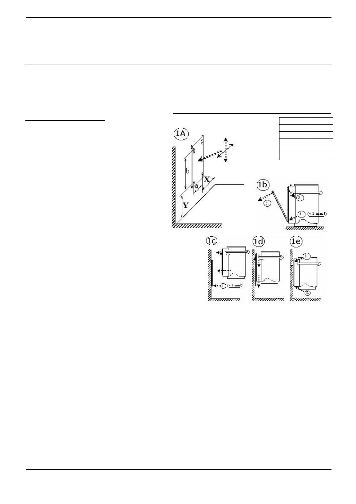
A sufficient distance from bench to ceiling is about 110-120 cm. We recommend
locating the heater as low as possible (within safety limits). The sizes of sauna rooms
are given in table 2.
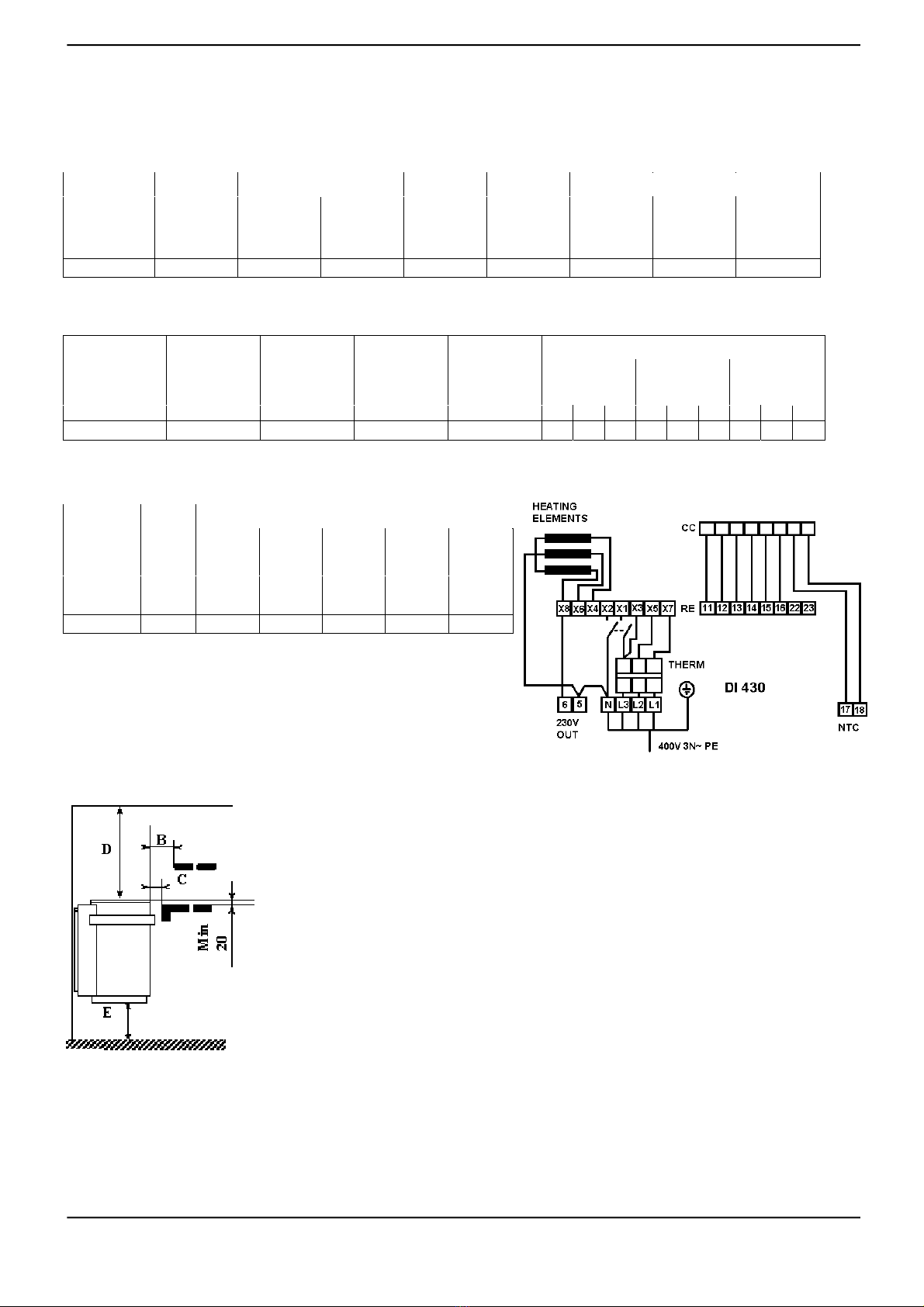
Min 500
a
e
b
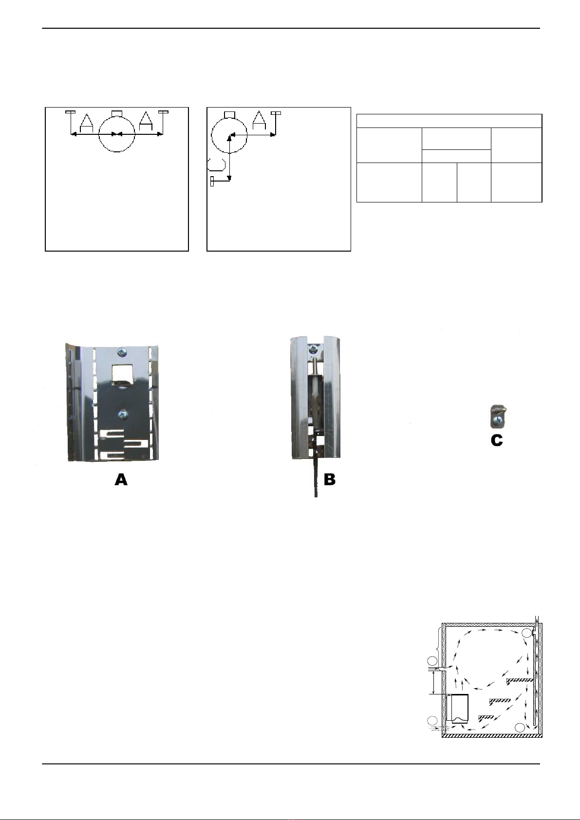
3.2. Correct Air Circulation
Sufficient air exchange in the sauna is very important. A suitable amount for a
family sauna would be about 6 times the sauna's volume per hour. Air removal
happens either through gravity (= traditional, “natural circulation”) or mechanically,
through an air removal fan.
Mechanical air circulation (pictures 4 and 5):
f
be
d
a
Fresh air is taken in (preferably from outside the house) through a 100 mm diameter
pipe that is at least 500 mm above the heater (a). The fresh air may also be piped in Picture 5
below the heater, close to the floor (b), as long as you make sure that the cool air flow does
not go straight along the floor to the exit air vent. The most important aspect in air circulation
is to ensure an efficient mixing of fresh air with heated air and the vapor from the thrown
water. The exit air vent should be preferably placed below the benches (c), as far from the air
intake as possible.
The exit air may also be fed through the washing room, e.g. underneath the door (e). The
sauna should also have a drying valve (f) behind the benches, near the ceiling. The drying
valve is closed during the heating and bathing phases and opened for the final drying out. The
circulation fan is kept running throughout the bathing and afterwards. It may be stopped for
the preheating phase.
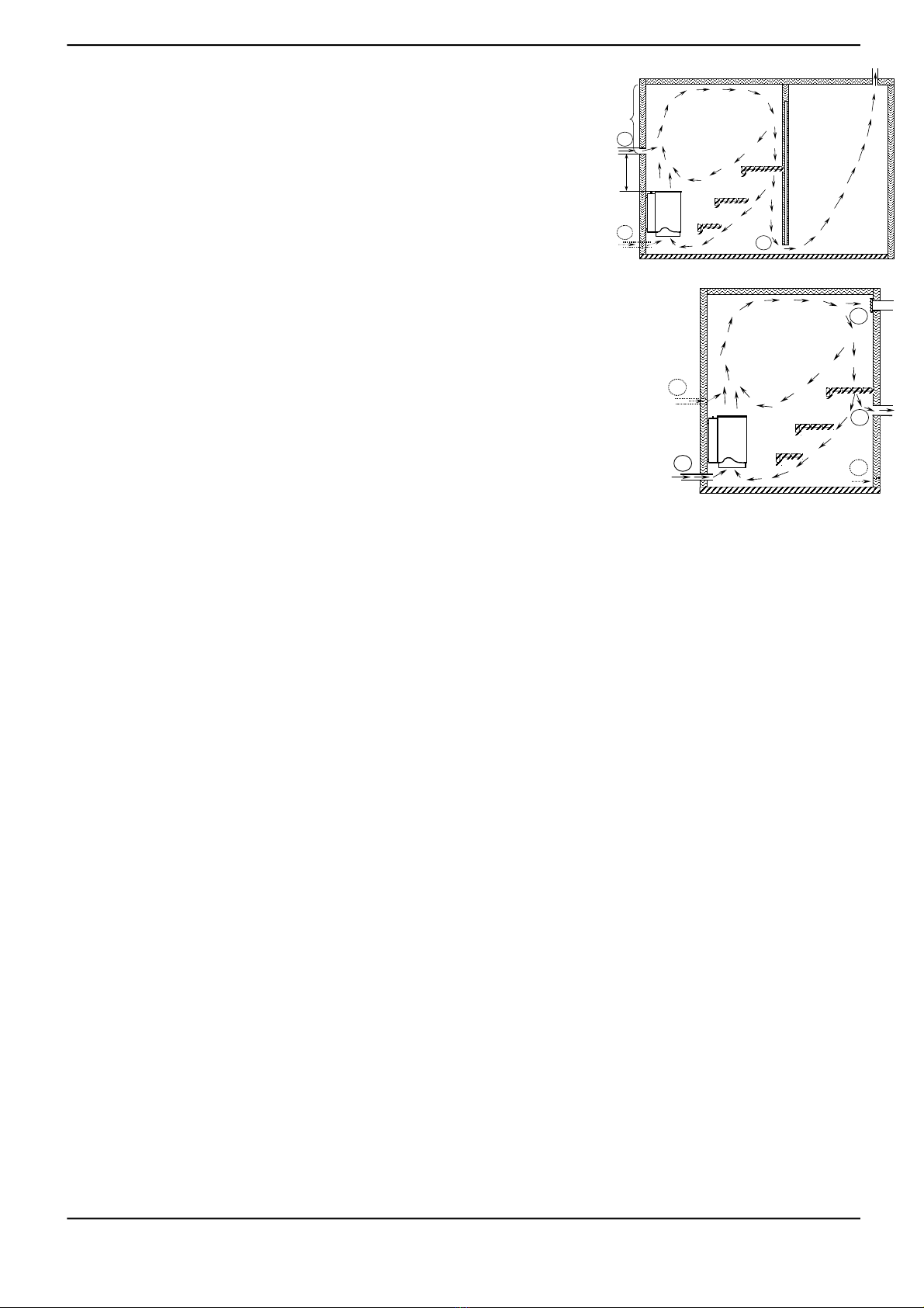
Gravity circulation – i.e. natural circulation (picture 6):
Fresh air is taken in (preferably from outside the house) through a 100 mm diameter pipe,
preferably from underneath the heater or its immediate vicinity close to the floor (b) or, Picture6
alternatively, above the heater (a). The most important aspect in air circulation is to ensure an efficient mixing of fresh air with
heated air and the vapor from the thrown water. The exit air is fed out preferably from underneath the benches (d). Drying
valve near the ceiling (f). The exit air vent should be placed as far from the fresh air intake as possible. The exit air may also
be fed through the washing room, e.g. underneath the door (e). The exit air vent may be closed during preheating. The exit air
vent must be larger that the intake and be located higher up.
4. USE AND MAINTENANCE OF THE HEATER
WARNINGS: The Tylö heater is intended for heating a family sauna to normal sauna temperatures, and it must not be used
for any other purpose. The sauna room must be checked before the heater is switched on. Beware the hot heater, as its stones
and metal parts may scald your skin at operating temperatures. Care is mandated in the heater's vicinity as well – particularly
due to the danger of slipping. During water throwing, you should watch the hot drops spraying from the stones and the hot
steam. Parents must watch small children in the sauna and make sure instructions are heeded. The heater's controls must not be
touched immediately after water throwing (because of the hot steam rising from it). You must not throw too much water on the
heater at a single throw to prevent dangers from excessive amounts of steam. The heater must not be covered and it must not
be used without stones. Unhindered air flow must be ensured particularly behind the heater. You may not hang inflammable
objects such as clothes or carpets above or near the heater, as that is a fire hazard. This heater has not been designed for use
with sea water. Only one heater may be installed in any single sauna room. Check that the heater is attached properly before
heating it. after the heating period, make sure that the heater's timer has turned off the electricity at the set time. If you have
any problems or questions during the warranty period, please contact the manufacturer before performing any repairs. Use
gloves during maintenance and cleaning work to protect your hands. Remove any unnecessary stickers and plastic packaging
prior to first use!
4.1. The Heater Stones
The heater must not be used without heater stones. We recommend the use of traditional quarried heater stones (e.g. peridotite
or olivine). A suitable stone size for electric sauna heaters is 5-10 cm. If you want moist and long lasting results from a water
throw, you may use a few soap stones in the mix. These go to the bottom of the stone basket. The stones must be washed with
a brush before they are put into place. You should check the condition of the stones at least twice a year. Gravel dropping from
the stone basket is a sign of abrading stones.
The heater is not a fire hazard if used without stones or insufficiently filled, but it has not been designed to run continuously
like that.
4.2. Filling The Stone Basket
The innermost part of the stone basket should be filled with bigger stones, right up to the surface layer. Use smaller stones at
the upper part, going towards the edges.
Take care that no stones fall through the supports onto the heating coils, as the impact may destroy the coils before their time.
The stones must not rise more than 1 cm above the edge of the heater. If the upper stones remain often wet, you have too many
stones or they are too small.

12/2010
KASTOR OY TYLÖ MEGA – LINE SUPER 10 Sivu 9/22
4.3. First Heating
The first heating is performed at maximum temperature with good ventilation. This burns any contaminations off the stones
and the coils, which may produce some smoke.
4.4. The Sauna's Preheating Phase
The preheating phase means the time needed for heating the sauna room to the desired bathing temperature. The time required
depends on the desired temperature (position of temperature switch), the amount of stones in the heater, the room's volume and
surface material. The fewer stones you use, the quicker the room heats up, but a smaller amount of stones gives a less
satisfying steam output. The preheating phase lasts usually between 40 and 70 minutes.
4.5. Using The Heater
The heater is used from its control panel.
Functions
1= indicators, 2 = preset timer setting, 3 = temperature setting, 4 =
electricity switch, 5 = electricity cut-off.
4.5.1 Temperature Setting (Perform at ON Setting)
Press TEMP – the previous temperature setting is shown. The numbers
describe a rising temperature scale. Try by yourself which temperature
setting suits you best. You might start out with a setting of 4, for instance.
Afterwards you can raise or lower it until you find your own ideal bathing temperature.
4.5.2. Manual Start/Stop
Press ON to cut in electricity (the signal light turns on). Press OFF to cut off electricity (the signal lamp turns off). The heater's
memory chooses automatically the previously used temperature setting.
Press TEMP, if you want to alter the temperature setting. The timer will automatically turn off the electricity to the heater after
three hours. Press OFF to switch it off before that, and ON to continue bathing past these three hours.
4.5.3. Setting The Preset Timer (Use in OFF Position)
In this case, the numbers show the preset time (= in how many hours from now the heater will start heating up). Set the preset
timer in the following manner:
Press TIME – Type in your desired preset time (1-10 hours).
Press ON – The preset time is activated and the signal light blinks at the chosen hour setting. Once the heating current has
engaged after the preset time has run out, the heater will run for three hours and then cut off automatically.
You may also turn off the heat prior to that by pressing OFF. If you want to continue bathing past those three hours, press ON.
4.5.4. Main Switch
Beneath the connection box, next to the throughput of the connection cable, is the main switch. The main switch is only used
when the sauna is not expected to be in use for a long time. The control panel memory is cleared when the current is cut off at
the main switch.
4.5.3. Overheating Protector
The heater is equipped with an overheating protector (THERM). It prevents overheating in cases where the temperature
regulator malfunctions. The overheating protector's reset switch is behind the heater. Use a long screwdriver or similar for
resetting this switch. Prior to resetting, you must investigate the reason for the malfunction.
4.6. Maintenance
The electrical systems of the heater may only be maintained by a professional electrician! When parts are replaced, only
authorized components defined by the manufacturer may be used. If you have any problems or questions during the warranty
period, please contact the manufacturer before performing repairs. You may change the stones and clean the heater's exterior
by yourself. The heater's cover is cleaned using mild dish washing liquid and soft cleaning implements – dry after cleaning.
Use gloves to protect your hands during maintenance and cleaning work.
5. OPTIONAL EQUIPMENT (Only implemented by the installer!)
5.1. Electric Heating by Turns
At the heater's connection element, connectors 5 and 6 are reserved for controlling electric heating. Connector 6 gives off a
steering voltage of 230 VAC whenever the coils are engaged. The heater's turnwise heating control permits the other heaters in
the house to engage when the timer is at zero, on preset time or when the temperature control turns off the heating coils.

12/2010
KASTOR OY TYLÖ MEGA – LINE SUPER 10 Sivu 10/22
5.2. External Signal Light
The signal light may be connected to connectors 5 and 6. It must be noted that the light does not indicate the state of the timer
switch, but only whether the heating coils are active.
6. TECHNICAL DATA (table 2)
Heater Heater Sauna room
volume Weight Amount Heater size
Model output Min Max without of stones width depth height
stones (Max)
SUPER 10 kW m3 m3 kg kg Mm mm mm
DI 10 K 10,00 8,0 15,0 16 22 Ø370 450 590
7. FUSES, RESISTANCE COILS AND CABLES (table 3)
Heater Heater Fuse Installation size Voltage Number of heating coils
Model output size 1600W 1700W 2000W
400 V 3N~ Group Group Group
SUPER 10 kW A mm2 V 1 2 3 1 2 3 1 2 3
DI 10 K 10,00 3x16 5x2,5 400V 3N~ 2 2 2
8. SAFE DISTANCES (table 4) 9. CIRCUIT DIAGRAM (picture 7)
SAFE DISTANCES (picture 6)
MANUFACTURER:
KASTOR OY
Tehtaankatu 5 – 7
FIN-11710 RIIHIMÄKI, FINLAND
tel. +358 - 19 – 764 360
Fax. +358 - 19 – 721 883
http://www.kastor.fi
Heater Sauna Safe distances for heater
(Min)
Model From side
height From front From front to ceiling to floor
to
(Min) wall to upper to lower
bench bench
B C D E
SUPER 10 mm mm mm mm mm mm
DI 10 K 2100 100 70 30 1350 110
Table of contents
Other Tylo Electric Heater manuals
Popular Electric Heater manuals by other brands

Bromic Heating
Bromic Heating Tungsten 2000W Installation, instruction and service manual

Harbor Freight Tools
Harbor Freight Tools 67121 Set up and operating instructions

Sunbeam
Sunbeam Safe & Sound Instruction booklet

Kenwood
Kenwood TRN0812TKM Instructions for use

MGI
MGI 31559 instruction manual

Chromalox
Chromalox U-RAD PG405-5 Installation & operation manual

Harvia
Harvia MD135 Instructions for installation and use

Reznor
Reznor VCS Installation, operation and maintenance

Detroit Radiant Products
Detroit Radiant Products LS-10-25 installation manual

Trotec
Trotec IR 2010 S operating manual

Kambrook
Kambrook KCE60 manual

Harvia
Harvia BC60SEA Instructions for installation and use