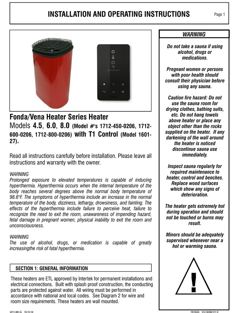
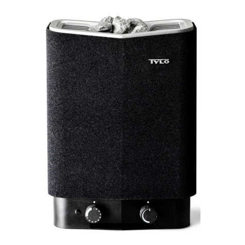
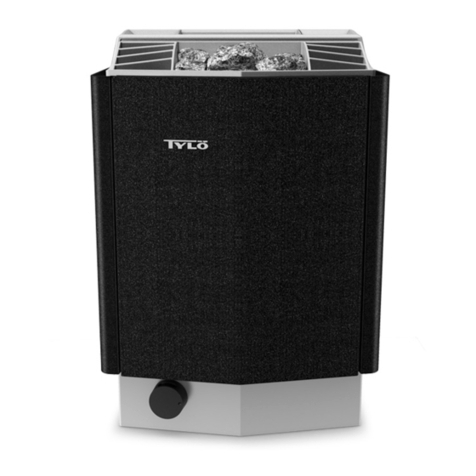
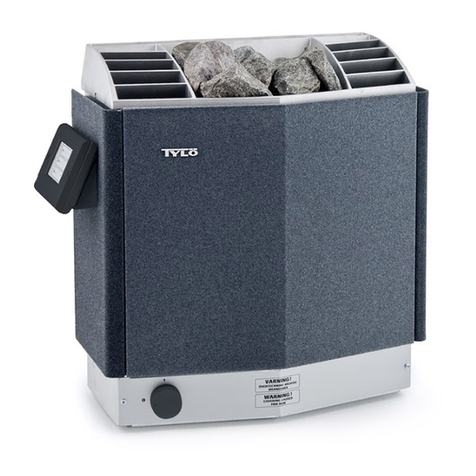
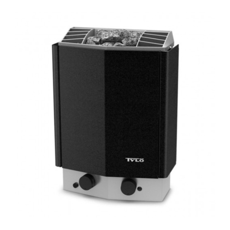
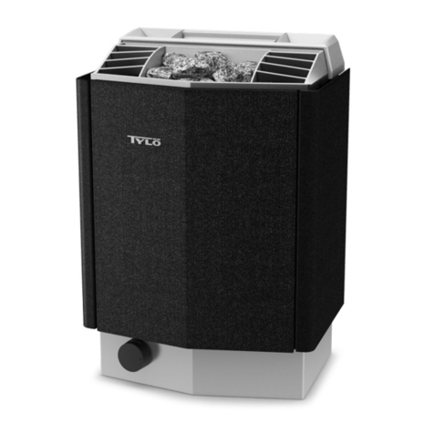
Tylo SENSE SPORT User manual

SENSE SPORT
Page
INSTALLATIONSANVISNING SVENSKA 2
INSTALLATION GUIDE ENGLISH 12
DEUTSCHINSTALLATIONSANLEITUNG DEUTSCH 22
NOTICE D'INSTALLATION FRANÇAIS 32
ИНСТРУКЦИИ ПО УСТАНОВКЕ РУССКИЙ 42
INSTRUKCJA INSTALACJI POLSKI 52
INSTALLATIEHANDLEIDING NEDERLANDS 62

1311
SVENSKA
INSTALLATIONSANVISNING
SENSE SPORT
29005175-SVE

X
Denna bruksanvisning bör sparas!
Vid eventuella problem, kontakta inköpsstället.
© Eftertryck, helt eller delvis, är förbjudet utan Tylös skriftliga
tillstånd. Rätt till ändringar i material, konstruktion och design
förbehålls.
INNEHÅLL
Före installation ............................................................. 1
Delar .......................................................................................1
Krav för installation ................................................................ 1
Verktyg för installation ............................................................1
Planering av installation .........................................................1
Installation ...................................................................... 3
Installation av bastuaggregat ................................................. 3
Anslutning/kopplingsschema ....................................... 6
Egenkontroll av installation .......................................... 7

1
FÖRE INSTALLATION
Delar
Kontrollera att följande delar finns med i emballaget:
3
2
1
6
5
4
7
Fig 1: Bastuaggregatets delar
1. Bastuaggregat
2. Örtskål/luftfuktare
3. Konsoler x 4 st
4. Varningsetikett på tio språk
5. Konsolskruvar x 4 st
6. Överkopplingsbleck x 3 st
7. Låsskruv B8x9,5 x 1 st
Kontakta återförsäljare om någon del saknas.
Krav för installation
För utförliga instruktioner angående basturumsbygge/ventilation
o. dyl. gå till: http://www.tylö.se/byggabastu och ladda ner doku-
mentet: "Hur du bygger bastu.pdf".
För säker användning av aggregatet, kontrollera att följande krav
tillgodoses:
• Basturummet ska uppfylla krav på takhöjd och dimensioner
enligt: "Hur du bygger bastu.pdf".
• Basturummet ska uppfylla krav på isolering och material en-
ligt: "Hur du bygger bastu.pdf".
• Kabel (EKK) eller elrör för anslutning av aggregatet dras på
utsidan av värmeisoleringen.
• Kabeldragningarna ska vara korrekt utförda (se Avsnittet An-
slutning/kopplingsschema, sidan 6).
• Säkringens storlek (A) och strömkabelns storlek (mm²) ska
passa aggregatet (se Avsnittet Anslutning/kopplingssche-
ma, sidan 6).
• Ventilation av bastu ska utföras enligt instruktioner i denna
manual (se Avsnittet Inluftsventilens placering, sidan 2,
Avsnittet Utluftsventilens placering, sidan 3).
• Placering av bastuaggregat ska ske enligt instruktionerna i
denna manual.
• Aggregatets effekt (kW) ska vara anpassat till bastuns volym
(m³) (se Tabell 1, sidan 1). Minimivolymen får inte under-
skridas och maximivolymen får inte överskridas.
NOTERA! En murad stenvägg utan värmeisole-
ring ökar föruppvärmningstiden. Varje kvadratmeter
av putsad tak- eller väggyta motsvarar ett tillägg på
1,2–2 m³ till bastuns volym.
Tabell 1: Effekt och bastuvolym
Effekt kW Bastuvolym min/max m³
6,6 4-8
8 6-12
!
FARA! Felaktig ventilation eller felaktig placering av
aggregat kan under vissa betingelser medföra torr-
destillation med risk för brand!
!
FARA! Otillräcklig isolering av basturummet kan
medföra risk för brand!
!
FARA! Användning av felaktiga material i basturum,
som t.ex. spånplatta, gips o.s.v. kan medföra risk för
brand!
!
FARA! Anslutning av aggregatet skall utföras av be-
hörig elektriker enligt gällande föreskrifter!
Verktyg för installation
Följande verktyg/material behövs för montering/anslutning:
• vattenpass,
• skiftnyckel,
• borrmaskin,
• skruvmejslar.
Planering av installation
Innan du påbörjar monteringen av bastuaggregatet bör du:
• Planera bastuaggregatets placering (se Avsnittet Aggrega-
tets placering - normalmontage, sidan 2).
• Placera inluftsventilen (se Avsnittet Inluftsventilens place-
ring, sidan 2).
• Placera utluftsventilen (se Avsnittet Utluftsventilens place-
ring, sidan 3).
• Planera elinstallationen se Avsnittet Anslutning/kopplings-
schema, sidan 6.

2
Aggregatets placering - normalmontage
!
FARA! Det är ej tillåtet att montera mer än ett bastu-
aggregat i samma basturum.
Placera bastuaggregatet:
• på samma vägg som dörren (endast i undantagsfall på sido-
väggen, men då mycket nära dörrväggen). Aggregatet kan
också placeras i nisch (se Fig 3, sidan 2).
• på säkert avstånd till golvet, sidoväggar och inredning (se Fig
2, sidan 2).
13
6
5
7
4
2
Fig 2: Placering av bastuaggregatet - normalmontage
1. Minsta avstånd till sidovägg: 110 mm
2. Minsta avstånd till tak: 1030 mm
3. Minsta avstånd till inredning: 100 mm
4. Minsta takhöjd: 1900 mm
5. Minsta avstånd: 20 mm
6. Minsta avstånd till inredning: 30 mm
7. Avstånd till golv: 100-270 mm, (med ben: 100 mm)
Aggregatets placering - nischmontage
Placera aggregatet på säkert avstånd till golv, sidovägg och in-
redning (se Fig 3, sidan 2).
4
7
6
8
2
1 1 5
3
Fig 3: Placering av bastuaggregat - nischmontage
1. Minsta avstånd till sidovägg: 200 mm
2. Max 1000 mm
3. Minsta avstånd till tak: 1030 mm
4. Minsta avstånd till inredning: 100 mm
5. Minsta takhöjd: 1900 mm
6. Minsta avstånd: 20 mm
7. Minsta avstånd till inredning: 30 mm
8. Avstånd till golv: 100-270 mm, (med ben: 100 mm)
Inluftsventilens placering
Placera inluftsventilen rakt genom väggen mitt under aggregatet.
Ventilstorlek för en familjebastu ca. 125 cm².
Dörrens luftcirkulation skall samarbeta med varmluften från ag-
gregatet.

3
1 2
3 4
Fig 4: In- och utluftsventilens placering
1. Inluftsventilens placering.
2. Utluftsventilens placering genom bastuvägg.
3. Utluftsventilens placering genom tomrum.
4. Utluftsventilens placering via trumma.
Utluftsventilens placering
!
FARA! Utluftsventil skall ej mynna ut i det fria. Detta
kan påverka aggregatets temperaturskydd då venti-
lationsriktningen kan bli omvänd.
!
FARA! Eventuellt tomrum ovanför bastutaket får ej
vara helt inneslutet, utan måste ha minst ett ventil-
hål på samma vägg som bastudörren!
Placera utluftsventilen:
• med maximalt avstånd till inluftsventilen, t.ex. i diagonal (se
Fig 4, sidan 3).
• högt på väggen eller i taket (se Fig 4, sidan 3).
• så att den utmynnar till det utrymme som dörr och inluftsventil
mynnar till.
Utluftsventilen ska ha samma area som inluftsventilen.
Tillse att utluftsventilen är öppen.
Mekaniskt ventilation rekommenderas ej p.g.a. risk för felaktig
luftväxling som kan påverka aggregatets temperaturskydd nega-
tivt.
INSTALLATION
Installation av bastuaggregat
Förberedelserna för installation görs enklast när aggregatet ligger
ner.
För att installera aggregatet:
1. Lägg aggregatet med fronten upp.
2. Lossa skruvarna och öppna luckan (se Fig 5, sidan 3).
Fig 5: Öppna/stänga luckan
3.
!
VARNING! Se alltid till att aggregatet ansluts
med rätt huvudspänning/fasspänning!
Aggregatet ansluts med vanlig standardledning (Fk eller
EKK), godkänd för fast installation.
Eventuell enkelledare (Fk) skyddas i elrör (VP) fram till aggre-
gatet.

4
Anslut elkabeln (1) i plint (2) (se Fig 6, sidan 4) enligt
kopplingsschema (se Avsnittet Anslutning/kopplingssche-
ma, sidan 6).
1
2
Fig 6: Kretskortet
1. Elkabel
2. Plint för inkoppling av elkabel
4. Stäng luckan och skruva i skruvarna (se Fig 5, sidan 3).
5.
!
OBS! Om alla baksidans skruvar lossas samti-
digt kan baksidans plåt lossna. Montera därför
de fyra konsolerna en i taget på aggregatet.
Lossa de två första skruvarna på aggretatets baksida och
skruva fast en av de fyra konsolerna. Upprepa proceduren tills
alla konsolerna sitter på plats se Fig 7, sidan 4.
Fig 7: Montera konsolerna på aggregatet
6. Placera konsolskruvarna enligt måttsättning se Fig 8, sidan
4.
2
4
3
1
Fig 8: Måttsättning
1. 262 mm
2. 270 mm
3. 532 mm
4. 206 mm
7. Montera örtskål/luftfuktare (se Fig 9, sidan 4).
Fig 9: Montering av doftbehållare/luftfuktare
8. Häng upp aggregatet på skruvarna se Fig 10, sidan 4.
Fig 10: Häng upp aggregatet

5
9. Lås aggregatet på plats med låsskruven se Fig 11, sidan
5.
Fig 11: Konsolens låsskruv
Ovanliga spänningar/fas-tal
Vid inkoppling till spänningar eller fas-tal, som inte anges i kopp-
lingsschema Fig 12, sidan 6, kontakta Tylö kundservice.

6
ANSLUTNING/KOPPLINGSSCHEMA
400-415 V 3N~/3~ 230-240 V 3~ 230-240 V~
Effekt kW Strömstyrka
amp
Ledningsarea mm² Strömstyrka
amp
Ledningsarea mm² Strömstyrka
amp
Ledningsarea
mm²
6,6 10 1,5 17 4 29 10
8 12 2,5 20 4 35 10
1
2
1
A 3 x TAB
B
4 x TAB
C 5 x TAB
D
4 x TAB
Fig 12: Kopplingsschema
1. Aggregat
2. Plint för inkoppling av elkabel

7
EGENKONTROLL AV INSTALLATION
För att kontrollera installationen:
1. Slå på huvudspänning till aggregat från elcentral.
2. Starta aggregatet (se Bruksanvisning).
3. Kontrollera att alla de tre rörelementen går igång (blir röda).


1311
ENGLISH
INSTALLATION GUIDE
SENSE SPORT
29005175 -ENG

X
Keep this user guide!
In the event of any problems, please contact the retailer
where you purchased the equipment.
© This publication may not be reproduced, in part or in whole,
without the written permission of Tylö. Tylö reserves the right to
make changes in materials, construction and design.
TABLE OF CONTENTS
Before installation ..........................................................1
Parts .......................................................................................1
Installation requirements ........................................................ 1
Installation tools ..................................................................... 1
Planning installation ............................................................... 1
Installation ...................................................................... 3
Sauna heater installation ....................................................... 3
Connection/wiring diagram ........................................... 6
Checking installation ..................................................... 7

1
BEFORE INSTALLATION
Parts
Check that the following parts are included in the packaging:
3
2
1
6
5
4
7
Figure 1: Sauna heater parts
1. Sauna heater
2. Herb bowl/air humidifier
3. Bracketsx 4
4. Warning sticker in ten languages
5. Bracket screws x 4
6. Connectors x 3
7. Lock screw B8x9.5 x 1
Contact your dealer if anything is missing.
Installation requirements
For detailed instructions concerning sauna construction/ventila-
tion etc., go to: http://www.tylö.se/byggabastu and download this
document: "Building a sauna.pdf".
To ensure safe use of the heater, check that the following criteria
are met:
• The sauna cabin should meet the requirements for ceiling
height and dimensions according to: "Building a sauna.pdf".
• The sauna cabin should meet the requirements for insulation
and materials according to: "Building a sauna.pdf".
• Cable (EKK) or electrical ducting for connecting the heater
must be run on the outside of the heat insulation.
• Cable installation must be correctly performed (see The sec-
tion called Connection/wiring diagram, Page 6).
• Fuse size (A) and power cable size (mm²) must be suitable
for the heater (see The section called Connection/wiring dia-
gram, Page 6).
• The sauna ventilation must comply with the instructions in this
manual (see The section called Positioning the inlet vent,
Page 2, The section called Positioning the outlet vent,
Page 3).
• The position of the sauna heater must comply with the instruc-
tions in this manual.
• The heater output (kW) must be suitable for the sauna volume
(m³) (see Table 1, Page 1). The minimum and maximum
volumes must not be exceeded.
NOTE! A brick wall without heat insulation increases
the warm-up time. Each square metre of plastered
ceiling or wall surface equals an additional 1.2–2 m³
of sauna volume.
Table 1: Output and sauna volume
Output kW Sauna volume min./max. m³
6,6 4-8
8 6-12
!
DANGER! Incorrect ventilation or heater positioning
can lead to the wooden panels drying out, posing a
fire risk in certain circumstances.
!
DANGER! Insufficient insulation of the sauna cabin
can pose a fire risk.
!
DANGER! Use of the wrong materials in the cabin,
such as chipboard, plasterboard etc., can pose a fire
risk.
!
DANGER! The heater must be connected by a qual-
ified electrician according to the applicable regula-
tions.
Installation tools
The following tools and materials are needed for installation and
connection:
• spirit level,
• adjustable spanner,
• electric drill,
• screwdriver.
Planning installation
Before starting to install your sauna heater:
• Plan where to position the sauna heater (see The section
called Positioning the heater - normal installation, Page
2).
• Position the inlet vent (see The section called Positioning the
inlet vent, Page 2).
• Position the outlet vent (see The section called Positioning
the outlet vent, Page 3).
• Plan the electrical installation see The section called Connec-
tion/wiring diagram, Page 6.

2
Positioning the heater - normal installation
!
DANGER! More than one heater can be installed in
the same sauna cabin.
Position the sauna heater:
• on the same wall as the door (or the side wall if very close to
the door wall). The heater can also be positioned in a recess
(see Figure 3, Page 2).
• at a safe distance from the floor, side walls and interior fittings
(see Figure 2, Page 2).
13
6
5
7
4
2
Figure 2: Positioning the heater - normal installation
1. Minimum distance from side wall: 110 mm
2. Minimum distance from ceiling: 1030 mm
3. Minimum distance from interior fittings: 100 mm
4. Minimum ceiling height: 1900 mm
5. Minimum distance: 20 mm
6. Minimum distance from interior fittings: 30 mm
7. Distance from floor: 100-270 mm (with legs: 100 mm)
Positioning the heater - recess installation
Position the heater at a safe distance from the floor, side walls
and interior fittings (see Figure 3, Page 2).
4
7
6
8
2
1 1 5
3
Figure 3: Positioning the heater - recess installation
1. Minimum distance from side wall: 200 mm
2. Max. 1000 mm
3. Minimum distance from ceiling: 1030 mm
4. Minimum distance from interior fittings: 100 mm
5. Minimum ceiling height: 1900 mm
6. Minimum distance: 20 mm
7. Minimum distance from interior fittings: 30 mm
8. Distance from floor: 100-270 mm (with legs: 100 mm)
Positioning the inlet vent
Install the inlet vent straight through the wall under the centreline
of the heater. Vent size for a family sauna approx. 125 cm².
The air circulation from the door must concord with the hot air cir-
culation from the heater.

3
1 2
3 4
Figure 4: Positioning the inlet and outlet vents
1. Inlet vent position.
2. Outlet vent position through the sauna wall.
3. Outlet vent position through the cavity.
4. Outlet vent position via duct.
Positioning the outlet vent
!
DANGER! The outlet vent must not lead outdoors.
This could cause the ventilation direction to be re-
versed, which may negatively affect the heater tem-
perature cut-out.
!
DANGER! Any gap above the sauna ceiling should
not be sealed without leaving at least one vent hole
on the same wall as the sauna door.
Position the outlet vent
• at the maximum possible distance from the inlet vent, e.g. di-
agonally (see Figure 4, Page 3).
• high on the wall or in the ceiling (see Figure 4, Page 3).
• so that it vents into the space the door and inlet vent open in-
to.
The outlet vent must have the same area as the inlet vent.
Ensure that the outlet vent is open.
Mechanical ventilation is not recommended due to the risk of poor
air exchange, which can negatively affect the heater temperature
cut-out.
INSTALLATION
Sauna heater installation
It is easiest to prepare for installation with the heater lying down.
To install the heater:
1. Lay the heater down front upwards.
2. Slacken the screws and open the cover (see Figure 5, Page
3).
Figure 5: Opening/closing the cover
3.
!
WARNING! Always check that the heater is con-
nected to the correct main/phase voltage.
Connect the heater using standard wiring (Fk or EKK) ap-
proved for fixed installation.
Any single wires (Fk) must be protected in electrical conduits
(VP) to the heater.

4
Connect the electrical cable (1) to terminal (2) (see Figure
6, Page 4) according to wiring diagram (see The section
called Connection/wiring diagram, Page 6).
1
2
Figure 6: Circuit board
1. Electrical cable
2. Terminal for connection of electrical cable
4. Close the cover and tighten the screws (see Figure 5, Page
3).
5.
!
CAUTION! If all the screws on the back are un-
screwed simultaneously, the back plate may
come loose. For this reason, attach the four
brackets to the heater one at a time.
Unscrew the first two screws on the back of the heater and
screw one of the four brackets into place. Repeat the pro-
cedure until all of the brackets are fitted see Figure 7, Page
4.
Figure 7: Attaching the brackets to the heater
6. Position the bracket screws according to the specified dimen-
sioning see Figure 8, Page 4.
2
4
3
1
Figure 8: Dimensioning
1. 262 mm
2. 270 mm
3. 532 mm
4. 206 mm
7. Attach the herb bowl/air humidifier (see Figure 9, Page
4).
Figure 9: Fitting the fragrance holder/air humidifier
8. Hang the heater on the screws se Figure 10, Page 4.
Figure 10: Hang the heater up.

5
9. Lock the heater into place with the lock screw see Figure 11,
Page 5.
Figure 11: Lock screw for bracket
Unusual voltages/numbers of phases
Before connecting to voltages or numbers of phases not listed in
the wiring diagram Figure 12, Page 6, contact Tylö Customer
Service.

6
CONNECTION/WIRING DIAGRAM
400-415 V 3N~/3~ 230-240 V 3~ 230-240 V~
Output kW Amperage Wiring area mm² Amperage Wiring area mm² Amperage Wiring area mm²
6,6 10 1,5 17 4 29 10
8 12 2,5 20 4 35 10
1
2
1
A 3 x TAB
B
4 x TAB
C 5 x TAB
D
4 x TAB
Figure 12: Wiring diagram
1. Heater
2. Terminal for connection of electrical cable

7
CHECKING INSTALLATION
To check the installation:
1. Switch on the mains supply to the heater from the distribution
board.
2. Start the heater (see User Guide).
3. Check that all three tubular elements start to heat up (go red).
Other manuals for SENSE SPORT
6
Table of contents
Languages:
Other Tylo Heater manuals

Tylo
Tylo 1712-450-0206 User manual

Tylo
Tylo SENSE PLUS/MPE User manual

Tylo
Tylo Sense Pure User manual

Tylo
Tylo Expression Combi User manual

Tylo
Tylo Combi User manual

Tylo
Tylo MPE User manual

Tylo
Tylo SU 2/4 User manual

Tylo
Tylo SENSE SPORT User manual

Tylo
Tylo SENSE SPORT User manual

Tylo
Tylo SENSE SPORT COMBI 4 User manual

Tylo
Tylo CROWN ELITE User manual

Tylo
Tylo Combi Compact h1 User manual

Tylo
Tylo H2 User manual

Tylo
Tylo SK 210 User manual

Tylo
Tylo AIR User manual

Tylo
Tylo SENSE SPORT 2/4 User manual

Tylo
Tylo SENSE COMBI User manual

Tylo
Tylo Sense Combi-U7 User manual

Tylo
Tylo SENSE SPORT COMBI 4 User manual

Tylo
Tylo SENSE ELITE User manual