Tylo Sense Combi USA Pure Operation manual

2016-10-18
2900 5260
SENSE COMBI USA Pure/Elite
ENGLISH
INSTALLATION / USER GUIDE
FRANÇAIS
NOTICE D’INSTALLATION ET D’UTILISATION
Compliments of www.saunasandstuff.com

2
INSTALLATION GUIDE................................................ 3
BEFORE INSTALLATION .................................................... 3
Parts ....................................................................... 3
Installation requirements ........................................ 3
Installation tools ...................................................... 3
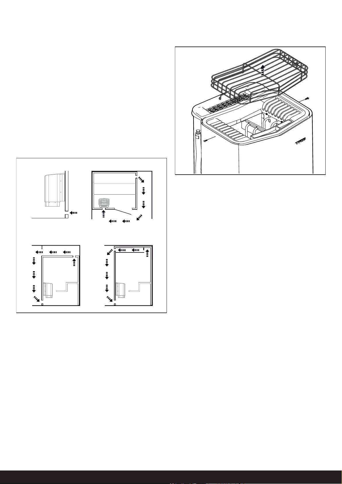
Installation planning ............................................... 3
INSTALLATION .................................................................... 6
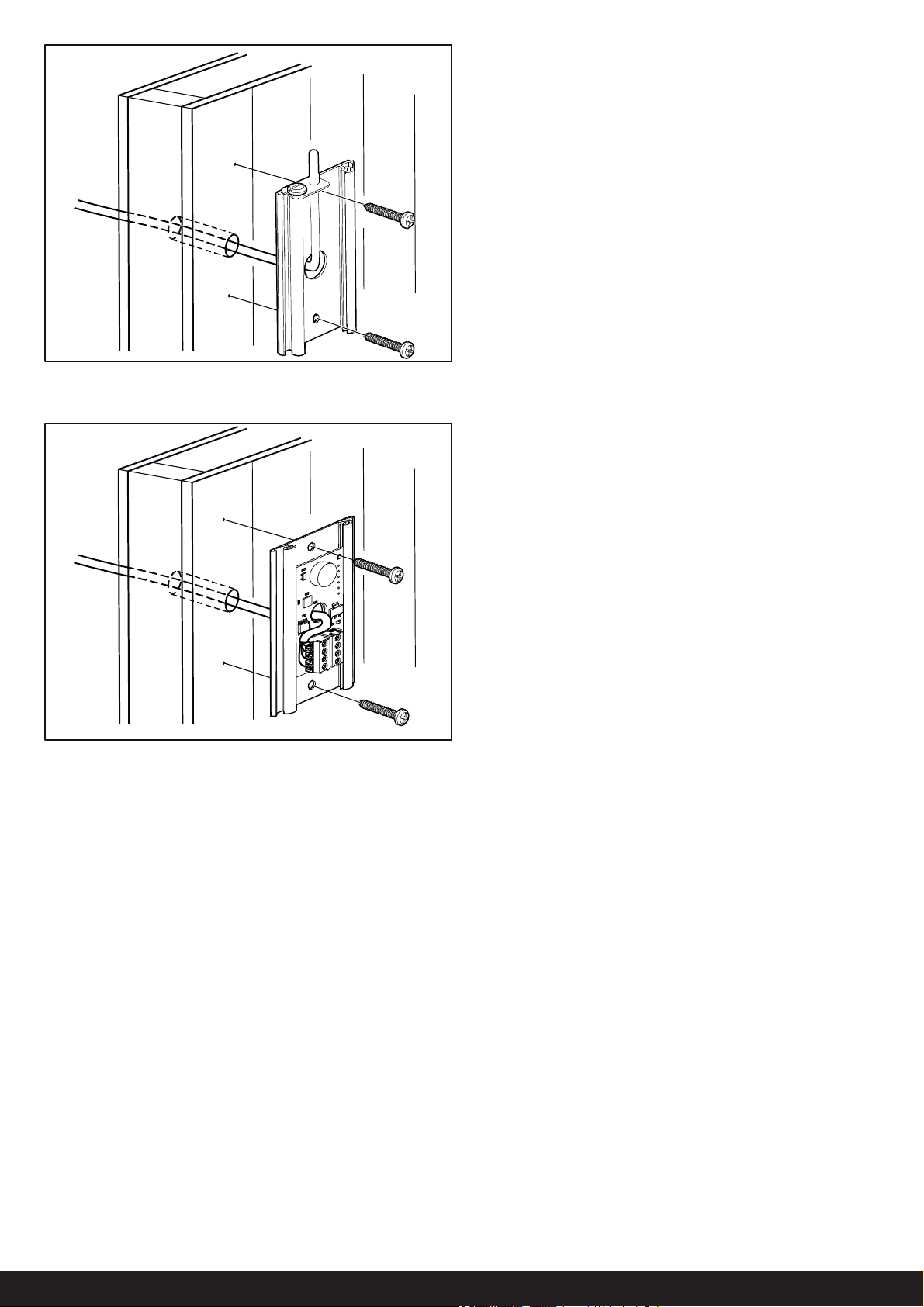
Sauna heater installation ........................ ................ 6
External ON/OFF switch (option) ........................... 8
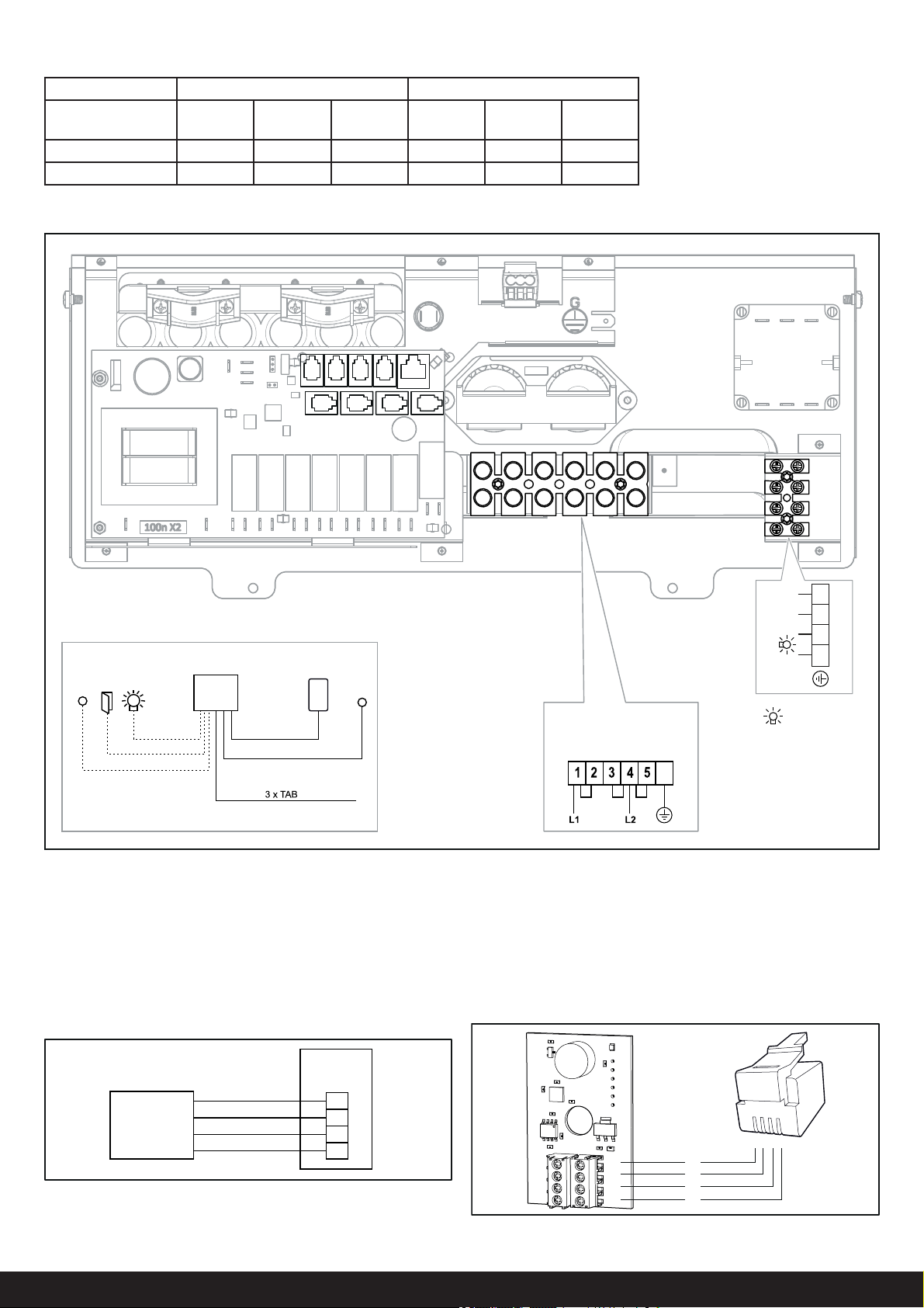
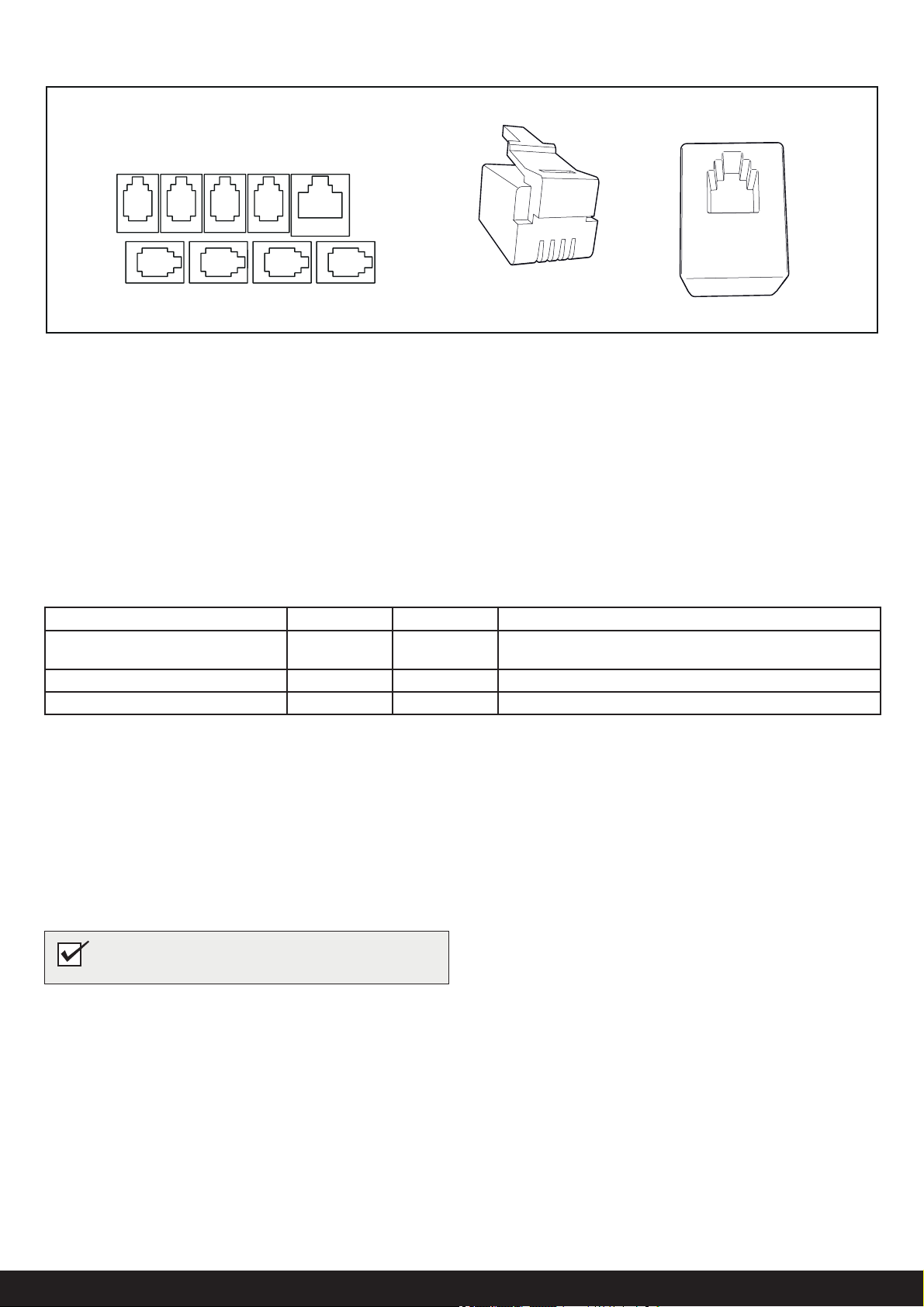
CONNECTION/WIRING ....................................................... 9
Description of cabling/modular contacts ................. 10
SELF-INSPECTION OF THE INSTALLATION................... 10
DIMENSIONS.......................................................................... 11
USER GUIDE............................................................... 12
GENERAL INFORMATION .................................................. 12
PRIOR TO USE ..................................................................... 12
The fi rst time you use the heater ............................ 1 2
Prior to each use .................................................... 12
USE ........................................................................................ 13
The control panel in general.................................... 13
Water reservoir........................................................ 13
Other functions........................................................ 13
EXTERNAL ON/OFF SWITCH (OPTION)........................... 14
AFTER USE .......................................................................... 14
Empty the reservoir................................................. 14
Switch off main power switch.................................. 14
MAINTENANCE .................................................................... 14
Descaling the water reservoir.................................. 15
Cleaning the fragrance holder/air humidifi er
and
herb bowl................................................................. 15
Check the stone compartment ............................... 15
TROUBLESHOOTING ......................................................... 15
Troubleshooting the control panel .......................... 15
Troubleshooting the sauna heater.......................... 16
SPARE PARTS LIST ............................................................ 17
ROHS (RESTRICTION OF HAZARDOUS SUBSTANCES)
...... 17
HEATER WIRING DIAGRAM
................................................... 18
WARNING!
• Electric Shock Hazard - High voltage exists within this
equipment. There are no user serviceable parts in this
equipment. All installation and service to this equipment
should be performed by qualifi ed licensed personnel in
accordance with local and national codes.
• Do not construct sauna room so as to restrict air fl ow
through the bottom of the heater.
• Packing the rocks too tightly may cause the heater high
limit switch to trip.
• Maintain minimum clearance from heater to wooden sur-
faces (benches, side walls, heater fence etc.). Mounting
brackets supplied. Provides proper clearance from wall
behind heater.
• Use only copper wire of the size and type indicated in the
Heater Specifi cation Chart and the temperature rating
indicated on the heater junction box.
• A guardrail or fence is required around the heater to pre-
vent burns from accidental contact.
• All heaters and controls must be grounded per NEC to
prevent electrical shock in case of unit failure.
• Electrical outlets or receptacle must not be installed in a
sauna room.
• Do not locate benches over heater.
• For household only.
Keep this user guide!
In the event of any problems, please contact the re-
tailer where you purchased the equipment.
© This publication may not be reproduced, in part or in whole, without
the written permission of Tylö. Tylö reserves the right to make changes in
materials, construction and design.
* Hyperthermia occurs when the internal temperature of
the body reaches a level several degrees above the normal
temperature of 98.6° F. The symptoms of hypothermia include
an increase in the internal temperature of the body, dizziness,
lethargy, drowsiness and fainting. The effect of hyperthermia
include:
a) Failure to perceive heat;
b) Failure to recognize the need of exit the room;
c) Unawareness of impending hazard;
d) Fatal damage of pregnant women;
e) Physical inability to exit the room; and
f) Unconsciousness
• Do not take a sauna if using alcohol, drugs or medica-
tions.
• Pregnant women or persons with poor health should con-
sult their physician before using any sauna.
• Caution fi re hazard: Do not use the sauna room for drying
clothes, bathing suits, etc. Do not hang towels above
heater or place any object other than the rocks supplied
on the heater. If any darkening of the wall around the
heater is noticed discontinue sauna use immediately.
• Inspect sauna regularly for required maintenance to heat-
er, control and benches. Replace wood surfaces which
show any signs of deterioration.
• The heater gets extremely hot during operation and
should not be touched or burns may result.
• Minors should be adequately supervised whenever near a
hot or warming sauna.
• Fire sprinkler systems used inside any sauna room should
be properly rated for sauna room temperatures.
• Do not pour chlorinated pool or spa water on heater.
Excessive water use on heater may cause damage and
void warranty.
• This appliance is not intended for use by persons (includ-
ing children) with reduced physical, sensory or mental
capabilities, or lack of experience and knowledge, unless
they have been given supervision or instruction concern-
ing use of the appliance by a person responsible for their
safety. Children should be supervised to ensure that they
do not play with the appliance.
Compliments of www.saunasandstuff.com

3
INSTALLATION GUIDE
BEFORE INSTALLATION
Parts
Check that the following parts are included in the packaging:
Figure 1: Sauna heater/control panel parts
1. Sauna heater
2. Herb bowl/air humidifi er
3. Herb bowl
4. Brackets
5. Warning and Caution plates for the room in multiple languages
6. Screws B 4 x 6.5 x 6 for Warning and Caution plates
7. Connectors x 3
8. Spacers x 4
9. Screws x 4
10. Bracket screws x 2
11. NTC-sensor (Combi Pure)
12. Screw B4x6,5 (x 1 Combi Pure) (x 2 Combi Elite)
13. Sensor cover (Combi Pure)
14. Clips TC (3-5) x 10 pieces
15. Plastic plugs 25x5 x 2 pcs
16. Screws B6x25 x 2 pcs
17. Humidity- and temperature sensor with cover (Combi Elite)
18. Cable between heater and humidity- and temperature sensor,
RJ10 4P4C, cable length 4 m x 1 pce (Combi Elite)
19. Control panel (Elite Wifi or Pure)
20. Cable between heater and control panel, RJ10 4P4C, cable
length 5 m x 1 pce
21. Cable tie
22. Clips C 3x5 x 10 pieces
23. Modular plug 4, 4/4RJ10 x 2
24. Plastic plugs 25x5 x 3 pcs
25. Screws B6x25 x 3 pcs
26. Rock guard
27. Protection hose Ø14x150 mm x 3 pcs, for RJ10 cables (sen-
sor, control panel, door switch)
Installation tools
The following tools and materials are needed for installation and
connection:
• level
• tape measure
• electric drill
• screw drivers
Installation planning
Before starting to install your sauna heater:
• Plan the sauna heater positioning (see the Heater positioning
- normal installation section, page 4).
• Plan the control panel positioning (see the attached instruc-
tions for the control panel for allowable positioning).
• Plan the sensor positioning (see Figure 3, page 4).
• Position the air intake vent (see the Air intake vent positioning
section, page 5).
• Position the air exhaust vent (see the Air exhaust vent posi-
tioning section, page 5).
• Plan the electrical installation (see the Connection/wiring
diagram section, page 9).
32
1
4
10
9
6
8
7
22
20
23 24 25
26
27
21
5
11
14 15 16
12
13
17
Pure
19
18
Elite
WiFi
Table 1: Voltage and sauna volume
Model Voltage Sauna volume
min. cu.ft.
Sauna volume
max. cu.ft.
Sense Combi-U 7
SCU7
208 V
240 V
175
175
265
320
Sense Combi-U 8
SCU8
208 V
240 V
250
250
360
440
Contact your dealer if anything is missing.
Control panel Pure is supplied with Sense Combi Pure.
Control panel Elite WiFi is supplied with Sense Combi Elite.
See separate guides.
Installation requirements
To ensure safe use of the heater, check that the following criteria
are met:
• Electrical wiring should be installed in accordance with NEC
and all state and local codes.
• Fuse size (A) and power cable size (AWG) must be suitable
for the heater (see The section called Connection/wiring
diagram, Page 9.
• The sauna ventilation must comply with the instructions in
this manual (see The section called Positioning the inlet vent,
Page 5, The section called Positioning the outlet vent, Page
5).
• The position of the sauna heater, control panel, and sensors
must comply with the instructions in this manual.
• The heater output (kW) must be suitable for the sauna
volume (cu.ft.) (See Table 1, Page 3). The minimum and
maximum volumes must not be exceeded.
• NOTE: A GFCI device is not required by ETL. A GFCI may
be installed if required by local codes. However, GFCI devic-
es will tend to nuisance trip during use of the product.
Compliments of www.saunasandstuff.com

4
1
3
2
4
Figure 2: Schematic diagram of installation
1. Sauna heater
2. Control panel
3. Sensor
4. External on/off switch (option, door contact needed for func-
tion)
Positioning the heater - normal installation
Position the sauna heater:
• on the same wall as the door (or the side wall if very close to
the door wall).
• Position the heater at a safe distance from the fl oor, side
walls and interior fi ttings (see Figure 3).
Position the sensor according the picture (see Figure 3).
17
10
9
8
11
6
4
3
23
5
Figure 3: Positioning the heater - normal installation
1. Minimum distance from side wall: 4 in
2. Sensor position alt 1: 3 in from heater
3. Sensor
4. Sensor position alt 2: 3 in from heater front
5. Sensor position: 1 in from ceiling
6. Minimum distance from ceiling: 44 in
7. Minimum distance from interior fi ttings: 4 in
8. Minimum ceiling height: 75 in
9. Minimum distance: 1 in
10. Minimum distance from interior fi ttings: 2 in
11. Distance from fl oor: 7 in
Positioning the control panel
The control panel can be installed inside or outside of the sauna
room.
The control panel must be correctly positioned with regard to
safety distances below when installed inside the sauna room
Figure 4: Safety distance, control panel
1. Heater
2. Control panel
3. Max. 36 in
4. Min. 12 in
Figure 5: Warning/Caution plate
1
2
4
3
DANGER! No more than one heater may be instal-
led in the same sauna cabin.
Compliments of www.saunasandstuff.com

5
Sauna room ventilation
In a sauna, the air should be changed about 6 times an hour. See
Figure 6.
It is recommended that ventilation openings meet the require-
ments of UL Specifi cation 875. The minimum opening should be
determined using one of the following formulas:
For R< 31, V ≥ 9 .3
For R ≥ 31, V ≥ 0.3*R
where R = the fl oor area of the room in square feet and
V = the minimum vent size in square inches
ExampleVenting Calculation:
Room is 54 sq.ft.(9 ft. by 6 ft.) 54 is larger than 31.
Multiple 54 x 0.3 = 16.2 sq. in.
Vent size opening should be 4 in x 4 in.
Positioning the inlet vent
Install the inlet vent straight through the wall under the centerline
of the heater.
Figure 6: Positioning the air intake and exhaust vents
1. Inlet vent position.
2. Outlet vent position through the sauna wall.
3. Outlet vent position through the cavity.
4. Outlet vent position via duct.
Positioning the outlet vent
Position the outlet vent
• at the maximum possible distance from the air intake vent,
e.g. diagonally (see Figure 6).
• high on the wall or in the ceiling (see Figure 6).
• so that it vents into the space that the door and air intake
vent open into.
The outlet vent must have the same area as the inlet vent.
Ensure that the outlet vent is open.
Mechanical ventilation is not recommended due to the risk of poor
air exchange, which can negatively aff ect the heater temperature
cut-out.
Removing the Rock Guard
Unscrew the two screws on the side of the heater and lift the
rock guard upwards, see Figure 7. (This is necessary when fi lling
the stone compartment or cleaning the fragrance holder and air
humidifi er).
1 2
34
Figure 7: Removing the Rock Guard
Room construction
For safety and reliability, the following rules must be addressed.
• The enclosed WARNING: Reduce the risk of overheating
… warning plate must be mounted on or alongside the door
outside the sauna room at about eye level. Use the supplied
screws.
• The enclosed CAUTION: Reduce the risk of fi re … caution
plate must be mounted on the interior wall above the heater.
Use the supplied screws.
• No permanent locking or latch system is to be used on the
sauna door.
• Acceptable door fi ttings are: magnetic catches, friction catch-
es, spring or gravity loaded closures. The door must always
open outwards.
• No shower may be installed in a sauna room.
• No electrical receptacle shall be installed inside the sauna
room.
• The heater should not be operated without its container prop-
erly fi lled with rocks and the rock guard in place.
• If an intercom speaker is installed, it should be away from the
heater and as close to the fl oor as possible.
• If a room light is installed, it should be a surface mounted
bracket type. Wall mounted lights should be about 70” above
the fl oor. Ceiling mounted lights should be of an approved
type with a junction box that is remote to the fi xture itself.
Use only a fi xture that uses A.F. or fi xture type internal wiring.
A 60 watt bulb should provide suffi cient lighting.
• Fire sprinkler systems installed inside any sauna room should
be properly rated for sauna room temperatures.
• Always mount the heater according to these installation
instructions.
Compliments of www.saunasandstuff.com

6
Figure 10: Opening/closing the cover
Figure 8: Typical wall construction
Connect the heater using standard wiring (Fk or EKK) approved
for fi xed installation.
Any single wires (Fk) must be protected in electrical conduits (VP)
to the heater.
4. Connect the main supply electrical cable (1) to the terminal
(2) (see Figure 11) according to the wiring diagram (see the
Connection/wiring diagram section, page 9).
It is easiest to prepare for installation with the heater lying down.
To install the heater:
2. Remove the cover to the water reservoir and lay the heater
down with the front facing upwards (see Figure 10).
3. Undo the screws and open the cover (see Figure 10).
WARNING! Always check that the heater is con-
nected to the correct main/phase voltage!
5. Run the cables for the control panel and the temperature
sensor through the cable grommets (3). Connect the control
panel cable (4) to one of the four RS485 contacts (positions
6-9) (see Figure 11) according to the wiring diagram (see the
Connection/wiring diagram section, page 9 fi g.19).
6. Connect the humidity- and temperature sensors cable (6) to
one of the four RS485 contacts (positions 6-9) (5) according
to the wiring diagram (see the Connection/wiring diagram
section, page 9 fi g. 19).
2
8
4
5
7
6
9
110
3
11
Figure 11: Circuit board
1. Electrical cable
2. Terminal for connection of elec-
trical cable
3. Cable grommet (x6)
4. Control panel cable
5. Modular contacts for connection
of control panel, sensor etc.
6. Sensor cable
7. Light cable (if connected)
8. Terminal for connection of
light (if connected)
9. Strain relief connector for
cables to modular contacts
(x2)
10. Strain relief connector for
electrical cable
11. Protection hose for RJ10
cables
INSTALLATION
Sauna heater installation
1. Attach the bracket and spacers to the wall following the speci-
fi ed dimensioning (see Figure 9). -
Figure 9: Bracket with screws and spacers
1. 26.3 in
2. 11.0 in
3. 7.3 in
4. 9.0 in (minimum distance)
1
2
3
3
4
Typical wall construction
Compliments of www.saunasandstuff.com

7
7. Connect the light cable (if relevant) (7), see Figure 11, to the
terminal (8) according to the wiring diagram Figure 19.
8. Close the cover and tighten the screws (see Figure 10).
9. Hang the heater on the bracket (see Figure 12).
Figure 12: Hang the heater up.
10. Fit the spacers between heater and wall (to prevent the heat-
er from being lifted off ) (see Figure 13).
Fig 13: Fit spacers
11. Fit the cover for the water reservoir, herb grille and fragrance
holder/air humidifi er (see Figure 14).
Fig 14: Fitting the cover for the water reservoir, herb grille and
fragrance holder/air humidifier
12. Install the sensor on the wall see Fig 15 and 16. The therm-
istor wire may also be passed through the wall see Fig 17
and 18. Seal any holes in the wall behind the sensor. The
thermistor wire may be extended outside the sauna using low
voltage wire (2-lead).
Fig 16: Installing the humidity- and temperature sensor - Combi
Elite. The cable inside the sauna must be heat resistant.
Fig 15: Installing the sensor - Combi Pure.
Combi Elite
Combi Pure
Compliments of www.saunasandstuff.com

8
Unusual voltages/numbers of phases
Contact Tylö Customer Service before connecting to voltages or
numbers of phases that are not listed in the wiring diagram Figure
19.
External ON/OFF switch (option)
The external ON/OFF switch can be positioned anywhere outside
the sauna, not to exceed 75 feet from the heater, to avoid voltage
loss in the cable. Voltage loss aff ects the LED indicator for heater
status (if built-in and connected to the switch).
For further information, see instructions supplied with the control
panel.
Fig 18: Wiring through the wall - Combi Elite.
Fig 17: Wiring through the wall - Combi Pure.
Compliments of www.saunasandstuff.com

9
CONNECTION/WIRING DIAGRAM
TAB 208 V 1 Phase 240 V 1 Phase
Model Amperage
Amps
Output
kW
Wire Size
AWG
Amperage
Amps
Output
kW
Wire Size
AWG
Sense Combi-U 7 26 5,3 10 30 7,0 8
Sense Combi-U 8 30 6,3 8 35 8,3 8
Figure 19: Wiring diagram
Note: Heating elments do not change for voltage changes. The heater output will changed based on the voltage applied to heater.
1. NTC Sensor - Combi Pure.
2. Ext switch (External switch Optional)
3. N/A
4. N/A
5. N/A
6. Sensor (humidity- and temperature) - Combi Elite.
7. N/A
8. N/A
9. Controls panels (Pure or Elite).
10. Heater
11. Terminal for connection of electrical cable
12. Control panel (connect to positions 6-9)
13. Sensor - Combi Pure (connect to NTC position 1)
13. Humidity- and temperature sensor - Combi Elite
(connect to positions 6-9)
14. Light/terminal for connection of light
15. Door contact (option)
16. External switch (option)
10
141516 12 13
11
14
RJ10 4P4C
3 x 14 AWG
RJ10 4P4C RJ10 4P4C
RJ10 4P4C
max 75 feet - Combi Elite
max 300 feet - Combi Pure
*
**
*
**
BB4140
12
6789
34 5
120 V~
14 AWG
Max. 6 Amp.
5,3-8,3 kW
208/240 V~
G
Fig 20a: Connecting the humidity- and temperature sensor -
Combi Elite
1. Modular plug (RJ10, see Fig 19)
2. Humidity- and temperature sensor
A
B
11
12
1:A
2:B
Pin 3:12V
4:GND
12
Fig 20b: Connecting the humidity- and temperature sensor -
Combi Elite
R=Red, G=Green, W=White, B=Black
A
B
11
12
1234
R
G
W
B
Compliments of www.saunasandstuff.com

10
SELF-INSPECTION OF THE INSTALLATION
To check the installation:
1. Turn power on at the Circuit Breaker Box.
2. Check that the control panel lights up.
3. Start the heater (see User Guide).
4. Check that all three tubular elements start to heat up (go
red).
Please keep these instructions!.
In the event of problems, please contact the retailer where you purchased
the equipment.
© This publication many not be reproduced, in part or in whole, without
the written permission of Tylö. Tylö reserves the right to make changes to
materials, construction and design.
1234Pin:
Pos 1.
NTC
Pin 1:
Pin 2: NTC
Pin 3: NTC
Pin 4:
Pos 2.
Ext sw
Pin 1:
Pin 2: LED
Pin 3: SW
Pin 4: 12 V
Pos 6-9.
4x RS485
Pin 1: A
Pin 2: B
Pin 3: 12 V
Pin 4: GND
Pos 3.
Door sw
Pin 1:
Pin 2: LED
Pin 3: SW
Pin 4: 12 V
Pos 4.
Bim/NTC
Pin 1: Bim
Pin 2: NTC
Pin 3: NTC
Pin 4: Bim
Pos 5.
Addon (option)
1234Pin:
10
11
12
6789
34 5
Description of cabling/modular contacts
Figure 21: Modular contacts, description (Pos 1-4 and 6-9: RJ10, Pos 5: RJ45)
1. NTC Sensor - Combi Pure.
2. Ext switch (External switch Optional)
3. N/A
4. N/A
5. N/A
6. Sensor (humidity- and temperature) - Combi Elite.
7. N/A
8. N/A
9. Controls panels (Pure or Elite).
10. Modular plug (RJ10)
11. Modular contact (RJ10)
Table 3: Connecting components in modular contacts (maximum cable area for RJ10: 0.90 mm/0.20 mm², AWG24)
Connection of Pos Pin Comment
Combi Pure Temp. sensor (10kohm) 1 2-3 Must be NTC model.
External switch with no wire indicator 2 3-4 Both constant or impulse deactivation works.
External switch with wire indication 2 2-3-4 12VDC (max. 40mA).
NOTE! Crimp pliers are needed if changing modular
cabling, e.g. shortening wires.
Compliments of www.saunasandstuff.com

11
17,0"
24,4"
(11")
14,8"
7,3"
19,3"
1,6"
DIMENSIONS
Compliments of www.saunasandstuff.com

12
USER GUIDE
GENERAL INFORMATION
Congratulations on your new sauna heater! Follow this user guide
to get the most from your purchase.
Wet and dry saunas are forms of bathing which originate way
back in history. A hot sauna is best enjoyed at temperatures be-
tween 145-190°F.
PRIOR TO USE
The fi rst time you use the heater
Fill the stone compartment
Fill the stone compartment around the heating elements from the
bottom to the top, to approx. 2” above the top front edge. Do not
press the stones into place. Capacity: Approx. 35 lb of stones.
Place the stones loosely to allow optimum air circulation. The tu-
bular heating elements must not be squeezed together or against
the side.
Sauna stones must:
• tolerate extreme heat and fl uctuations caused by water being
poured on them.
• be cleaned before use.
• must have an uneven surface, so that the water "clings" to
the stone surface and evaporates effi ciently.
• be between 1-1/2” to 2” in size to allow air circulation in the
stone compartment. This will increase the life of the tubular
elements.
Default settings
Using the control panel for the fi rst time:
See instructions supplied with the control panel.
Prior to each use
Check the following
Check that:
• there are no foreign objects in the sauna cabin, on or in the
heater.
• the door and any windows to the sauna cabin are closed.
• that the sauna door opens outwards with a little pressure.
NB:
DANGER! Fragrant essences and similar prod-
ucts may ignite, if poured directly onto the
stones.
Figure 2: Positioning of the main power switch
1. Main power switch
Figure 1: Filling the stone compartment
1. Stone compartment
2. Side chambers
Turn on the heater to remove any new paint odors
To remove "new paint odor" from the heater:
Heat the sauna heater for about one hour. The water reservoir
does not need to be working.
A little smoke may appear.
NB: Always use dolerite stones (Manufacure’s
Stones)! "Ordinary" stones may damage the heater.
Do not use ceramic stones. Ceramic stones may
damage the heater. The heater guarantee does not
cover damage caused by ceramic stones.
NB: Never place stones on top of the side air
chambers. This way will obstruct air circulation,
causing the unit to overheat and the cut-out switch
to activate.
21
NOTE! Do not use the sauna cabin for any purpose
other than taking saunas.
Turn on the main power switch
The main power switch is at the bottom of the heater.
Switch it on, if it is not already switched on (see Figure 2).
1
Compliments of www.saunasandstuff.com

13
Figure 4: Other functions
1. Herb bowl
2. Fragrance holder/air humidifi er
To create a pleasant fragrance in the sauna, pour a few drops of
Tylö Sauna Fragrance into the water in the fragrance holder.
You can also mix a few drops of the sauna fragrance with water in
a sauna bucket and pour the water on fully heated stones. Use a
sauna ladle for pouring water on the hot stones.
Pour max. 1-2 ladles of water at a time, and then wait until the
stones have regained suffi cient heat before pouring fresh water
on the stones again.
Tylö Sauna Fragrance comes in diff erent variants and fragrances.
Other functions
Fragrance holder
DANGER! Fragrant essences etc. may ignite if
poured directly onto the stones.
12
DANGER! Never put fragrances in the herb bowl
or water reservoir.
Herb bowl
A fragrant, refreshing herbal sauna can be created with fresh
or dried herbs or spices. Enjoy pleasant herbal fragrances in a
steamy tropical climate.
To create a fragrant sauna using fresh or dried herbs, put the
herbs in the herb bowl (see Figure 4).
TIP! Try different combinations, such as birch,
lavender, mint, spices, tea bags and other exciting
fragrances.
USE
The control panel in general
See instructions supplied with the control panel.
Water reservoir
The sauna heater works with and without water in the tank.
When the water reservoir is in use, max. two out of three heater
elements in the stone compartment will be working. The heater
switches automatically between the reservoir and stone compart-
ment, depending on which setting has been set on the control
panel. See the instructions supplied with the control panel.
Filling the water reservoir:
Before starting the heater, fi ll the water reservoir by carefully pour-
ing tap water through the herb grille, see fi g. 3.
1. An empty reservoir is shown by two empty drop symbols on the
Elite control panel display (Pure control panel shows a fl ashing
drop symbol when the heater is operating). If the reservoir is emp-
ty when activating the main switch, three pulsing audio signals will
sound
2. When the water level reaches the safety sensor, a fi lled drop
symbols will shown on the Elite control panel display (Pure control
panel shows an unlit drop symbol). The heater element in the
reservoir can be started.
3. When the water level reaches the upper level sensor, two
fi lled-in drop symbols will show on the Elite control panel display
(Pure control panel shows unlit water drop). A continuous audio
signal will also sound for approx.: 2 secs, indicating that the water
level in the tank is full (in case you do not check the control panel
display during fi lling).
Note! Do not add more water after the audio signal
to avoid the water boiling over and out of the reser-
voir.
Note! Never use salt water - can damage the heater
element in the reservoir. It can also cause a build
up of foam which causes the level sensor to detect
a higher water level than actual, and the heater ele-
ments can break.
Figure 3: Filling the water reservoir.
Water reservoir in operation:
1. When in use and if the water level drops below the upper level
sensor, it will continue to operate as normal but a single fi lled-in
drop symbol will show on the Elite control panel display (Pure
control panel shows unlit water drop). Water can be added, and a
steady audio signal will sound when the water level reaches full.
2. When in use and if the water level drops below the safety
sensor, three pulsing audio signals will sound and two empty drop
symbols will show on the Elite control panel display (Pure control
panel shows a fl ashing water drop when the heater is operating).
This indicates that there is insuffi cient water in the reservoir, and
the heater element will automatically switch off .
Compliments of www.saunasandstuff.com

14
To maintain a comfortable basic level of humidity in the sauna, fi ll
the built-in air humidifi er (see Fig. 4) with water before switching
on the sauna.
Air humidifi er
DANGER! Do not pour water into the fragrance
holder once it has been heated up, as this can cause
boiling water to splash on the sauna occupants. Do
not stand or sit in front of the heater while water is
being poured into the fragrance holder, as hot water
can spray out suddenly.
Tip: Pour a few drops of diluted sauna fragrance into
the built-in air humidifier.
WARNING! Do not confuse the instructions for
the air humidifier with those for the water reser-
voir.
EXTERNAL ON/OFF SWITCH (OPTION)
External ON/OFF switch can be installed anywhere outside the
sauna. The switch is momentary pulse or constant activation.
The heater circuit automatically recognises which is used. Heater
status and faults on the door contact can be seen if the switch has
a built-in LED.
See instructions supplied with the control panel.
Figure 5: Emptying the water reservoir.
1. Water reservoir hose.
2. Remove plug
3. Lower hose into a suitable container
Switch off main power switch
The main power switch is at the bottom of the heater.
Switch off here when the heater is not to be used for an extended
period (e.g. several weeks).
To prevent the build-up of limescale and higher salt/mineral levels,
empty the reservoir after each bath. If this is not done and water
is added each time you take a sauna, foam build-up can occur
which can cause the level sensor to detect a higher water level
than actual, with a risk that the heater element will break.
To empty:
1. Release the hose from the hose clip.
2. Hold the hose up and remove the plug.
3. Lower the hose into a suitable container and drain off the
remaining water.
4. Hang the hose on the hose clip.
AFTER USE
Empty the reservoir
1
2
3
DANGER! Hot water! Wait until the water has
cooled before completing this step.
CAUTION! The heater’s memory function will be
cancelled if disconnected from the mains for more
than 7 days. The date and time will have to be repro-
grammed.
Figure 6: Location of main power switch
1
MAINTENANCE
After each use As required Once annually
Empty the water
reservoir.
Descale the water
reservoir.
Check the stone
compartment.
Clean the herb
bowl and fragrance
holder.
Clean the electro-
des using a cloth or
similar. See fi g. 7.
Compliments of www.saunasandstuff.com

15
Check the stone compartment
Check the stone compartment at least once annually or as many
times per year as the heater is used per week.
Example: If the unit is used 3 times a week, check the stone
compartment 3 times per year.
How to check the stone compartment:
1. Remove all stones from the compartment.
2. Remove any small stones, gravel and lime-scale from the
compartment.
3. Put whole, undamaged stones back. Replace damaged
stones with new ones as required (see Filling the stone com-
partment, page 13).
Figure 9: Resetting the temperature cut-out
1. Temperature cut-out water reservoir
2. Temperature cut-out sauna heater
1
2
WARNING! If the stone compartment fills up with
gravel and small stones, the tubular element can be
damaged as a result of overheating, as air flow will
be insufficient.
Troubleshooting the control panel
See instructions supplied with the control panel.
Descaling the water reservoir
Descale the water reservoir as required using Tylö descaling
agent.
How to descale:
1. Remove the herb grille from the herb bowl.
2. Start the steam function (see The section called Use, Page
13) and run until the water boils.
3. Switch off the heater, and wait for about 5 minutes.
4. Mix 2 cups of descaling agent and pour into the water inlet.
5. Leave the descaling agent to work for 1 hour, empty the res-
ervoir and rinse thoroughly.
6. If necessary, repeat the procedure several times until all lime-
scale has been removed.
Cleaning the fragrance holder/air humidifi er and herb bowl
Clean the fragrance holder/air humidifi er and herb bowl as re-
quired.
To clean the fragrance holder/air humidifi er and herb bowl:
Lift out the fragrance holder/air humidifi er and herb bowl and
rinse them under running water.
Figure 8: Cleaning the fragrance holder/air humidifier and herb
bowl
Figure 7: Cleaning the electrodes
1. Electrodes
1
TROUBLESHOOTING
Temperature Safety Switches
The heater's temperature protection devices:
• PCA - The temperature safety on the PCA in the heater is de-
signed to prevent components being damaged by overheating. If
the safety switch is triggered, an error code shows on the control
panel display.
If the overheating switch has activated, the heater cannot be
started again until the temperature has dropped down 68 degrees
(ºF) on the PCA.
• Water reservoir - The temperature safety switch in the reservoir
is designed to protect the heater element from boiling dry. There
is a red reset button under the heater which must be pressed in
(see Fig. 9). If the cut-out has activated, the button will feel stiff
and will 'click' when reset. If the cut-out has not activated and
after resetting, the button will feel springy.
• Heater - The temperature cut-out in the heater protects the com-
ponents and woodwork in the sauna from overheating. There
is a white reset button on the left side of the heater which must be
pressed in (see Fig. 9). If the heater safety switch has activated,
the button will feel stiff and will ‘click’ when reset.
Information!
When the overheating safety switches activate, always check the
cause of the problem. The life of the elements and PCA can be
adversely eff ected by each overheating. If systems continues to
overheat look at the following: Ventilation defi cient? Room vol-
ume? Internal heater fault? Water reservoir not properly cleaned?
Compliments of www.saunasandstuff.com

16
Symptom Possible cause Remedy
Heater is on but
does not create
steam. Water boils
in reservoir.
1. Water level incorrect. Minimum water level for
safety sensor?
2. Humidity settings on control panel do not corre-
spond to operating status?
3. Water reservoir temperature cut-out activated?
4. Heater element in reservoir faulty?
5. If the sauna structure has defi cient ventilation in
conjunction with dry sauna and high sauna tem-
perature (operating with no water in reservoir),
the temperature cut-out can activate because of
higher radiating temperature in the heater.
1. Fill up reservoir.
2. Set humidity to correspond to reservoir operation -
read control panel manual.
3. Reset temperature cut-out. For more information,
see the section on temperature cut-out on page
14. If the steam function does not work after reset,
there is a risk of the reservoir being damaged.
4. An authorized electrician is required to fi nd the
fault.
5. Check for possible defi cient ventilation.
Heater element
in heater stone
compartment does
not warm up.
1. Temperature settings on control panel do not cor-
respond to operating status?
2. Water reservoir in operation? Only two of the
three heater elements in the stone compart-
ment can operate at the same time as the tank,
otherwise excessive current is drawn from the
electricity supply. This is not a fault outside nor-
mal operation.
3. Some of the heater fuses on the main switch-
board can have tripped out?
4. Resistor coil in the heater element faulty?
5. Internal heater PCB fault?
1. Set temperature to correspond to heater element
operation in stone compartment.
2. See the instructions supplied with the control
panel.
3. Check and replace/reset the fuses in the main
switchboard.
4. An authorised electrician is required to fi nd the
fault.
5. An authorised electrician is required to fi nd the
fault.
Lights in the sauna
do not come on
when switched on
at the control panel.
1. Is lighting connected to the heater?
2. Internal heater PCB fault?
1. Verify with authorized electrician who performed
installation of heater/lighting.
2. An authorized electrician is required to fi nd the
fault.
Heater does not
work, control panel
does not light up.
1. The main power switch is off ?
2. Circuit breaker tripped on main electical panel.
3. Loose contact in cabling between heater and
control panel?
4. The specifi c 12VDC output on one of the PCB's
RS485 modular jack to the control panel is faulty
due to short-circuit?
5. Transformer on PCB in heater faulty?
6. Control panel faulty?
1. Turn heater main power switch.
2. Check and replace/reset the fuses in the main
switchboard.
3. Switch off heater main power switch and connect
each/paired cable to the control panel. Switch on
heater main power switch again. If this does not
help, an authorized electrician is required to fi nd
the fault.
4. Requires an authorized electrician to fi nd the fault,
faulty 12VDC output is indicated by LED out next
to the RS485 output. Note: if the fault is in the
RJ10 cable to the control panel, do not click into
a working vacant RS485 outlet to avoid causing a
fault in that outlet. RJ10 cable must be replaced/
contacts fi tted in the event of a fault.
5. An authorized electrician is required to fi nd the
fault.
6. An authorized electrician is required to fi nd the
fault.
The fuses or circuit
breaker in the build-
ing breaker panel
trips as soon as the
heater is turned on.
1. There is a short-circuit at the heater GND. Can
be due to a faulty heater element?
2. Lighting connected to and controlled via the
heater faulty?
3. The heater has not been used for a long period,
causing an insulation fault in the heater ele-
ment?
4. Heater has had too much water poured on it?
5. Other internal heater fault?
1,2,3,4,5. Do not use the heater, switch off at main
heater main switchboard trip and disconnect heat-
er fuses on the main switchboard. An authorized
electrician is required to fi nd the fault.
Troubleshooting the sauna heater
Information!
Contact the dealer during the guarantee period in the event of faults.
See the instructions for the control panel for details of faults not covered in this user guide.
Table 1: Troubleshooting the sauna heater
Compliments of www.saunasandstuff.com

17
Please keep these instructions!.
In the event of problems, please contact the retailer where you purchased
the equipment.
© This publication many not be reproduced, in part or in whole, without
the written permission of Tylö. Tylö reserves the right to make changes to
materials, construction and design.
Figure 12: Symbol
The diff erent materials can be recycled as specifi ed by their
labelling.
You can help protect the environment by recycling or reusing the
spent appliances or the materials in them. Take the product to a
recycling centre without the sauna stones or the soapstone jacket
(if fi tted).
Contact your local authorities for details of your nearest recycling
centre.
ROHS (RESTRICTION OF HAZARDOUS SUBSTANCES)
Instructions for environmental protection:
Do not dispose of this product with the domestic refuse when no
longer in use. Take it to a recycling station for electrical and elec-
tronic equipment instead.
For further information, see the symbol on the product, manual or
packaging.
SPARE PARTS LIST
Figure 10: Spare parts 1
1. Combi U8 Tubular Elements 3001-924
Combi U7 Tubular element 3001-920
2. Stone compartment n/a
3. Circuit board 9600 0068
4. Terminal block 9600 0723
5. Water tank temperature safety switch 9600 0002
6. Sauna heater temperature safety switch 3119-607
7. Strain relief connector 9600 0554
8. On/Off Switch 9600 0040
9. On/off dial 9600 0132
10. Rock Guard 8019-541
11. NTC sensor - Combi Pure 9600 0219
12. Humidity- and temperature sensor - Combi Elite 9600 0074
Figure 11: Spare parts 2
1. 9600 0223 Tubular element
2. 9600 0730 Herb bowl
3. 9600 0731 Hose with plug
4. 9600 0732 Filler grille
5. 9600 0733 Wall bracket
6. 9600 0734 Electrodes
7. 9600 0218 Water reservoir
5
3
8
9
10
12
4
7
6
2
1
11
1
56
2
4
3
7
Compliments of www.saunasandstuff.com

18
L1 L2
GND
208-240V, 1-ph
High Limit Control
Heater
High Limit Control
Water tank
Switch
Type kW Amp Amp
208 V~ 240 V~
AWG AWG
Sense
Combi-U 7
Sense
Combi-U 8
5.3
6.3
7.0
8.3
26
30
-
-
10
8
-
-
-
-
30
35
-
-
8
8
Use only 194° F copper wire
Don´t forget to earth (ground)!
GND MH
X1 X2 X3 X4 X5 X6 X7 X8 X9 X10 X11 X12 X13 X14 X15 X16
X17 X18
H3
H2
H1
H.Tank
Light
Aux 0
Sec/NTC
12345G
BB4140
2
P2
1
P1
3
P3
f
e
d
c
b
a
6
5
4
3
2
1
FRONT
MIDDLE
BACK
GND GND
GND
WATER TANK
Electrodes
Circuit board
120 V~
AWG 14
Max 6 Amp.
N
120 Volt Light input
(Separate from
Heater Power)
Output to light
13
42
NTC (Sensor)
Ext Switch
Door Switch
Sec/NTC
Add On
HEATER WIRING DIAGRAM
Compliments of www.saunasandstuff.com
This manual suits for next models
1
Table of contents
Other Tylo Heater manuals

Tylo
Tylo SENSE COMBI User manual

Tylo
Tylo Expression User manual

Tylo
Tylo CROWN ELITE User manual

Tylo
Tylo Expression Combi User manual

Tylo
Tylo H2 User manual

Tylo
Tylo SENSE SPORT COMBI 4 User manual

Tylo
Tylo SENSE SPORT USA User manual

Tylo
Tylo TYLARIUM Operation manual

Tylo
Tylo Sense Combi-U7 User manual

Tylo
Tylo Steam Outlet Commercial User manual

Tylo
Tylo SENSE SPORT User manual

Tylo
Tylo SENSE SPORT 2/4 User manual

Tylo
Tylo SENSE SPORT User manual

Tylo
Tylo Expression User manual

Tylo
Tylo AIR User manual

Tylo
Tylo CROWN ELITE User manual

Tylo
Tylo SENSE COMMERCIAL 10 User manual

Tylo
Tylo MPE Series User manual

Tylo
Tylo Air 10 User manual

Tylo
Tylo SENSE SPORT COMBI 4 User manual