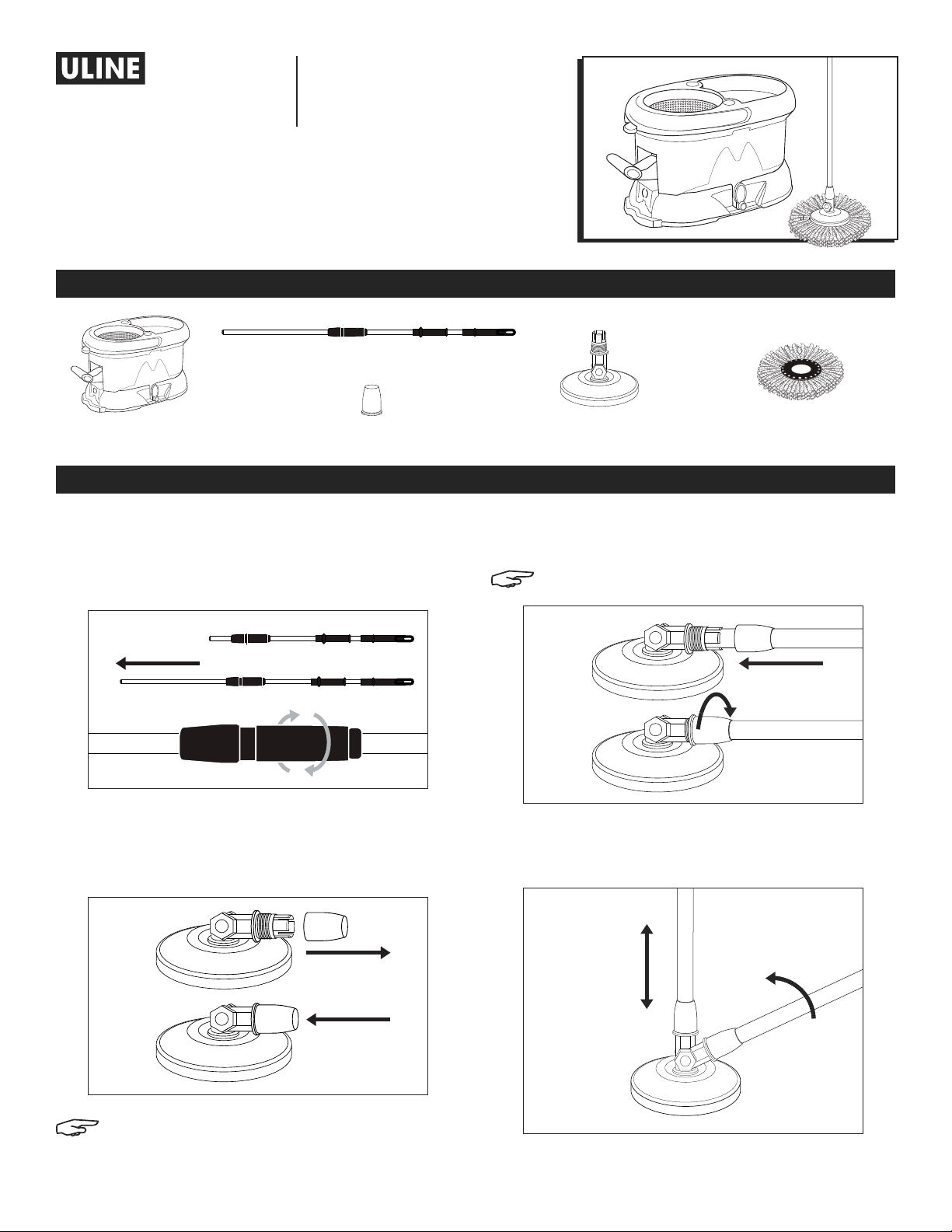
PAGE 6 OF 9 0721 IH-6526
EXPRIMIR EL TRAPEADOR
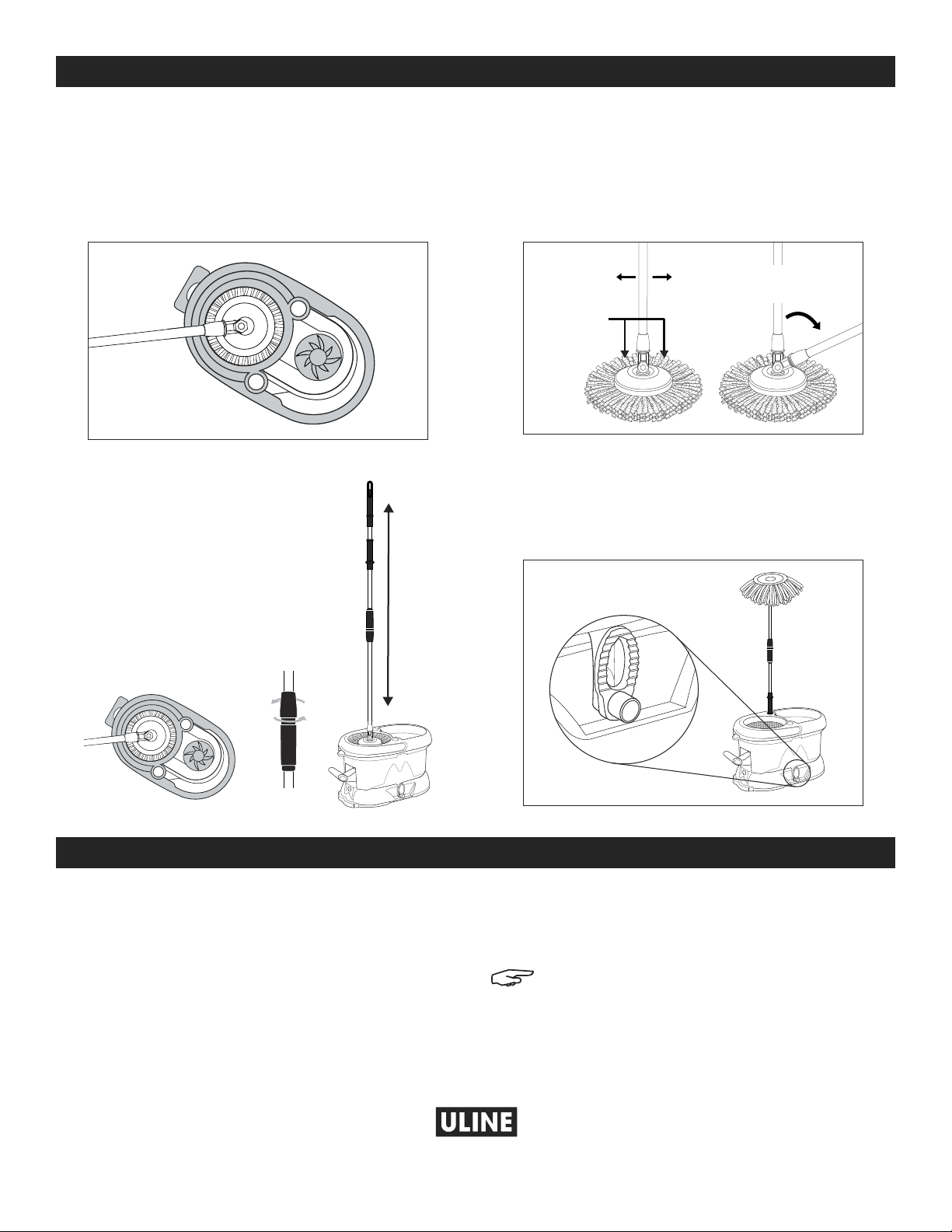
1. Coloque la cabeza del trapeador en la canasta de
acero inoxidable y bombee el pedal hasta que se
alcance el nivel de secado deseado. (Vea Diagrama 11)
Vea el siguiente paso para un método opcional
de exprimido.
EXPRIMIR EL TRAPEADOR (OPCIONAL)
1. Coloque la cabeza del trapeador en
la canasta de acero inoxidable. Gire
el asa del trapeador a la posición "on"
y bombee con el asa hacia abajo
para girar la cabeza del trapeador.
Gire para alcanzar el nivel de secado
deseado. (Vea Diagrama 12)
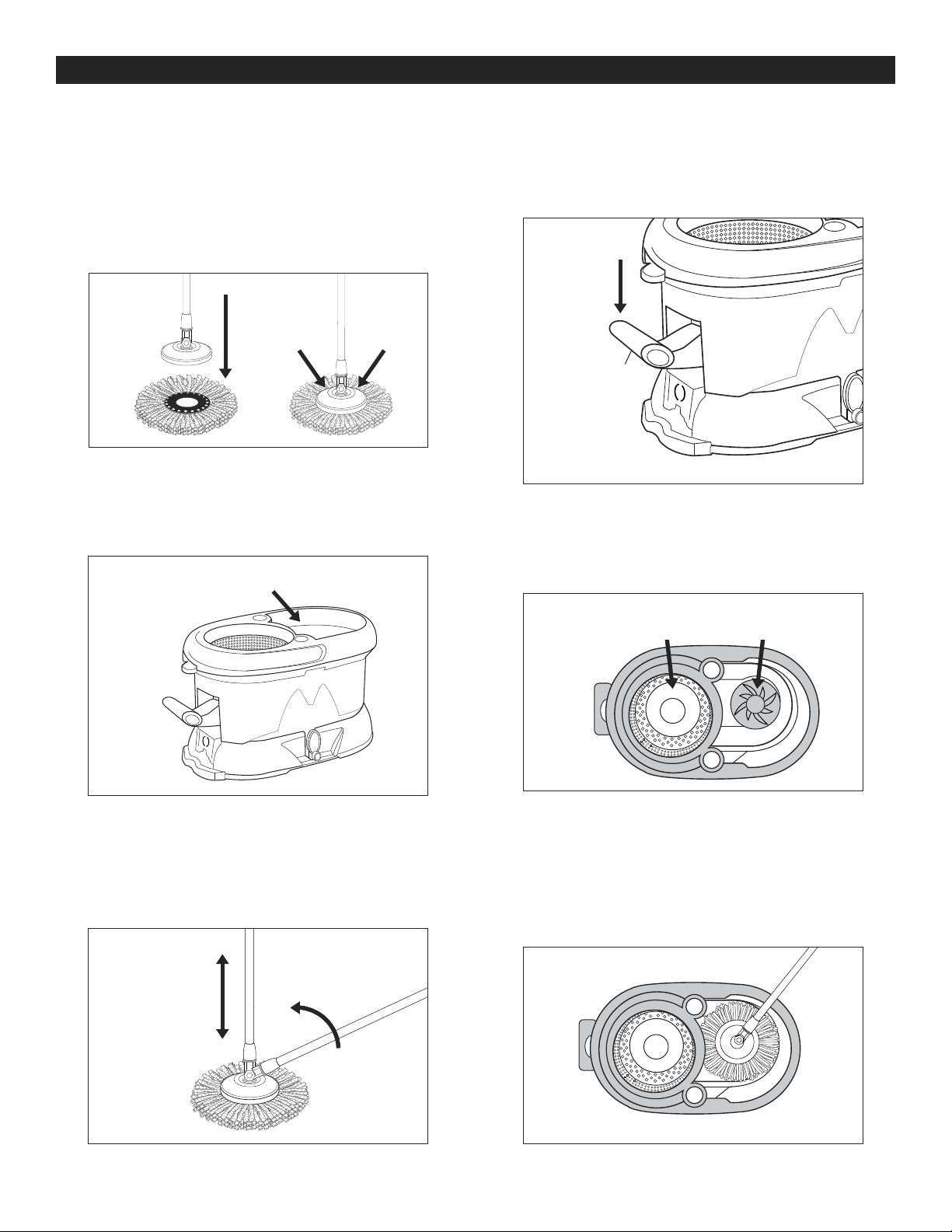
TRAPEAR
1. Coloque la cabeza de trapeador de microfibra plana
en el piso y pise cada lado del aditamento de la
cabeza del trapeador con los pies. Empuje el asa del
trapeador a la derecha o izquierda para liberar de
la posición de bloqueo. El trapeador está listo para
usarse. (Vea diagrama 13)
ALMACENAMIENTO
1. Exprima el trapeador. Vacíe la cubeta utilizando el
desagüe en un lado. Pliegue el asa del trapeador y
bloquéela. Coloque el trapeador en el soporte de
la cubeta. (Vea Diagrama 14)
CONTINUACIÓN DE OPERACIÓN
CÓMO RETIRAR Y CUIDAR LA CABEZA DE TRAPEADOR DE MICROFIBRA
Diagrama 12
Diagrama 13
Diagrama 14
1. Para remover la cabeza de trapeador de microfibra,
jálela con sus manos; o mientras el trapeador se
encuentre en posición vertical de bloqueo, pise la
parte de microfibra de la cabeza del trapeador
(no el aditamento de acero inoxidable) que se
encuentra perpendicular con el movimiento de la
bisagra y empuje el asa alejándose del cuerpo.
2. Lave la cabeza de trapeador de microfibra a mano
con agua y jabón o colóquela en la lavadora con
detergente.
NOTA: Siempre permita que su cabeza de
trapeador de microfibra se seque al aire. No
utilice secadora.
Bombee
el asa
hacia
abajo
Pie aquí
El Trapeador se
encuentra en posición
desbloqueda
Desagüe
Diagrama 11
00-295-551