Ublox EVK-M8T User manual

EVK-M8T
Evaluation Kit
User Guide
Abstract
This document describes the structure and use of the EVK-M8T e
valuation
kit and provides information for evaluating and testing u-
blox M8
positioning technology for timing and raw data applications.
www.u
-blox.com
UBX
-14041540 - R04

EVK-M8T - User Guide
UBX-14041540 - R04 Page 2 of 24
Document Information
Title EVK-M8T
Subtitle Evaluation Kit
Document type User Guide
Document number UBX-14041540
Revision and Date R04 23-Mar-2016
Document status Early Production Information
Document status explanation
Objective Specification Document contains target values. Revised and supplementary data will be published later.
Advance Information Document contains data based on early testing. Revised and supplementary data will be published later.
Early Production Information Document contains data from product verification. Revised and supplementary data may be published later.
Production Information Document contains the final product specification.
This document applies to the following products:
Product name Type number Hardware Version ROM/FLASH version PCN reference
EVK-M8T EVK-M8T-0-00 A Flash FW 3.01 TIM 1.10 UBX-16005636
u-blox reserves all rights to this document and the information contained herein. Products, names, logos and designs described herein
may in whole or in part be subject to intellectual property rights. Reproduction, use, modification or disclosure to third parties of this
document or any part thereof without the express permission of u-blox is strictly prohibited.
The information contained herein is provided “as is” and u-blox assumes no liability for the use of the information. No warranty, either
express or implied, is given, including but not limited, with respect to the accuracy, correctness, reliability and fitness for a particular
purpose of the information. This document may be revised by u-blox at any time. For most recent documents, visit www.u-blox.com.
Copyright © 2016, u-blox AG.
u-blox® is a registered trademark of u-blox Holding AG in the EU and other countries. ARM® is the registered trademark of ARM Limited
in the EU and other countries.

EVK-7 / EVK-M8 User Guide
UBX-14041540 - R04 Early Production Information Preface
Page 3 of 24
Preface
Using this guide
This guide assumes, the user has basic computer skills and is familiar with the Windows Graphical User Interface
(GUI) and GNSS receiver environments.
The following symbols are used in the document to highlight information:
A warning symbol indicates actions that could negatively impact or damage the device.
An index finger points out key information pertaining to device operation and performance.
Warnings and certifications
CAUTION! IN THE UNLIKELY EVENT OF A FAILURE IN THE INTERNAL PROTECTION
CIRCUITRY THERE IS A RISK OF AN EXPLOSION WHEN
CHARGING FULLY OR
PARTIALLY DISCHARGED BATTERIES. REPLACE THE BATTERY IF
IT NO LONGER
HAS SUFFICIENT CHARGE FOR UNIT OPERATION. CONTROL THE BATTERY BEFORE
USING IF THE DEVICE HAS NOT BEEN OPERATED FOR AN EXTENDED PERIOD OF
TIME.
Products marked with this lead-
free symbol on the product label comply with the
“Directive 2002/95/EC of the European Parliament and the Council on the Restriction of
Use of certain Hazardous Substances in Electrical and Electronic Equipment” (RoHS).
EVK-M8T evaluation kit is RoHS compliant and green (no halogens).

EVK-7 / EVK-M8 User Guide
UBX-14041540 - R04 Early Production Information Contents
Page 4 of 24
Contents
Preface ................................................................................................................................3
Using this guide............................................................................................................................................... 3
Warnings and certifications ............................................................................................................................. 3
Contents..............................................................................................................................4
1Product description ......................................................................................................6
1.1 Overview .............................................................................................................................................. 6
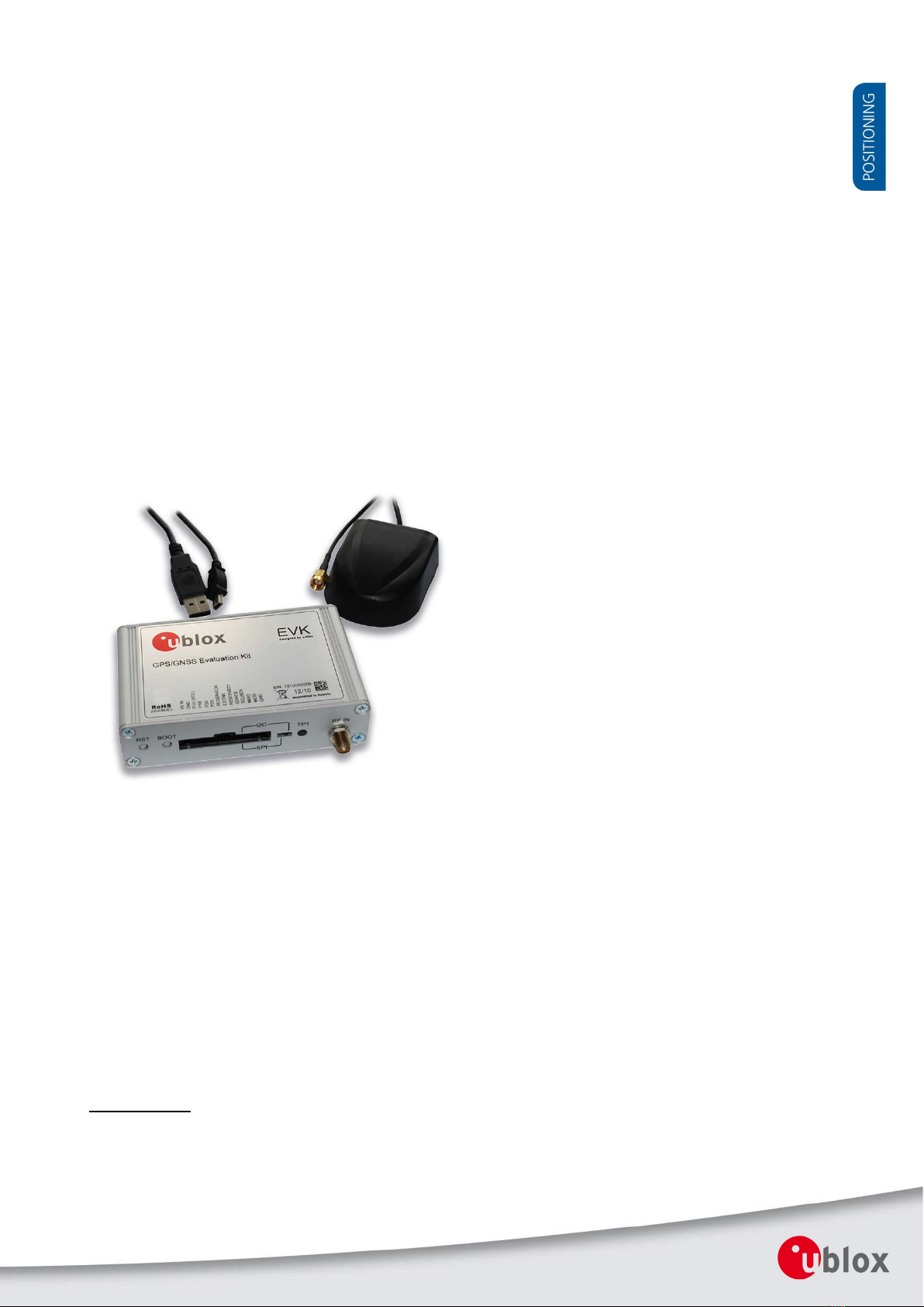
1.2 Kit includes........................................................................................................................................... 6
1.3 Software and documentation ............................................................................................................... 6
1.3.1 u-center GNSS evaluation software ............................................................................................... 6
1.4 System requirements ............................................................................................................................ 6
2Specifications................................................................................................................7
3Getting Started.............................................................................................................8
3.1 Software installation ............................................................................................................................. 8
3.2 Hardware installation............................................................................................................................ 8
3.3 Serial port default configuration ........................................................................................................... 8
4Device description........................................................................................................9
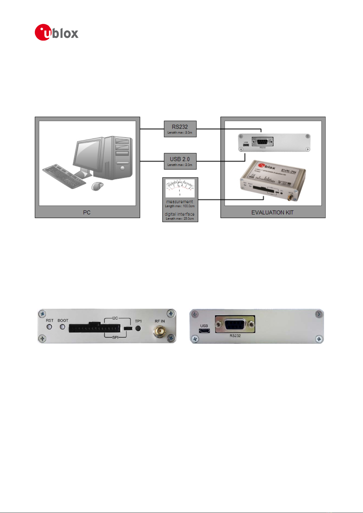
4.1 Interface connection and measurement ................................................................................................ 9
4.2 Active antenna ..................................................................................................................................... 9
4.3 Evaluation unit...................................................................................................................................... 9
4.3.1 Antenna connector ..................................................................................................................... 10
4.3.2 USB ............................................................................................................................................. 10
4.3.3 UART........................................................................................................................................... 10
4.3.4 RST button .................................................................................................................................. 10
4.3.5 Safe boot button......................................................................................................................... 10
4.3.6 Slide Switch................................................................................................................................. 10
4.3.7 Test Connector............................................................................................................................ 11
4.3.8 LED ............................................................................................................................................. 12
4.3.9 Backup Battery ............................................................................................................................ 12
4.3.10 GNSS Configuration .................................................................................................................... 12
5Measuring tracking current .......................................................................................13
6Testing Power Save Mode .........................................................................................14
7Block diagram.............................................................................................................15
8Board layout ...............................................................................................................16

EVK-7 / EVK-M8 User Guide
UBX-14041540 - R04 Early Production Information Contents
Page 5 of 24
9Schematic....................................................................................................................18
10 Battery replacement...................................................................................................19
11 Troubleshooting .........................................................................................................20
12 Common evaluation pitfalls ......................................................................................22
Related documents...........................................................................................................23
Revision history................................................................................................................23
Contact..............................................................................................................................24

EVK-7 / EVK-M8 User Guide
UBX-14041540 - R04 Early Production Information Product description
Page 6 of 24
1Product description
1.1 Overview
EVK-M8T evaluation kit makes evaluating the high performance u-blox M8T positioning products simple. The
built-in USB interface provides both power supply and high-speed data transfer, and eliminates the need for an
external power supply. The u-blox evaluation kits are compact, and their user friendly interface and power supply
make them ideally suited for use in laboratories, vehicles and outdoor locations. Furthermore, they can be used
with a PDA or a notebook PC, making them the perfect companion through all stages of design-in projects.
Evaluation Kit Description Suitable for
EVK-M8T u-blox M8 Timing GNSS Evaluation Kit NEO-M8T, LEA-M8T
Table 1: List of products supported by EVK-M8T evaluation kit
1.2 Kit includes
•Evaluation unit
•USB cable
•Active GPS / GLONASS / BeiDou antenna with 3 m cable
•Extra Battery RENATA CR2450
•Quick Start card
1.3 Software and documentation
The EVK installation software (and documentation) package can be downloaded from the Web; see the Quick
Start card for the URL.
1.3.1 u-center GNSS evaluation software
The installation software includes u-center, an interactive tool for configuration, testing, visualization and data
analysis of GNSS receivers. It provides useful assistance during all phases of a system integration project.
1.4 System requirements
•PC with USB interface
•Operating system: Windows Vista onwards (x86 and x64 versions)
•USB drivers are provided in the evaluation kit installation software

EVK-7 / EVK-M8 User Guide
UBX-14041540 - R04 Early Production Information Specifications
Page 7 of 24
2Specifications
Parameter Specification
Serial Interfaces 1 USB V2.0
1 RS232, max. baud rate 921,6 kBd
DB9 +/- 12 V level
14 pin – 3.3 V logic
1 DDC (I2C compatible) max. 400 kHz
1 SPI – clock signal max. 5,5 MHz – SPI DATA max. 1 Mbit/s
Timing Interfaces 2 Time-pulse outputs
1 Time-mark input
Dimensions 105 x 64 x 26 mm
Power Supply 5V via USB or external powered via extra power supply
pin 14 (V5_IN) 13 (GND)
Normal Operating temperature -40°C to +65°C
Table 2: EVK-M8T specifications

EVK-7 / EVK-M8 User Guide
UBX-14041540 - R04 Early Production Information Getting Started
Page 8 of 24
3Getting Started
3.1 Software installation
Installation of the EVK-M8T software and documentation requires Internet access.
Choose Software only or Software and documentation installation package from u-blox website. Once the zip
file is downloaded and unzipped, unzip the file in Tools folder and double-click the extracted exe file.
The software components will be installed on your system and placed under the “u-blox” folder in the “Start
Programs” menu.
3.2 Hardware installation
1. Connect the unit to a PC running Microsoft Windows. Options:
•USB: Connect via USB port.
•UART: Connect via RS232. Set slide switch to I2C.
•SPI / I2C compliant DDC: Connect corresponding pins (see Table 5 for pin description). Set slide
switch accordingly to SPI or I2C.
Press the RST button after changing the switch.
2. The device must always have power, either via USB on the back or the V5_IN input on the front.
3. Connect the GNSS antenna to the evaluation unit and place the antenna in a location with good sky view.
4. Start the u-center GNSS Evaluation Software and select corresponding COM port and baud rate.
Refer to the u-center User Guide [5] for more information.
3.3 Serial port default configuration
Parameter Description Remark
UART Port 1, Input UBX and NMEA protocol at 9’600 Bd
UART Port 1, Output UBX and NMEA protocol at 9’600 Bd Only NMEA messages are activated
USB, Input UBX and NMEA protocol
USB, Output UBX and NMEA protocol Only NMEA messages are activated
Table 3: Default configuration

EVK-7 / EVK-M8 User Guide
UBX-14041540 - R04 Early Production Information Device description
Page 9 of 24
4Device description
4.1 Interface connection and measurement
For connecting the EVK to a PC, use a standard SUBD-9 cable and the included Micro-USB cable.
Additional measurement equipment can be connected to the front connector.
Figure 1: Connecting the unit for power supply and communication
4.2 Active antenna
EVK-M8 evaluation kits include a GPS / GLONASS / BeiDou antenna with a 3 m cable. It is possible to connect
various active and passive GNSS antennas with SMA connectors to the evaluation unit.
The recommended maximum antenna supply current for active antennas is 30 mA.
4.3 Evaluation unit
Figure 2 shows the front and the rear panel of the EVK-M8T evaluation unit.
Front panel
Rear panel
Figure 2: EVK-M8T evaluation unit – front and rear panels

EVK-7 / EVK-M8 User Guide
UBX-14041540 - R04 Early Production Information Device description
Page 10 of 24
4.3.1 Antenna connector
An SMA female jack is available on the front side (see Figure 2) of the evaluation unit for connecting an active or
passive antenna. DC voltage at the RF input is 3.3 V. The internal short circuit protection limits the maximum
current to 60 mA. Please note that the 30 mA maximum supply current for active antenna stays the same. This
pin is also ESD protected.
The u-blox NEO-M8T module used in the EVK-M8T incorporates an additional, off-chip LNA.
The connector is only to be used with a GNSS antenna or simulator. Do not connect this
equipment to cable distribution systems.
4.3.2 USB
A USB V2.0 compatible serial port is featured for data communication and power supply.
4.3.3 UART
The evaluation unit includes an RS232 port for serial communication that is compatible with PC serial ports.
Connect using a straight RS232 serial cable with male and female connectors to the port on your PC. The
maximum cable length is < 3.0 meters. To configure the RS232 port, use the CFG-PRT command in the u-center
application. The maximum operating baud rate is 921.6 kBd.
If you are using a USB to RS232 adaptor cable, you can connect it directly to the evaluation kit RS232 port.
The 9-pin D-SUB female connector is assigned as listed in Table 4:
Pin Nr. Assignment
1 Time-pulse 1 output (RS-232 levels)
2 TXD, GNSS Transmit Data, serial data to DTE
3 RXD, GNSS Receive Data, serial data from DTE
4 Optional time-mark input (RS-232 levels) using EXTINT0 (internal jumper J6 fitment required)
5 GND
6 not connected
7 Time-pulse 1 output (RS-232 levels)
8, 9 not connected
Table 4: SUB-D9 Connector pin description for EVK-M8T
4.3.4 RST button
The RST button on the front panel resets the unit. To avoid an inadvertent reset, the button is recessed.
4.3.5 Safe boot button
This is used to set the unit in safe boot mode. In this mode the receiver executes only the minimal functionality,
such as updating new firmware into the SQI flash. In order to set the receiver in safe boot mode please follow
these steps.
1. Press the BOOT button and keep holding
2. Press the RST button
3. Release the RST button
4. Release the BOOT button
5. If the UART interface has to be used, the training sequence has to be sent to the receiver.
The training sequence is a transmission of 0x55 55 at the baud rate of 9600 Bd. Wait for at least 100
milliseconds before the interface is ready to accept commands.
4.3.6 Slide Switch
Use the slide switch on the front panel to choose between I2C (and UART) and SPI communication ports. You
must reset the unit by pressing the RST button when the slide switch has been changed.

EVK-7 / EVK-M8 User Guide
UBX-14041540 - R04 Early Production Information Device description
Page 11 of 24
1. I2C – In this selection the EVK operates with the UART (RS232 DB9 – rear panel or the 3.3 V level TxD
(MISO), RxD (MOSI) at the front panel). Also the communication via 3.3 V DDC interface (I2C) is
selected.
2. SPI – In this selection the EVK operates only with the SPI interface. RS232 (DB9) is switched off.
4.3.7 Test Connector
This 14-pin test-connector provides additional functionality to the EVK, allowing access to the interface pins and
an ability to measure the current used by the EVK. All pins are ESD protected.
For accurate measurements, it is recommended to use a cable of at most 1 meter in length. Figure 3 shows an
example of a power supply connected to the test connector by using standard adapter cables from the
manufacture Hirschmann. Figure 4 shows an example for overall current measurement. When connecting the
3.3 V digital interfaces RS232, SPI and DDC to your application, a cable length less than 25 cm is recommended.
PIN Nr.
PIN NAME I/O LEVEL DESCRIPTION
14 V5_IN I 4.75 V – 5.25 V Power input – can be used instead of USB
13 GND I - Common ground pin
12 P1A (VCC) O 3.3 V
Power output – max. current supply 100 mA
1Ω1% resistor for over-all current measurement to pin 11 (P1B)
NOTE: the current includes also SQI Flash, LNA
11 P1B O Second connection for over-all current measurement (see Figure 5)
10 P2A O 3.0 V
Battery output (unloaded)
100 Ω1% resistor for battery backup current measurement to pin 9 (P2B)
NOTE: There is a current protection to 3 mA. See circuit in figure 7 (D2, D4,
R29)
9 P2B O Second junction for battery backup current measurement
8 TIMEPULSE 1 O 3.3V Time pulse 1 (internally buffered output)
7 EXTINT0 I 3.3 V External interrupt or time-mark input
6 TIMEPULSE 2 O 3.3 V Time pulse 2 (internally buffered output)
5 SDA / CS I/O 3.3 V
If slide switch on I2C, then DDC interface selected; Function: data input / output
If slide switch on SPI, then SPI interface selected; chip select input – LOW
ACTIVE
4 SCL / SCK I/O 3.3 V Clock input / output
3 TxD / MISO I/O 3.3 V If slide switch on I2C, then DDC interface selected / UART TxD (3.3V Level)
If slide switch on SPI, then SPI interface selected; Master in Slave out (MISO)
2 RxD / MOSI I/O 3.3 V If slide switch on I2C, then DDC interface selected / UART RxD (3.3V Level)
If slide switch on SPI, then SPI interface selected; Master out Slave in (MOSI)
1 GND I - Common ground pin
Table 5: Connector pin description for EVK-M8T (pins numbered from right to left on the front panel)
Figure
3: Example 5V DC power supply
V5_IN
GND
GND
V5_IN
Hirschmann
Part Nr.: 934160100

EVK-7 / EVK-M8 User Guide
UBX-14041540 - R04 Early Production Information Device description
Page 12 of 24
4.3.8 LED
On the front panel of the unit, a single blue LED shows the time pulse 1 signal. The LED starts flashing one pulse
per second during a GNSS fix. If there is no GNSS fit, the LED will only light, without flashing.
4.3.9 Backup Battery
There is a backup battery in the unit. This is necessary to store orbital information between operations and to
enable faster start-up. It is a RENATA 3.0 V Li / MnO² battery of the type CR2450. The battery has a rated
capacity of 540 mA. The battery operating temperature range is -40° C to +85° C.
CAUTION! RISK OF EXPLOSION IF BATTERY IS REPLACED BY AN INCORRECT TYPE. DISPOSE OF
USED BATTERIES ACCORDING TO THE INSTRUCTIONS!
4.3.10 GNSS Configuration
The EVK-M8T supports GPS, QZSS, Galileo, GLONASS, and BeiDou.
The GNSS to be used can be configured on u-center (View Messages View then UBX-CFG-GNSS). For more
information, refer to the u-center User Guide [5], the u-blox 8 / u-blox M8 Receiver Description including
Protocol Specification [4].

EVK-7 / EVK-M8 User Guide
UBX-14041540 - R04 Early Production Information Measuring tracking current
Page 13 of 24
5Measuring tracking current
To measure the tracking current with EVK-M8T, follow these steps:
1. Connect a true RMS voltmeter across P1A (VCC) and P1B of the front connector. (see Figure 4)
2. Wait 12 minutes to download all GNSS orbital data, or download all the Aiding Data via the AssistNow
Online service
3. Read the voltage (and average if necessary) on the voltmeter and convert to current (1 mV equals 1 mA)
4. Perform the test with good signals and clear sky view to ensure that the receiver can acquire the satellite
signals.
The overall current measurement also includes the internal SQI flash. For ROM based products the current
will be lower.
For more details see the circuit in Figure 7.
Figure
4: Example – tracking current measurement
Hirschmann
Part Nr.: 934160100
P1A (VCC)
P1B
P1B
P1A (VCC)

EVK-7 / EVK-M8 User Guide
UBX-14041540 - R04 Early Production Information Testing Power Save Mode
Page 14 of 24
6Testing Power Save Mode
When testing Power Save Mode with EVK-M8, observe the following points:
•When configuring Power Save Mode you must set up the parameters using the CFG-PM2 message first and
then enable Power Save Mode using CFG-RXM. The Configuration view or Messages view of the u-center
evaluation software can be used to do this. When enabling the mode using CFG-RXM, always save the
configuration by checking the “save configuration” box in u-center otherwise the configuration will be lost.
•Communications to the evaluation kit must be via the UART, I2C or SPI (not USB).
•The evaluation kit can be supplied via the USB connector or via V5_IN at the front panel connector. Do not
connect the USB cable to the PC! This can be done by either connecting a USB cable from the evaluation kit
to a USB hub, or by using a USB power connector.
•When altering the Power Save Mode configuration, first disable the mode using CFG- RXM (remember to
enable “save configuration” again), before changing the CFG-PM2 parameters. Then re-enable Power Save
Mode.
For more information, refer to the u-blox 8 / u-blox M8 Receiver Description including Protocol
Specification [4].

EVK-7 / EVK-M8 User Guide
UBX-14041540 - R04 Early Production Information Block diagram
Page 15 of 24
7Block diagram
Figure
5: EVK-M8T block diagram

EVK-7 / EVK-M8 User Guide
UBX-14041540 - R04 Early Production Information Board layout
Page 16 of 24
8Board layout
Figure 6 shows the EVK-M8T board layout (PCB Version A). See Table 6 for the component list of the EVB.
Figure
6: EVB-M8T layout

EVK-7 / EVK-M8 User Guide
UBX-14041540 - R04 Early Production Information Board layout
Page 17 of 24
PART DESCRIPTION
A1
GPS RECEIVER U-BLOX NEO-M8T-0-00 -40/+85C
BT1
BATTERY HOLDER RENATA CR2450N 3V
C1 C11 C13 C22
CAP CER X5R 0603 1U0 10% 6.3V
C2 C4 C6 C7 C8 C10 C14 C16 C19
CAP CER X7R 0603 100N 10% 10V
C3 C25
CAP CER X5R 1210 10U 10% 10V
C5
CAP CER X7R 0402 1N0 10% 16V
C9 C12
CAP CER X7R 0603 10N 10% 25V
C21
CAP CER COG 0402 22P 5% 25V
C24
CAP CER X5R 0402 100N 10% 10V
D1 D2 D4 D5
SURFACE MOUNT SCHOTTKY BARRIER RECTIFIER SS14 1A -55/+125C
D3 R17 R18 R20 R21 R22 R23
ESD PROTECTION FOR HIGH SPEED LINES, TYCO, 0.25PF, PESD0402-140 -55/+125C
DS1
LED OSRAM HYPER MINI TOPLED LB M673-L1N2-35 BLUE 0.02A
FB1
FERRITE BEAD MURATA BLM15HD 0402 1000R@100MHZ
J1
CON USB RECEPTACLE MICRO B TYPE SMD – MOLEX 47346-0001 – TID60001597 30V 1A
J2
CON SMA SMD STRAIGHT JACK 11.4MM HEIGHT WITHOUT WASHER AND NUT
J3 9 POLE SUBD CONNECTOR FEMALE
J4
14PIN 90\xB0 2.54MM PITCH DISCONNECTABLE CRIMP CONNECTOR -40/+85C
J6
CON 1-ROW THT 100MIL GRID 2PINS 0.64MM SQUARE 6.1MM HEIGHT
L2
IND MURATA LQW15A 0402 120N 5% 0.64A -55/+125C
Q1
MBT3906DW1T1G DUAL GENERAL PURPOSE TRANSISTOR 0.2A 0.15W -40/+125C
R1
RES THICK FILM CHIP 1206 10R 5% 0.25W
R2 R6 R11
RES THICK FILM CHIP 0603 100R 5% 0.1W
R3 R8 R14 R15 R19
VARISTOR BOURNS MLE SERIES CG0402MLE-18G 18V
R4 R5
RES THICK FILM CHIP 0603 22R 5% 0.1W -55/+125C
R7
RES THICK FILM CHIP 0603 1R0 5% 0.1W
R9 R28
RES THICK FILM CHIP 0603 51R 1% 0.063W
R10
RES THICK FILM CHIP 0402 220R 5% 0.1W
R12
RES THICK FILM CHIP 0402 2K2 5% 0.1W
R13 R24 R27
RES THICK FILM CHIP 0603 100K 5% 0.1W
R29 RES THICK FILM CHIP 0603 1K0 5% 0.1W
S1 S2
SWITCH SPST ON 1POL TYCO -40/+85C
S3
2 WAY SUB-MINIATURE SLIDE SWITCH SMD JS SERIES – SPDT -40/+85C
U1
USB DATA LINE PROTECTION ST USBLC6-2SC6 SOT23-6
U2 U4
LOW DROPOUT REGULATOR LINEAR LT1962 MS8 3.3V 0.3A
U3 U5 U9
TINY LOGIC UHS BUFFER OE_N ACTIVE LOW FAIRCHILD NC7SZ125 SC70
U6
RS-232 TRANSCEIVER 1MBIT 3-5,5VOLT TRSF3223 – VQFN20 5.5V 5.5V -40/+85C
U7
TINY LOGIC ULP-A 2-INPUT AND GATE 1.45X1.0 6-LEAD MICROPAK -40/+85C
Table 6: EVB-M8T component list

EVK-7 - User Guide
UBX-14041540 - R04 Early Production Information Schematic
Page 18 of 24
9Schematic
Figure 7: Schematic EVK-M8T: DNI=TRUE in the schematic means: Component not installed

EVK-7 - User Guide
UBX-14041540 - R04 Early Production Information Battery replacement
Page 19 of 24
10 Battery replacement
To replace the battery (Number 5 in Figure 8), open the unit (unscrew four screws on the front panel).
Figure 8: EVK-M8T battery location

EVK-M8T - User Guide
UBX-14041540 - R04 Early Production Information Troubleshooting
Page 20 of 24
11 Troubleshooting
My application (e.g. u-center) does not receive anything
Check whether the blue LED on the evaluation unit is blinking. Also make sure that the USB cable is properly
connected to the evaluation unit and the PC. By default, the evaluation unit outputs NMEA protocol on Serial
Port 1 at 9600 Bd, or on the USB.
My application (e.g. u-center) does not receive all messages
When using UART, make sure the baud rate is sufficient. If the baud rate is insufficient, GNSS receivers based on
u-blox M8 GNSS technology will skip excessive messages. Some serial port cards/adapters (i.e. USB to RS232
converter) frequently generate errors. If a communication error occurs while u-center receives a message, the
message will be discarded.
My application (e.g. u-center) loses the connection to the GNSS receiver
u-blox M8 positioning technology and u-center have an autobauding feature. If frequent communication errors
occur (e.g. due to problems with the serial port), the connection may be lost. This happens because u-center and
the GNSS receiver both autonomously try to adjust the baud rate. Do not enable the u-center autobauding
feature if the GNSS receiver has the autobauding flag enabled.
The COM port does not send any messages
Be sure that the slide switch at the front panel is set to I2C and not SPI. In SPI Mode the RS232 pins on the DB9
connector are switched off and the RxD and TxD output at the front panel are used for SPI (MISO, MOSI).
NOTE: After changing the slide switch, always reset the EVK, otherwise the change will not take place.
Some COM ports are not shown in the port list of my application (e.g. u-center)
Only the COM ports that are available on your computer will show up in the COM port drop down list. If a COM
Port is gray, another application running on this computer is using it.
The position is off by a few dozen meters
u-blox M8 GNSS technology starts up with the WGS84 standard GNSS datum. If your application expects a
different datum, you’ll most likely find the positions to be off by a few dozen meters. Don’t forget to check the
calibration of u-center map files.
The position is off by hundreds of meters
Position drift may also occur when almanac navigation is enabled. The satellite orbit information retrieved from
an almanac is much less accurate than the information retrieved from the ephemeris. With an almanac only
solution, the position will only have an accuracy of a few kilometers but it may start up faster or still navigate in
areas with obscured visibility when the ephemeris from one or several satellites have not yet been received. The
almanac information is NOT used for calculating a position, if valid ephemeris information is present, regardless
of the setting of this flag.
In NMEA protocol, position solutions with high deviation (e.g. due to enabling almanac navigation) can be
filtered with the Position Accuracy Mask. UBX protocol does not directly support this since it provides a position
accuracy estimation, which allows the user to filter the position according to his requirements. However, the
‘Position within Limits’ flag of the UBX-NAV-STATUS message indicates whether the configured thresholds (i.e. P
Accuracy Mask and PDOP) are exceeded.
TTFF times at startup are much longer than specified
At startup (after the first position fix), the GNSS receiver performs an RTC calibration to have an accurate internal
time source. A calibrated RTC is required to achieve minimal startup time.
Before shutting down the receiver externally, check the status in MON-HW in field ‘Real Time Clock Status’. Do
not shut down the receiver if the RTC is not calibrated.
The EVK-M8T does not meet the TTFF specification
Make sure the antenna has a good sky view. An obstructed view leads to prolonged startup times. In a well-
designed system, the average of the C/No ratio of high elevation satellites should be in the range of 40 dBHz to
Table of contents
Other Ublox Motherboard manuals

Ublox
Ublox EVK-JODY-W2 User manual

Ublox
Ublox XPLR-AOA User manual

Ublox
Ublox EVK-M8T-0-01 User manual

Ublox
Ublox EVK-NINA-B4 User manual

Ublox
Ublox EVK-ELLA-W1 User manual

Ublox
Ublox C93-M8E User manual

Ublox
Ublox EVK-M8L User manual

Ublox
Ublox EVK-R6 User manual

Ublox
Ublox EVK-M10QSAM User manual

Ublox
Ublox BMD-3 Series User manual

Ublox
Ublox EVK-M8QSAM User manual

Ublox
Ublox EVK BMD-345 User manual

Ublox
Ublox R41Z evaluation User manual

Ublox
Ublox EVK-R8 Series User manual

Ublox
Ublox EVK-M8 User manual

Ublox
Ublox EVK-JODY-W3 User manual

Ublox
Ublox XPLR-AOA-3 User manual

Ublox
Ublox EVK-ANNA-B112 User manual

Ublox
Ublox EVK-M8GZOE User manual

Ublox
Ublox EVK-R4 Series User manual