EVK-N2 - User guide
UBX-17005115 - R05 Starting up Page 5 of 18
1.2 EVK-N2 block diagram
Figure 2 shows the main interfaces and internal connections of the EVK-N2 evaluation kit:
SIM
card holder
(J300)
Reset
(SW303)
Power-on
(SW302)
ADP-N2
SARA-N2
module
42-pin DIL Board-to-Board Connector
(J101)
42-pin DIL Board-to-Board Connector
(J104)
EVB-WL3
GNSS
module
GNSS Adapter Board
RF
USB
UART / UART AUX
converter
Cellular USB
(UART / UART AUX)
(J501)
Cellular RS232
(UART)
(J500)
RS232
UART
converter UART
MiniUSB/DB9
switch
(SW403)
On-Board/B2B
switch
(SW401)
USB
Headset jack
(J303)
I2C
ANT
(J102)
Step - Down
Main power switch
(SW400)
12 V
(J400)
3.8 V
VCC jumper
(J404)
LDO
UART AUX
UART AUX switch
(SW510) VCC jumper
(J103)
1.8V / VCC
Level Translator
SARA-N2 Adapter Board
ADP-GNSS
Figure 2: Block diagram of EVK-N2 for SARA-N2 series modules
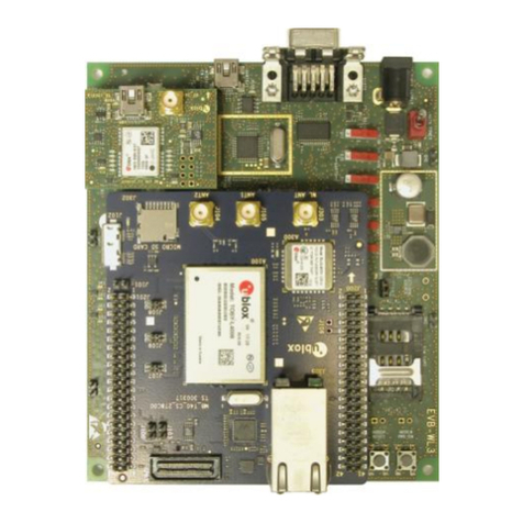
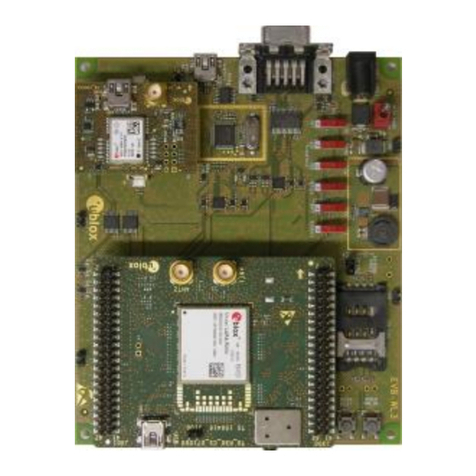
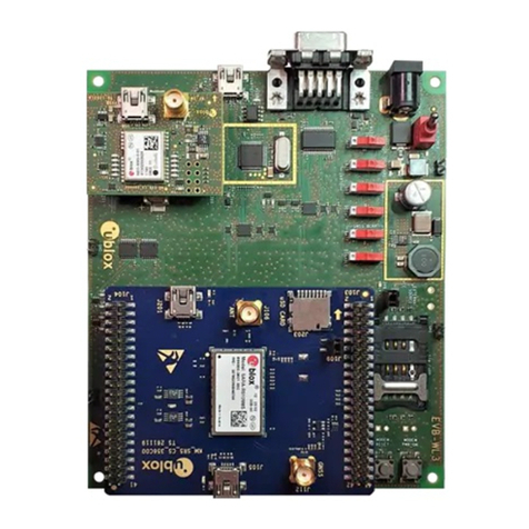
The EVK-N2 evaluation kit is formed by three boards:
The lower one, called EVB-WL3, contains the power supply and other peripherals for the SARA-N2
module (e.g. SIM card holder and Reset button).
The cellular adapter board, called ADP-N2, contains the SARA-N2 module, the cellular antenna
connector and the DIL connectors (J101 and J104).
The GNSS adapter board, called ADP-GNSS, contains the u-blox GNSS module, the GNSS antenna
connector and the USB connector for the GNSS module.
The boards are connected by means of male header board-to-board connectors provided on the
bottom of the adapter boards and their corresponding female connectors provided on top of the lower
board.
The SARA-N2 series pins are available on the Dual-In-Line male Board-to-Board connectors provided
on the top layer of the cellular Adapter Board (J101 and J104), which are pin-to-pin compatible to the
connectors on the bottom layer of the adapter board EVB-WL3.
Communication with the SARA-N2 module is provided through the Cellular RS232 DB9 connector
(J500) or the Cellular USB Mini-USB connector (J501), available on the EVB-WL3 board. The UART
interface of the SARA-N2 module is routed up to both connectors J500 and J501. The Mini-USB / DB9
slide switch (SW403) must be set according to the selected connector. The Cellular USB Mini-USB
connector (J501) provides also access to the secondary / auxiliary UART interface of the SARA-N2
module (see section 1.8).
The lower board (EVB-WL3) is designed also to be used with other u-blox cellular adapter boards. It
contains additional switches, jumpers, connectors, LEDs and parts that are partially described in
Figure 1 or in this document, because they are intended for use only with other u-blox cellular modules.
It is recommended to leave any additional connector unconnected and any additional switch in its
default configuration.
