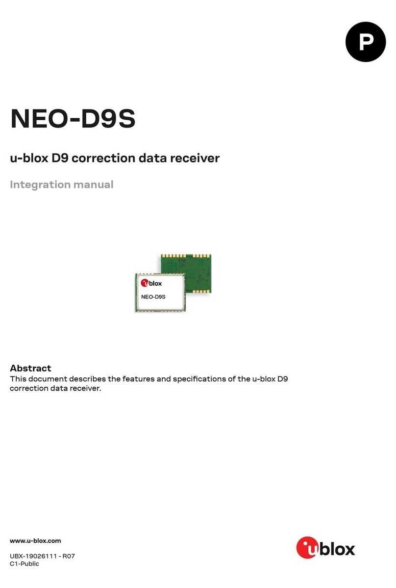
Ublox EVA-M8M Quick setup guide

EVA-M8M
u-blox M8 concurrent GNSS modules
Hardware Integration Manual
Abstract
This document describes the hardware features and specifications of
the cost effective EVA-
M8M concurrent GNSS modules featuring
the u-blox M8 positioning engine.
The EVA-M8M series boasts the industry’s smallest
form factor and
is a fully tested standalone solution that requires no host
integration.
The EVA-
M8M modules combine exceptional GNSS performance
with highly flexible power, design, and serial communication
options.
www.u
-blox.com
UBX
-14006179 - R01

EVA-M8M - Hardware Integration Manual
Document Information
Title EVA-M8M
Subtitle u-blox M8 concurrent GNSS modules
Document type Hardware Integration Manual
Document number UBX-14006179
Revision and date R01 30-Sep-2014
Document status Advance Information
Document status explanation
Objective Specification Document contains target values. Revised and supplementary data will be published later.
Advance Information Document contains data based on early testing. Revised and supplementary data will be published later.
Early Production Information Document contains data from product verification. Revised and supplementary data may be published later.
Production Information Document contains the final product specification.
This document applies to the following products:
Product name Type number ROM/FLASH version PCN reference
EVA-M8M EVA-M8M-0-00 ROM 2.01 / Flash FW 2.01 N/A
EVA-M8M EVA-M8M-1-00 ROM 2.01 / Flash FW 2.01 N/A
u-blox reserves all rights to this document and the information contained herein. Products, names, logos and designs described herein
may in whole or in part be subject to intellectual property rights. Reproduction, use, modification or disclosure to third parties of this
document or any part thereof without the express permission of u-blox is strictly prohibited.
The information contained herein is provided “as is” and u-blox assumes no liability for the use of the information. No warranty, either
express or implied, is given, including but not limited, with respect to the accuracy, correctness, reliability and fitness for a particular
purpose of the information. This document may be revised by u-blox at any time. For most recent documents, please visit
www.u-blox.com.
Copyright © 2014, u-blox AG
u-blox®is a registered trademark of u-blox Holding AG in the EU and other countries. ARM®is the registered trademark of ARM Limited in
the EU and other countries.
UBX-14006179 - R01 Advance Information Page 2 of 45

EVA-M8M - Hardware Integration Manual
Preface
u-blox Technical Documentation
As part of our commitment to customer support, u-blox maintains an extensive volume of technical
documentation for our products. In addition to our product-specific technical data sheets, the following manuals
are available to assist u-blox customers in product design and development.
•GPS Compendium:This document, also known as the GPS book, provides a wealth of information
regarding generic questions about GPS system functionalities and technology.
•Receiver Description including Protocol Specification: This document describes messages, configuration
and functionalities of the EVA-M8M software releases and receivers.
•Hardware Integration Manuals: These manuals provide hardware design instructions and information on
how to set up production and final product tests.
•Application Notes: These documents provide general design instructions and information that applies to all
u-blox GNSS positioning modules.
How to use this Manual
This manual has a modular structure. It is not necessary to read it from beginning to end.
The following symbols highlight important information within the manual:
An index finger points out key information pertaining to module integration and performance.
A warning symbol indicates actions that could negatively influence or damage the module.
Questions
If you have any questions about EVA-M8M integration, please:
•Read this manual carefully.
•Contact our information service on the homepage http://www.u-blox.com.
•Read the questions and answers on our FAQ database on the homepage.
Technical Support
Worldwide Web
Our website (http://www.u-blox.com) is a rich pool of information. Product information, technical documents
and helpful FAQ can be accessed 24 h a day.
By E-mail
If you have technical problems or cannot find the required information in the provided documents, contact the
closest Technical Support office. To ensure that we process your request as soon as possible, use our service pool
email addresses rather than personal staff email addresses. Contact details are at the end of the document.
Helpful Information when Contacting Technical Support
When contacting Technical Support please have the following information ready:
•Receiver type (e.g. NEO-7N-0-000), Datacode (e.g. 172100.0100.000) and firmware version (e.g. ROM1.0)
•Receiver/module configuration
•Clear description of your question or the problem (may include a u-center logfile)
•A short description of the application
•Your complete contact details
UBX-14006179 - R01 Advance Information Preface
Page 3 of 45

EVA-M8M - Hardware Integration Manual
Contents
Preface ................................................................................................................................3
Contents..............................................................................................................................4
1Hardware description ..................................................................................................7
1.1 Overview.............................................................................................................................................. 7
2Design-in.......................................................................................................................8
2.1 Power management ............................................................................................................................. 8
2.1.1 Overview....................................................................................................................................... 8
2.1.2 Power management configuration ................................................................................................ 9
2.2 Interfaces............................................................................................................................................ 10
2.2.1 UART interface............................................................................................................................ 10
2.2.2 Display Data Channel (DDC) Interface ......................................................................................... 10
2.2.3 SPI Interface ................................................................................................................................ 11
2.2.4 USB interface............................................................................................................................... 11
2.2.5 SQI Flash memory........................................................................................................................ 12
2.3 I/O Pins............................................................................................................................................... 13
2.3.1 Time pulse................................................................................................................................... 13
2.3.2 External interrupt ........................................................................................................................ 13
2.3.3 Active antenna supervisor............................................................................................................ 13
2.3.4 Electromagnetic interference on I/O lines..................................................................................... 14
2.4 Real-Time Clock (RTC) ........................................................................................................................ 14
2.4.1 RTC using a crystal ...................................................................................................................... 15
2.4.2 RTC derived from the system clock.............................................................................................. 15
2.4.3 RTC using an external clock......................................................................................................... 15
2.4.4 Time aiding ................................................................................................................................. 15
2.5 RF input.............................................................................................................................................. 15
2.5.1 Active Antenna............................................................................................................................ 16
2.5.2 Passive Antenna .......................................................................................................................... 16
2.5.3 Improved Jamming Immunity ...................................................................................................... 16
2.6 Safe Boot Mode (SAFEBOOT_N pin).................................................................................................... 17
2.7 RESET_N............................................................................................................................................. 17
2.8 Design-in checklist.............................................................................................................................. 18
2.8.1 General considerations................................................................................................................ 18
2.8.2 Schematic design-in for EVA-M8M.............................................................................................. 18
2.9 Pin description.................................................................................................................................... 19
2.10 Layout design-in checklist ............................................................................................................... 20
2.11 Layout............................................................................................................................................. 20
2.11.1 Footprint..................................................................................................................................... 21
2.11.2 Paste mask.................................................................................................................................. 21
2.11.3 Placement ................................................................................................................................... 21
UBX-14006179 - R01 Advance Information Contents
Page 4 of 45

EVA-M8M - Hardware Integration Manual
2.12 Migration considerations................................................................................................................. 22
2.12.1 C88-M8M - Evaluating EVA-M8M on existing NEO-xM sockets................................................... 22
2.13 EOS/ESD/EMI precautions................................................................................................................ 24
2.13.1 Electrostatic Discharge (ESD)........................................................................................................ 24
2.13.2 ESD protection measures............................................................................................................. 24
2.13.3 Electrical Overstress (EOS)............................................................................................................ 24
2.13.4 EOS protection measures............................................................................................................. 25
2.13.5 Applications with cellular modules .............................................................................................. 25
3Product handling & soldering....................................................................................27
3.1 Packaging, shipping, storage and moisture preconditioning ............................................................... 27
3.2 ESD handling precautions................................................................................................................... 27
3.3 Soldering............................................................................................................................................ 27
3.3.1 Soldering paste............................................................................................................................ 27
3.3.2 Reflow soldering ......................................................................................................................... 28
3.3.3 Optical inspection........................................................................................................................ 28
3.3.4 Repeated reflow soldering........................................................................................................... 28
3.3.5 Wave soldering............................................................................................................................ 28
3.3.6 Rework........................................................................................................................................ 28
3.3.7 Conformal coating ...................................................................................................................... 28
3.3.8 Casting........................................................................................................................................ 28
3.3.9 Use of ultrasonic processes.......................................................................................................... 28
4Product testing ...........................................................................................................29
4.1 Test parameters for OEM manufacturer.............................................................................................. 29
4.2 System sensitivity test ......................................................................................................................... 29
4.2.1 Guidelines for sensitivity tests...................................................................................................... 29
4.2.2 ‘Go/No go’ tests for integrated devices........................................................................................ 29
Appendix ..........................................................................................................................30
AReference schematics.................................................................................................30
A.1 Cost optimized circuit......................................................................................................................... 30
A.2 Best performance circuit with passive antenna.................................................................................... 31
A.3 Improved jamming immunity with passive antenna............................................................................. 32
A.4 Circuit using active antenna................................................................................................................ 33
A.5 USB self-powered circuit with passive antenna ................................................................................... 34
A.6 USB bus-powered circuit with passive antenna ................................................................................... 35
A.7 Circuit using 2-pin antenna supervisor................................................................................................ 36
A.8 Circuit using 3-pin antenna supervisor................................................................................................ 37
A.9 Design-in Recommendations in combination with cellular operation................................................... 38
BComponent selection .................................................................................................39
B.1 External RTC (Y1)................................................................................................................................ 39
B.2 RF band-pass filter (F1) ....................................................................................................................... 39
B.3 External LNA protection filter (F2)....................................................................................................... 40
UBX-14006179 - R01 Advance Information Contents
Page 5 of 45
EVA-M8M - Hardware Integration Manual
B.4 USB line protection (D1) ..................................................................................................................... 40
B.5 USB LDO (U2)..................................................................................................................................... 40
B.6 External LNA (U1) ............................................................................................................................... 40
B.7 Optional SQI Flash (U3)....................................................................................................................... 41
B.8 RF ESD protection diode (D2).............................................................................................................. 41
B.9 Operational amplifier (U6) .................................................................................................................. 41
B.10 Open-drain buffer (U4, U7 and U8)................................................................................................. 41
B.11 Antenna supervisor switch transistor (T1)........................................................................................ 41
B.12 Ferrite beads (FB1) .......................................................................................................................... 41
B.13 Feed-thru capacitors ....................................................................................................................... 42
B.14 Inductor (L) ..................................................................................................................................... 42
B.15 Standard capacitors ........................................................................................................................ 42
B.16 Standard resistors ........................................................................................................................... 42
Appendix ..........................................................................................................................43
CGlossary ......................................................................................................................43
Related documents...........................................................................................................44
Revision history................................................................................................................44
Contact..............................................................................................................................45
UBX-14006179 - R01 Advance Information Contents
Page 6 of 45

EVA-M8M - Hardware Integration Manual
1Hardware description
1.1 Overview
The EVA-M8M standalone concurrent GNSS modules feature the exceptional performance of the u-blox M8
positioning engine (GPS/QZSS, GLONASS, and BeiDou signals). The EVA-M8M series delivers high sensitivity and
minimal acquisition times in the ultra compact EVA form factor.
The EVA-M8M series is an ideal solution for cost and space-sensitive applications. It is easy to design-in, only
requiring an external GNSS antenna in most applications. The layout of the EVA-M8M modules is especially
designed to ease the customer’s design and limit near field interferences since RF and digital domains are kept
separated.
The EVA-M8M series uses a crystal oscillator for lower system costs. Like other u-blox GNSS modules, the
EVA-M8M uses components selected for functioning reliably in the field over the full operating temperature
range.
With dual-frequency RF front-end, the u-blox M8 concurrent GNSS engine is able to intelligently use the highest
amount of visible satellites from two GNSS (GPS, GLONASS and BeiDou) systems for reliable positioning. The
EVA-M8M series comes in two variants. The EVA-M8M-0 defaults to GPS/QZSS/GLONASS and fits global
applications, whereas EVA-M8M-1 defaults to GPS/QZSS/BeiDou making it the ideal module for China. The right
satellite constellations can be selected without touching software, and therefore reducing the design and testing
effort.
The EVA-M8M modules can be easily integrated in manufacturing, thanks to the QFN-like package and low
moisture sensitivity level. The modules are available in 500 pcs/reel, ideal for small production batches. The
EVA-M8M modules combine a high level of integration capability with flexible connectivity options in a miniature
package. This makes them perfectly suited for industrial and mass-market end products with strict size and cost
requirements. The DDC (I2C compliant) interface provides connectivity and enables synergies with u-blox cellular
modules.
The EVA-M8M modules are manufactured in ISO/TS 16949 certified sites and qualified as stipulated in the
JESD47 standard.
For applications needing firmware update capability or data logging, the EVA-M8M series must be
connected to an external SQI Flash memory. For more information about product features, see the
EVA-M8M Data Sheet [1].
To determine which u-blox product best meets your needs, see the product selector tables on the u-blox
website www.u-blox.com.
UBX-14006179 - R01 Advance Information Hardware description
Page 7 of 45

EVA-M8M - Hardware Integration Manual
2Design-in
In order to obtain good performance with a GNSS receiver module, there are a number of points that require
careful attention during the design-in. These include:
•Power Supply: Good performance requires a clean and stable power supply.
•Interfaces: Ensure correct wiring, rate and message setup on the module and your host system.
•Antenna interface: For optimal performance, seek short routing, matched impedance and no stubs.
•External LNA: With EVA-M8M an additional external LNA is mandatory if a passive antenna is used
to achieve the performance values as written in the EVA-M8M Data Sheet [1].
2.1 Power management
2.1.1 Overview
The EVA-M8M modules provide 4 supply pins: VCC, VCC_IO, V_BCKP and V_USB. They can be supplied
independently or tied together to adapt various concepts, depending on the intended application. The different
supply voltages are explained in the following subsections.
Figure 1 shows an example to supply the EVA-M8M modules when not using the USB interface. In this case, the
V_USB pin is connected to ground.
Figure 1: EVA-M8M power supply example
UBX-14006179 - R01 Advance Information Design-in
Page 8 of 45

EVA-M8M - Hardware Integration Manual
2.1.1.1 Main supply voltage (VCC)
During operation, the EVA-M8M modules are supplied through the VCC pin. It makes use of an internal DC/DC
converter for improved power efficiency. In a following step, built-in LDOs generate stabilized voltages for the
Core and RF domains of the chip respectively. The current at VCC depends heavily on the current state of the
system and is in general very dynamic.
Do not add any series resistance (< 0.2 Ω) to the VCC supply, as it will generate input voltage noise due
to the dynamic current conditions.
2.1.1.2 I/O supply voltage (VCC_IO)
The digital I/Os of the EVA-M8M modules can be supplied with a separate voltage from the host system
connected to the VCC_IO pin of the module. The wide range of VCC_IO allows seamless interfacing to standard
logic voltage levels. However, in most applications VCC_IO and VCC share the same voltage level and are tied
together. VCC_IO supplies also the RTC and the backup RAM (BBR) during normal operation.
VCC_IO must be supplied in order for the system to boot.
When running the firmware from the external SQI Flash most of the VDD_IO current is consumed by the
SQI bus.
2.1.1.3 Backup power supply (V_BCKP)
In the event of a power failure at VCC_IO, the backup domain is supplied by V_BCKP.
If no backup supply is available, connect V_BCKP to VCC_IO.
Avoid high resistance on the V_BCKP line: During the switch from main supply to backup supply, a
short current adjustment peak can cause high voltage drop on the pin with possible malfunctions.
If the RTC frequency is derived from the main clock, the V_BCKP pin also supplies the clock domain if
there is a power failure at VCC_IO, meaning that the V_BCKP current will also be higher. Ensure that
the capacity of the backup battery chosen meets your requirements.
2.1.1.4 USB interface power supply
V_USB supplies I/Os of the USB interface. If the USB interface is being used, the system can be either self-
powered, i.e. powered independently from the USB bus, or it can be bus-powered, i.e. powered through the
USB connection. In bus-powered mode, the system supply voltages need to be generated from the USB supply
voltage VBUS.
If the USB interface is not used, the V_USB pin must be connected to GND.
2.1.2 Power management configuration
Depending on the application, the power supply schematic will differ. Some examples are shown in the
following sections:
•Single supply voltage for VCC and VCC_IO, no backup supply see Appendix, Figure 13
•Separate supply voltages for VCC, VCC_IO and V_BCKP see Appendix, Figure 14
•Single supply voltage for VCC and VCC_IO, use of a backup supply see Appendix, Figure 16
For description of the different operating modes see the EVA-M8M Data Sheet [1].
UBX-14006179 - R01 Advance Information Design-in
Page 9 of 45

EVA-M8M - Hardware Integration Manual
2.2 Interfaces
The EVA-M8M modules provide UART, SPI and DDC (I2C compatible) interfaces for communication with a host
CPU. A USB interface is also available on dedicated pins (see section 2.2.4). Additionally, an SQI interface is
available for connecting the EVA-M8M modules with an optional external flash memory.
The UART, SPI and DDC pins are supplied by VCC_IO and operate at this voltage level.
Four dedicated pins can be configured as either 1 x UART and 1 x DDC or a single SPI interface selectable by
D_SEL pin. Table 1 below provides the port mapping details.
Pin 32 (D_SEL) = “high” (left open) Pin 32 (D_SEL) = “Low” (connected to GND)
UART TX SPI MISO
UART RX SPI MOSI
DDC SCL SPI CLK
DDC SDA SPI CS
Table 1: Communication Interfaces overview
It is not possible to use the SPI interface simultaneously with the DDC or UART interface.
For debugging purposes, it is recommended to have a second interface e.g. USB available that is
independent from the application and accessible via test-points.
For each interface, a dedicated pin can be defined to indicate that data is ready to be transmitted. The TX Ready
signal indicates that the receiver has data to transmit. A listener can wait on the TX Ready signal instead of
polling the DDC or SPI interfaces. The UBX-CFG-PRT message lets you configure the polarity and the number of
bytes in the buffer before the TX Ready signal goes active. The TX Ready function is disabled by default.
The TX Ready functionality can be enabled and configured by proper AT commands sent to the involved
u-blox cellular module supporting the feature. For more information see the GPS Implementation and
Aiding Features in u-blox wireless modules [5].
The TX Ready feature is supported on version LEON FW 7.xx and LISA-U2 01S and above.
2.2.1 UART interface
A UART interface is available for serial communication to a host CPU. The UART interface supports configurable
data rates with the default at 9600 baud. Signal levels are related to the VCC_IO supply voltage. An interface
based on RS232 standard levels (+/- 7 V) can be realized using level shifter ICs such as the Maxim MAX3232.
Hardware handshake signals and synchronous operation are not supported.
A signal change on the UART RX pin can also be used to wake up the receiver in Power Save Mode (see the
u-blox M8 Receiver Description Including Protocol Specification [2]).
2.2.2 Display Data Channel (DDC) Interface
An I2C compatible Display Data Channel (DDC) interface is available for serial communication with a host CPU.
The SCL and SDA pins have internal pull-up resistors sufficient for most applications. However, depending on the
speed of the host and the load on the DDC lines additional external pull-up resistors might be necessary. For
speed and clock frequency see the EVA-M8M Data Sheet [1].
To make use of DDC interface the D_SEL pin has to be left open.
The EVA-M8M DDC interface provides serial communication with u-blox cellular modules. See the
specification of the applicable cellular module to confirm compatibility.
For more information about DDC implementation refer to the u-blox M8 Receiver Description Including Protocol
Specification [2].
UBX-14006179 - R01 Advance Information Design-in
Page 10 of 45

EVA-M8M - Hardware Integration Manual
2.2.3 SPI Interface
The SPI interface can be used to provide a serial communication with a host CPU. If the SPI interface is used,
UART and DDC are deactivated, because they share the same pins.
To make use of the SPI interface, the D_SEL pin has to be connected to GND.
2.2.4 USB interface
The USB interface of the EVA-M8M modules support the full-speed data rate of 12Mbit/s. It is compatible to the
USB 2.0 FS standard. The interface requires some external components in order to implement the physical
characteristics required by the USB 2.0 specification. Figure 2 shows the interface pins and additional external
components. In order to comply with USB specifications, VBUS must be connected through a LDO (U2) to pin
V_USB of the EVA-M8M series. This ensures that the internal 1.5kΩpull-up resistor on USB_DP gets
disconnected when the USB host shuts down VBUS.
Depending on the characteristics of the LDO (U2), for a self-powered design it is recommended to add a pull-
down resistor (R8) at its output to ensure V_USB does not float if a USB cable is not connected, i.e. when VBUS
is not present.
The interface can be used either in “self powered” or “bus powered” mode. The required mode can be
configured using the UBX-CFG-USB message. Also, the vendor ID, vendor string, product ID and product string
can be changed.
In order to get the 90Ωdifferential impedance in between the USB_DM and USB_DP data line, a 27Ωseries
resistor (R1, R2) must be placed into each data line (USB_DM and USB_DP).
Figure 2: USB interface
Name Component Function Comments
U2 LDO Regulates VBUS (4.4 …5.25 V)
down to a voltage of 3.3 V). Almost no current requirement (~1 mA) if the GNSS receiver is operated as a
USB self-powered device, but if bus-powered LDO (U2) must be able to deliver
the maximum current of ~100 mA.
C2,C3 Capacitors Required according to the specification of LDO U2
D1 Protection
diodes Protect circuit from overvoltage
/ ESD when connecting. Use low capacitance ESD protection such as ST Microelectronics USBLC6-2.
R1, R2 Serial
termination
resistors
Establish a full-speed driver
impedance of 28…44 ΩA value of 27
Ω
is recommended.
R8 Resistor Ensures defined signal at
V_USB when VBUS is not
connected / powered
100 kΩis recommended for USB self-powered setup. For bus-powered setup
R8 is not required.
Table 2: Summary of USB external components
See Appendix A.5 and Appendix A.6 for reference schematics for self- and bus-powered operation.
If the USB interface is not used, connect V_USB to GND.
UBX-14006179 - R01 Advance Information Design-in
Page 11 of 45

EVA-M8M - Hardware Integration Manual
2.2.5 SQI Flash memory
An external SQI (Serial Quad Interface) Flash memory can be connected to the EVA-M8M SQI interface to
provide the following options:
• Run firmware out of the SQI Flash and have the possibility to update the firmware
• Store the current configuration permanently
• Save data logging results
• Hold AssistNow Offline and AssistNow Autonomous data
An SQI Flash must be connected when firmware update is a prime requirement.
The EVA-M8M modules can make use of a dedicated flash firmware with an external SQI Flash memory.
The voltage level of the SQI interface follows the VCC_IO level. Therefore, the SQI Flash must be supplied
with the same voltage as VCC_IO of the EVA-M8M. It is recommended to place a decoupling capacitor
(C4) close to the supply pin of the SQI Flash.
Make sure that the SQI Flash supply range matches the voltage supplied at VCC_IO.
Figure 3: Connecting an external SQI Flash memory
Running the firmware from the SQI Flash requires a minimum SQI Flash size of 8 Mbit. An 8 Mbit device is also
sufficient to save AssistNow Offline and AssistNow Autonomous information as well as Current configuration
data. However, to run Firmware from the SQI Flash and provide space for logging results, a minimum size of 8
Mbit might not be sufficient depending on the amount of data to be logged.
For more information about supported SQI Flash devices see Table 17.
There is a configurable VCC_IO monitor threshold (iomonCfg) to ensure that the EVA-M8M receivers only start if
the VCC_IO supply (which is used to supply the SQI Flash), is within the supply range of the SQI Flash device. This
will ensure that any connected SQI Flash memory will be detected correctly at startup. By default the VCC_IO
monitor threshold is set for using a 1.8 V Flash memory device.
The VCC_IO monitor threshold (iomonCfg) must be set according to the SQI supply voltage level
(VCC_IO).
When using a 3.0 V or a 3.3 V flash memory device send one of the following sequences to the EVA-M8M
receiver in production:
B5 62 06 41 0C 00 00 00 03 1F 20 EC 68 C6 FE 7F FE FF 29 3E (for a 3.0 V Flash memory)
B5 62 06 41 0C 00 00 00 03 1F 6B 74 EB FD FE 7F 7E FF 36 73 (for a 3.3 V Flash memory)
Applying these sequences result in a permanent change and cannot be reversed.
UBX-14006179 - R01 Advance Information Design-in
Page 12 of 45

EVA-M8M - Hardware Integration Manual
Make sure that the SAFEBOOT_N pin is available for entering Safe Boot Mode. Programming the SQI Flash
memory with a Flash firmware is done typically at production. For this purpose the EVA-M8M modules
have to enter the Safe Boot Mode. More information about SAFEBOOT_N pin see section 2.6.
When the EVA-M8M-1 variant is attached with an external SQI flash without running a Flash firmware,
the default concurrent reception of GPS/QZSS/SBAS and BeiDou remains unchanged. In case the Flash is
also used for execution of firmware update, the default reception will be reset to GPS/QZSS/SBAS and
GLONASS. EVA-M8M-1 can be changed back to concurrent GPS/QZSS/SBAS and BeiDou by sending a
dedicated UBX message (UBX-CFG-GNSS) to the module. More information see the u-blox M8 Receiver
Description Including Protocol Specification [2].
2.3 I/O Pins
All I/O pins make use of internal pull-ups. Thus, there is no need to connect unused pins to VCC_IO.
2.3.1 Time pulse
A configurable time pulse signal is available and configured by default to 1 pulse per second. For further
information see the u-blox M8 Receiver Description Including Protocol Specification [2].
2.3.2 External interrupt
EXTINT is an external interrupt pin with fixed input voltage thresholds with respect to VCC_IO (see the
EVA-M8M Data Sheet [1] for more information). It can be used for wake-up functions in Power Save Mode on all
u-blox M8 modules and for aiding. Leave open if unused; its function is disabled by default. By default the
external interrupt is disabled.
For further information see the u-blox M8 Receiver Description Including Protocol Specification [2].
If the EXTINT is configured for on/off switching of the EVA-M8M series, the internal pull-up becomes
disabled. Thus make sure the EXTINT input is always driven within the defined voltage level by the host.
2.3.3 Active antenna supervisor
EVA-M8M modules support active antenna supervisors. The antenna supervisor gives information about the
status of the active antenna and will turn off the supply to the active antenna in case a short is detected or to
optimize the power consumption when in Power Save Mode.
There is either a 2-pin or a 3-pin antenna supervisor. By default the 2-pin antenna supervisor is enabled.
2.3.3.1 2-pin antenna supervisor
The 2-pin antenna supervisor function, which is enabled by default, consists of the ANT_OK input and the
ANT_OFF output pins.
Function I/O Description Remarks
ANT_OK I Antenna OK
“high” = Antenna OK
“low” = Antenna not OK
Default configuration
ANT_OFF O Control signal to turn on and off the antenna supply
“high” = Antenna OFF
“low” = Antenna ON
Default configuration
Table 3: 2-pin antenna supervisor pins
The circuitry, as shown in Appendix A.7 (see Figure 19) provides antenna supply short circuit detection. It will
prevent antenna operation via transistor T1 if a short circuit has been detected or if it is not required (e.g. in
Power Save Mode).
The status of the active antenna can be checked by the UBX-MON-HW message. More information see the
u-blox M8 Receiver Description Including Protocol Specification [2].
UBX-14006179 - R01 Advance Information Design-in
Page 13 of 45

EVA-M8M - Hardware Integration Manual
Open drain buffers U4 and U7 (e.g. Fairchild NC7WZ07) are needed to shift the voltage levels. R3 is required as a
passive pull-up to control T1 because U4 has an open drain output. R4 serves as a current limiter in the event of
a short circuit.
2.3.3.2 3-pin antenna supervisor
The 3-pin antenna supervisor is comprised of the ANT_DET (active antenna detection), ANT_SHORT_N (short
detection) and ANT_OFF (antenna on/off control) pins. This function must be activated by sending the following
sequence to the EVA-M8M receivers in production:
B5 62 06 41 0C 00 00 00 03 1F CD 1A 38 57 FF FF F6 FF DE 11
Applying this sequence results in a permanent change and cannot be reversed.
Function I/O Description Remarks
ANT_DET I
(pull-up) Antenna detected
“high” = Antenna detected
“low” = Antenna not detected
Byte sequence given in section 2.3.3.2
should be applied.
ANT_SHORT_N I
(pull-up) Antenna not shorted
“high” = antenna has no short
“low” = antenna has a short
Byte sequence given in section 2.3.3.2
should be applied.
ANT_OFF O Control signal to turn on and off the antenna supply
“high” = turn off antenna supply
“low” = short to GND
Byte sequence given in section 2.3.3.2
should be applied.
Table 4: 3-pin Antenna supervisor pins
The external circuitry, as shown in Appendix A.8, (see Figure 20) provides detection of an active antenna
connection status. If the active antenna is present, the DC supply current exceeds a preset threshold defined by
R4, R5, and R6. It will shut down the antenna via transistor T1 if a short circuit has been detected via U7 or if it’s
not required (e.g. in Power Save Mode).
The status of the active antenna can be checked by the UBX-MON-HW message. More information see the
u-blox M8 Receiver Description Including Protocol Specification [2].
The open drain buffers U4, U7 and U8 (e.g. Fairchild NC7WZ07) are needed to shift the voltage levels. R3 is
required as a passive pull-up to control T1 because U4 has an open drain output. R4 serves as a current limiter in
the event of a short circuit.
2.3.4 Electromagnetic interference on I/O lines
Any I/O signal line (length > ~3 mm) may pick up high frequency signals and transfer this noise into the GNSS
receiver. This specifically applies to unshielded lines, lines where the corresponding GND layer is remote or
missing entirely, and lines close to the edges of the printed circuit board. If a GSM signal radiates into an
unshielded high-impedance line, noise in the order of volts can be generated and possibly not only distort
receiver operation but also damage it permanently.
In such case it is recommended to use feed-thru capacitors with good GND connection close to the GNSS
receiver in order to filter such high-frequency noise. See Appendix B.13 for component recommendations.
Alternatively, ferrite beads (see Appendix B.12) or resistors can be used. These work without GND connection
but may adversely affect signal rise time.
EMI protection measures are recommended when RF emitting devices are near the GNSS receiver. To minimize
the effect of EMI, a robust grounding concept is essential. To achieve electromagnetic robustness, follow the
standard EMI suppression techniques.
2.4 Real-Time Clock (RTC)
The use of the RTC is optional to maintain time in the event of power failure at VCC_IO. The RTC is required for
hot start, warm start, AssistNow Autonomous, AssistNow Offline and in some Power Save Mode operations.
The time information can either be generated by connecting an external RTC crystal to the EVA-M8M modules,
by deriving the RTC from the internal crystal oscillator, by connecting an external 32.768 kHz signal to the RTC
input, or by time aiding of the GNSS receiver at every startup.
UBX-14006179 - R01 Advance Information Design-in
Page 14 of 45

EVA-M8M - Hardware Integration Manual
2.4.1 RTC using a crystal
The easiest way to provide time information to the receiver is to connect an RTC crystal to the corresponding
pins of the RTC oscillator, RTC_I and RTC_O. There is no need to add load capacitors to the crystal for frequency
tuning, because they are already integrated in the chip. Using an RTC crystal will provide the lowest current
consumption to V_BCKP in case of a power failure. On the other hand, it will increase the BOM costs and
requires space for the RTC crystal.
Figure 4: RTC crystal
2.4.2 RTC derived from the system clock
The EVA-M8M modules can be configured in such way that the reference frequency for the RTC is internally
derived from the 26 MHz crystal oscillator. For this feature RTC_I must be connected to ground and RTC_O left
open. The capacity of the backup battery at V_BCKP must be dimensioned accordingly, taking into account the
higher than normal current consumption at V_BCKP in the event of power failure at VCC_IO.
The single crystal feature can be configured by sending the following sequence to the receiver:
B5 62 06 41 0C 00 00 00 03 1F 47 F2 D7 AD FF FF FC FF 2B 3D
Applying this sequence results in a permanent change and cannot be reversed.
2.4.3 RTC using an external clock
Some applications can provide a suitable 32.768 kHz external reference to drive the EVA-M8M RTC. The external
reference can simply be connected to the RTC_I pin. Make sure that the 32.768 kHz reference signal is always
turned on and the voltage at the RTC_I pin does not exceed 350 mVpp. Adjusting of the voltage level (typ. 200
mVpp) can be achieved with a resistive voltage divider followed by a DC blocking capacitor in the range of 1 nF
to 10 nF. Also make sure the frequency versus temperature behavior of the external clock is within the
recommended crystal specification shown in section B.1.
2.4.4 Time aiding
Time can also be sent by UBX message at every startup of the EVA-M8M modules. This can be done to enable
warm starts, AssistNow Autonomous and AssistNow Offline. This can be done when no RTC is maintained.
To enable hot starts correctly, the time information must be known accurately and thus the TimeMark feature
has to be used.
For more information about time aiding or timemark see the u-blox M8 Receiver Description Including Protocol
Specification [2].
For information of this use case, it is mandatory to contact u-blox support team.
For Power Save Mode operations where the RTC is needed, the time aiding cannot be used. This is
because the host does not have any information about when the EVA-M8M series turns from OFF status
to ON status during ON/OFF operation of Power Save Mode.
2.5 RF input
The EVA-M8M modules RF-input is already matched to 50 Ohms and has an internal DC block. To achieve the
performance values as written in the EVA-M8M Data Sheet [1], an active antenna with a good LNA inside or the
mandatory LNA with passive antenna in front of EVA-M8M (must have a noise figure below 1dB).
UBX-14006179 - R01 Advance Information Design-in
Page 15 of 45

EVA-M8M - Hardware Integration Manual
The EVA-M8M modules can receive and track multiple GNSS system (e.g. GPS/QZSS, GLONASS, and BeiDou
signals). Because of the dual-frequency RF front-end architecture, two of the three signals (GPS L1C/A, GLONASS
L1OF and BeiDou B1) can be received and processed concurrently.
2.5.1 Active Antenna
In case an active antenna is used, just the active antenna supply circuit has to be added in front of the EVA-M8M
modules RF-input, see Figure 16. In case the active antenna has to be supervised, either the 2-pin active antenna
supervisor circuit (see Figure 19) or the 3-pin active antenna supervisor circuit (see Figure 20), has to be added to
the active antenna circuit. These active antenna supervisor circuits also make sure that the active antenna is
turned off in Power Save Mode stages.
2.5.2 Passive Antenna
If a passive antenna is connected to the EVA-M8M modules, it is mandatory to use an additional LNA in front of
EVA-M8M to achieve the performance values as written in the EVA-M8M Data Sheet [1] , see Annex A. An LNA
(U1) alone would make the EVA-M8M modules more sensitive to out-band jammers, so an additional GNSS
SAW filter (F1) has to be connected between the external LNA (U1) and the EVA-M8M RF-input If strong out-
band jammers are close to the GNSS antenna (e.g. a GSM antenna), see section 2.5.3.
The LNA (U1) can be selected to deliver the performance needed by the application in terms of:
•Noise figure (sensitivity)
•Selectivity and linearity (Robustness against jamming)
•Robustness against RF power and ESD
The external LNA (U1) must be placed close to the passive antenna to get best performance.
The ANT_OFF pin can be used to turn off an external LNA. The ANT_OFF signal must be inverted for common
LNAs which come with an enable pin which has be “low” to turn off.
The the function of the ANT_OFF pin can be inverted by sending the following sequence to the receiver:
B5 62 06 41 0C 00 00 00 03 1F 90 47 4F B1 FF FF EA FF 33 98
Applying this sequence results in a permanent change and cannot be reversed.
A pull-down resistor (R7) is required to ensure correct operation of the ANT_OFF pin.
ESD discharge into the RF input cannot always be avoided during assembly and / or field use with this approach!
To provide additional robustness an ESD protection diode, as listed in Appendix B.7, can be placed in front of the
LNA to GND.
2.5.3 Improved Jamming Immunity
If strong out-band jammers are close to the GNSS antenna (e.g. a GSM antenna) GNSS performance can be
degraded or the maximum input power of the EVA-M8M series RF-input can be exceeded. An additional SAW
filter (F2) has to put in front of the external LNA (U1), see Appendix A. If the external LNA can accept the
maximum input power, the SAW filter between the passive antenna and external LNA (LNA1) might not be
necessary. This results in a better noise figure than an additional SAW filter (F2) in front of the external LNA (U1).
If the EVA-M8M modules are exposed to an interference environment, it is recommended to use additional
filtering. Improved interference immunity with good GNSS performance can be achieved when using a
SAW/LNA/SAW configuration between the antenna and the EVA-M8M RF-input. The single-ended SAW filter
(F2) can be placed in front of the LNA matching network to prevent receiver blocking due to strong interference,
see Figure 15.
It should be noted that the insertion loss of SAW filter (F2) directly affects the system noise figure and hence the
system performance. Choice of a component with low insertion loss is mandatory when a passive antenna is
used with this set-up. An example schematic for an improved jamming immunity is shown in Appendix A.3 (see
Figure 15).
UBX-14006179 - R01 Advance Information Design-in
Page 16 of 45

EVA-M8M - Hardware Integration Manual
2.6 Safe Boot Mode (SAFEBOOT_N pin)
If the SAFEBOOT_N pin is “low” at start up, the EVA-M8M series starts in Safe Boot Mode and doesn’t begin
GNSS operation. In Safe Boot Mode the EVA-M8M series runs from an internal LC oscillator and starts regardless
of any configuration provided by the configuration pins. Thus it can be used to recover from situations where
the SQI Flash has become corrupted.
Owing to the inaccurate frequency of the internal LC oscillator, the EVA-M8M series is unable to communicate
via USB in Safe Boot Mode. For communication by UART in Safe Boot Mode, a training sequence (0x 55 55 at
9600 baud) can be sent by the host to the EVA-M8M in order to enable communication. After sending the
training sequence, the host has to wait for at least 2 ms before sending messages to the EVA-M8M receivers. For
further information see the u-blox M8 Receiver Description Including Protocol Specification [2].
Safe Boot Mode is used in production to program the SQI Flash. It is recommended to have the possibility to pull
the SAFEBOOT_N pin “low” when the EVA-M8M series starts up. This can be provided using an externally
connected test point or via a host CPUs digital I/O port.
2.7 RESET_N
The EVA-M8M modules provide a RESET_N pin to reset the system. The RESET_N is an input-only with internal
pull-up resistor. It must be at low level for at least 10 ms to make sure RESET_N is detected. It is used to reset
the system. Leave RESET_N open for normal operation. The RESET_N complies with the VCC_IO level and can
be actively driven high.
RESET_N should be only used in critical situations to recover the system. The Real-Time Clock (RTC) will
also be reset and thus immediately afterwards the receiver cannot perform a Hot Start.
In reset state, the EVA-M8M series consumes a significant amount of current. It is therefore
recommended to use RESET_N only as a reset signal and not as an enable/disable.
UBX-14006179 - R01 Advance Information Design-in
Page 17 of 45

EVA-M8M - Hardware Integration Manual
2.8 Design-in checklist
2.8.1 General considerations
Check power supply requirements and schematic:
Is the power supply voltage within the specified range? See how to connect power in Section 2.1.
For USB devices: Is the voltage V_USB voltage within the specified range? Do you have a Bus or Self
powered setup?
Compare the peak current consumption of EVA-M8M series with the specification of your power supply.
GNSS receivers require a stable power supply. Avoid series resistance in your power supply line (the line to
VCC) to minimize the voltage ripple on VCC.
Backup battery
For achieving a minimal Time To First Fix (TTFF) after a power down (warm starts, hot starts), make sure to
connect a backup battery to V_BCKP, and use an RTC. If not used, make sure V_BCKP is connected to
VCC_IO.
Antenna/ RF input
The total noise figure including external LNA (or the LNA in the active antenna) should be around 1 dB.
With the EVA-M8M series, an external LNA is mandatory if no active antenna is used to achieve the
performance values as written in the EVA-M8M Data Sheet [1].
Make sure the antenna is not placed close to noisy parts of the circuitry and not facing noisy parts. (e.g.
micro-controller, display, etc.)
To optimize performance in environments with out-band jamming/interference sources, use an additional
SAW filter.
For more information dealing with interference issues see the GPS Antenna Application Note [3].
Schematic
Inner pins of the package must all be connected to GND.
2.8.2 Schematic design-in for EVA-M8M
For a minimal design with the EVA-M8M the following functions and pins need to be considered:
•Connect the power supply to VCC, VCC_IO and V_BCKP.
•V_USB: Connect the USB power supply to a LDO before feeding it to V_USB and VCC or connect it to GND
if USB is not used.
•Ensure an optimal ground connection to all ground pins of the EVA-M8M modules
•Choose the required serial communication interfaces (UART, USB, SPI or DDC) and connect the appropriate
pins to your application
•If you need hot or warm start in your application, connect a Backup Battery to V_BCKP and add RTC circuit.
•If antenna bias is required, see Appendix A.4.
UBX-14006179 - R01 Advance Information Design-in
Page 18 of 45

EVA-M8M - Hardware Integration Manual
2.9 Pin description
Name I/O Description Remark
ANT_OFF O Antenna control Leave open if not used.
ANT_OK I Antenna status Leave open if not used.
D_SEL I Interface selector See section 2.2.
GND I Ground Outer ground pin
GND I Ground Inner ground pin
PIO13 / EXTINT I External interrupt Leave open if not used.
PIO14 / ANT_DET I Antenna detection Leave open if not used.
Reserved I/O Reserved Do not connect. Must be left open!
SQI_D0 I/O Data line 0 to external SQI flash memory or
reserved configuration pin. Leave open if not used.
SQI_CLK I/O Clock for external SQI flash memory or
configuration pin. Leave open if not used.
cSQI_D2 I/O Data line 2 to external SQI flash memory or
reserved configuration pin. Leave open if not used.
SQI_D1 I/O Data line 1 to external SQI flash memory or
reserved configuration pin. Leave open if not used.
SQI_CS I/O Chip select for external SQI flash memory or
configuration enable pin. Leave open if not used.
SQI_D3 I/O Data line 3 to external SQI flash memory or
reserved configuration pin. Leave open if not used.
Reserved I/O Reserved Do not connect. Must be left open!
SAFEBOOT_N I Used for programming the SQI flash
memory and testing purposes. Leave open if not used.
Reserved I/O Reserved Do not connect. Must be left open!
RESET_N I System reset See section 2.7.
RF_IN I RF Input Add external LNA and SAW if no active antenna
used.
RTC_O O RTC Output Leave open if no RTC Crystal attached.
RTC_I I RTC Input Connect to GND if no RTC Crystal attached.
RX / MOSI I Serial interface See section 2.2.
SCL / SCK I Serial interface See section 2.2.
SDA / CS_N I/O Serial interface See section 2.2.
TIMEPULSE O Time pulse output Leave open if not used.
TX / MISO O Serial interface See section 2.2.
USB_DM I/O USB data Leave open if not used.
USB_DP I/O USB data Leave open if not used.
V_BCKP I Backup supply See section 2.1.
VCC I Main supply See section 2.1.
VCC_IO
I
I/O Supply
See section 2.1.
V_USB I USB Interface power Connect to GND if not used.
Table 5: EVA-M8M pin description
For pin assignment see the EVA-M8M Data Sheet [1].
UBX-14006179 - R01 Advance Information Design-in
Page 19 of 45

EVA-M8M - Hardware Integration Manual
2.10 Layout design-in checklist
Follow this checklist for the layout design to get an optimal GNSS performance.
Layout optimizations (Section 2.11)
Is the EVA-M8M placed according to the recommendation in section 2.11.3?
Is the grounding concept optimal?
Has the 50 Ohm line from antenna to EVA-M8M (micro strip / coplanar waveguide) been kept as short as
possible?
Assure low serial resistance in VCC power supply line (choose a line width > 400 um).
Keep power supply line as short as possible.
Design a GND guard ring around the optional RTC crystal lines and GND below the RTC circuit.
Add a ground plane underneath the GNSS module to reduce interference. This is especially important for the
RF input line.
For improved shielding, add as many vias as possible around the micro strip/coplanar waveguide, around the
serial communication lines, underneath the GNSS module, etc.
Calculation of the micro strip for RF input
The micro strip / coplanar waveguide must be 50 Ohms and be routed in a section of the PCB where
minimal interference from noise sources can be expected. Make sure around the RF line is only GND as well
as under the RF line.
In case of a multi-layer PCB, use the thickness of the dielectric between the signal and the 1st GND layer
(typically the 2nd layer) for the micro strip / coplanar waveguide calculation.
If the distance between the micro strip and the adjacent GND area (on the same layer) does not exceed 5
times the track width of the micro strip, use the “Coplanar Waveguide” model in AppCad to calculate the
micro strip and not the “micro strip” model.
2.11 Layout
This section provides important information for designing a reliable and sensitive GNSS system.
GNSS signals at the surface of the earth are about 15 dB below the thermal noise floor. Signal loss at the
antenna and the RF connection must be minimized as much as possible. When defining a GNSS receiver layout,
the placement of the antenna with respect to the receiver, as well as grounding, shielding and jamming from
other digital devices are crucial issues and need to be considered very carefully.
UBX-14006179 - R01 Advance Information Design-in
Page 20 of 45
Table of contents
Other Ublox Receiver manuals

Ublox
Ublox Navilock NL-82002U User manual

Ublox
Ublox XPLR-M9 User manual

Ublox
Ublox EVK-M91 User manual

Ublox
Ublox NEO-M9N Use and care manual

Ublox
Ublox LEA-M8S Quick setup guide

Ublox
Ublox ZED-F9R Use and care manual

Ublox
Ublox NEO-D9C Use and care manual

Ublox
Ublox NEO-D9S Use and care manual

Ublox
Ublox EVA-M8M Quick setup guide

Ublox
Ublox ZED-F9R Use and care manual